EP0633438B1 - Air separation - Google Patents
Air separation Download PDFInfo
- Publication number
- EP0633438B1 EP0633438B1 EP94302953A EP94302953A EP0633438B1 EP 0633438 B1 EP0633438 B1 EP 0633438B1 EP 94302953 A EP94302953 A EP 94302953A EP 94302953 A EP94302953 A EP 94302953A EP 0633438 B1 EP0633438 B1 EP 0633438B1
- Authority
- EP
- European Patent Office
- Prior art keywords
- liquid
- rectifier
- vapour
- pressure
- nitrogen
- Prior art date
- Legal status (The legal status is an assumption and is not a legal conclusion. Google has not performed a legal analysis and makes no representation as to the accuracy of the status listed.)
- Expired - Lifetime
Links
Images


Classifications
-
- F—MECHANICAL ENGINEERING; LIGHTING; HEATING; WEAPONS; BLASTING
- F25—REFRIGERATION OR COOLING; COMBINED HEATING AND REFRIGERATION SYSTEMS; HEAT PUMP SYSTEMS; MANUFACTURE OR STORAGE OF ICE; LIQUEFACTION SOLIDIFICATION OF GASES
- F25J—LIQUEFACTION, SOLIDIFICATION OR SEPARATION OF GASES OR GASEOUS OR LIQUEFIED GASEOUS MIXTURES BY PRESSURE AND COLD TREATMENT OR BY BRINGING THEM INTO THE SUPERCRITICAL STATE
- F25J3/00—Processes or apparatus for separating the constituents of gaseous or liquefied gaseous mixtures involving the use of liquefaction or solidification
- F25J3/02—Processes or apparatus for separating the constituents of gaseous or liquefied gaseous mixtures involving the use of liquefaction or solidification by rectification, i.e. by continuous interchange of heat and material between a vapour stream and a liquid stream
- F25J3/04—Processes or apparatus for separating the constituents of gaseous or liquefied gaseous mixtures involving the use of liquefaction or solidification by rectification, i.e. by continuous interchange of heat and material between a vapour stream and a liquid stream for air
- F25J3/04151—Purification and (pre-)cooling of the feed air; recuperative heat-exchange with product streams
- F25J3/04187—Cooling of the purified feed air by recuperative heat-exchange; Heat-exchange with product streams
- F25J3/04193—Division of the main heat exchange line in consecutive sections having different functions
- F25J3/042—Division of the main heat exchange line in consecutive sections having different functions having an intermediate feed connection
-
- F—MECHANICAL ENGINEERING; LIGHTING; HEATING; WEAPONS; BLASTING
- F25—REFRIGERATION OR COOLING; COMBINED HEATING AND REFRIGERATION SYSTEMS; HEAT PUMP SYSTEMS; MANUFACTURE OR STORAGE OF ICE; LIQUEFACTION SOLIDIFICATION OF GASES
- F25J—LIQUEFACTION, SOLIDIFICATION OR SEPARATION OF GASES OR GASEOUS OR LIQUEFIED GASEOUS MIXTURES BY PRESSURE AND COLD TREATMENT OR BY BRINGING THEM INTO THE SUPERCRITICAL STATE
- F25J3/00—Processes or apparatus for separating the constituents of gaseous or liquefied gaseous mixtures involving the use of liquefaction or solidification
- F25J3/02—Processes or apparatus for separating the constituents of gaseous or liquefied gaseous mixtures involving the use of liquefaction or solidification by rectification, i.e. by continuous interchange of heat and material between a vapour stream and a liquid stream
- F25J3/04—Processes or apparatus for separating the constituents of gaseous or liquefied gaseous mixtures involving the use of liquefaction or solidification by rectification, i.e. by continuous interchange of heat and material between a vapour stream and a liquid stream for air
- F25J3/04151—Purification and (pre-)cooling of the feed air; recuperative heat-exchange with product streams
- F25J3/04187—Cooling of the purified feed air by recuperative heat-exchange; Heat-exchange with product streams
- F25J3/04193—Division of the main heat exchange line in consecutive sections having different functions
- F25J3/04206—Division of the main heat exchange line in consecutive sections having different functions including a so-called "auxiliary vaporiser" for vaporising and producing a gaseous product
- F25J3/04212—Division of the main heat exchange line in consecutive sections having different functions including a so-called "auxiliary vaporiser" for vaporising and producing a gaseous product and simultaneously condensing vapor from a column serving as reflux within the or another column
-
- F—MECHANICAL ENGINEERING; LIGHTING; HEATING; WEAPONS; BLASTING
- F25—REFRIGERATION OR COOLING; COMBINED HEATING AND REFRIGERATION SYSTEMS; HEAT PUMP SYSTEMS; MANUFACTURE OR STORAGE OF ICE; LIQUEFACTION SOLIDIFICATION OF GASES
- F25J—LIQUEFACTION, SOLIDIFICATION OR SEPARATION OF GASES OR GASEOUS OR LIQUEFIED GASEOUS MIXTURES BY PRESSURE AND COLD TREATMENT OR BY BRINGING THEM INTO THE SUPERCRITICAL STATE
- F25J3/00—Processes or apparatus for separating the constituents of gaseous or liquefied gaseous mixtures involving the use of liquefaction or solidification
- F25J3/02—Processes or apparatus for separating the constituents of gaseous or liquefied gaseous mixtures involving the use of liquefaction or solidification by rectification, i.e. by continuous interchange of heat and material between a vapour stream and a liquid stream
- F25J3/04—Processes or apparatus for separating the constituents of gaseous or liquefied gaseous mixtures involving the use of liquefaction or solidification by rectification, i.e. by continuous interchange of heat and material between a vapour stream and a liquid stream for air
- F25J3/04248—Generation of cold for compensating heat leaks or liquid production, e.g. by Joule-Thompson expansion
- F25J3/04284—Generation of cold for compensating heat leaks or liquid production, e.g. by Joule-Thompson expansion using internal refrigeration by open-loop gas work expansion, e.g. of intermediate or oxygen enriched (waste-)streams
- F25J3/0429—Generation of cold for compensating heat leaks or liquid production, e.g. by Joule-Thompson expansion using internal refrigeration by open-loop gas work expansion, e.g. of intermediate or oxygen enriched (waste-)streams of feed air, e.g. used as waste or product air or expanded into an auxiliary column
- F25J3/04303—Lachmann expansion, i.e. expanded into oxygen producing or low pressure column
-
- F—MECHANICAL ENGINEERING; LIGHTING; HEATING; WEAPONS; BLASTING
- F25—REFRIGERATION OR COOLING; COMBINED HEATING AND REFRIGERATION SYSTEMS; HEAT PUMP SYSTEMS; MANUFACTURE OR STORAGE OF ICE; LIQUEFACTION SOLIDIFICATION OF GASES
- F25J—LIQUEFACTION, SOLIDIFICATION OR SEPARATION OF GASES OR GASEOUS OR LIQUEFIED GASEOUS MIXTURES BY PRESSURE AND COLD TREATMENT OR BY BRINGING THEM INTO THE SUPERCRITICAL STATE
- F25J3/00—Processes or apparatus for separating the constituents of gaseous or liquefied gaseous mixtures involving the use of liquefaction or solidification
- F25J3/02—Processes or apparatus for separating the constituents of gaseous or liquefied gaseous mixtures involving the use of liquefaction or solidification by rectification, i.e. by continuous interchange of heat and material between a vapour stream and a liquid stream
- F25J3/04—Processes or apparatus for separating the constituents of gaseous or liquefied gaseous mixtures involving the use of liquefaction or solidification by rectification, i.e. by continuous interchange of heat and material between a vapour stream and a liquid stream for air
- F25J3/04406—Processes or apparatus for separating the constituents of gaseous or liquefied gaseous mixtures involving the use of liquefaction or solidification by rectification, i.e. by continuous interchange of heat and material between a vapour stream and a liquid stream for air using a dual pressure main column system
- F25J3/04418—Processes or apparatus for separating the constituents of gaseous or liquefied gaseous mixtures involving the use of liquefaction or solidification by rectification, i.e. by continuous interchange of heat and material between a vapour stream and a liquid stream for air using a dual pressure main column system with thermally overlapping high and low pressure columns
-
- F—MECHANICAL ENGINEERING; LIGHTING; HEATING; WEAPONS; BLASTING
- F25—REFRIGERATION OR COOLING; COMBINED HEATING AND REFRIGERATION SYSTEMS; HEAT PUMP SYSTEMS; MANUFACTURE OR STORAGE OF ICE; LIQUEFACTION SOLIDIFICATION OF GASES
- F25J—LIQUEFACTION, SOLIDIFICATION OR SEPARATION OF GASES OR GASEOUS OR LIQUEFIED GASEOUS MIXTURES BY PRESSURE AND COLD TREATMENT OR BY BRINGING THEM INTO THE SUPERCRITICAL STATE
- F25J3/00—Processes or apparatus for separating the constituents of gaseous or liquefied gaseous mixtures involving the use of liquefaction or solidification
- F25J3/02—Processes or apparatus for separating the constituents of gaseous or liquefied gaseous mixtures involving the use of liquefaction or solidification by rectification, i.e. by continuous interchange of heat and material between a vapour stream and a liquid stream
- F25J3/04—Processes or apparatus for separating the constituents of gaseous or liquefied gaseous mixtures involving the use of liquefaction or solidification by rectification, i.e. by continuous interchange of heat and material between a vapour stream and a liquid stream for air
- F25J3/04436—Processes or apparatus for separating the constituents of gaseous or liquefied gaseous mixtures involving the use of liquefaction or solidification by rectification, i.e. by continuous interchange of heat and material between a vapour stream and a liquid stream for air using at least a triple pressure main column system
- F25J3/04448—Processes or apparatus for separating the constituents of gaseous or liquefied gaseous mixtures involving the use of liquefaction or solidification by rectification, i.e. by continuous interchange of heat and material between a vapour stream and a liquid stream for air using at least a triple pressure main column system in a double column flowsheet with an intermediate pressure column
-
- F—MECHANICAL ENGINEERING; LIGHTING; HEATING; WEAPONS; BLASTING
- F25—REFRIGERATION OR COOLING; COMBINED HEATING AND REFRIGERATION SYSTEMS; HEAT PUMP SYSTEMS; MANUFACTURE OR STORAGE OF ICE; LIQUEFACTION SOLIDIFICATION OF GASES
- F25J—LIQUEFACTION, SOLIDIFICATION OR SEPARATION OF GASES OR GASEOUS OR LIQUEFIED GASEOUS MIXTURES BY PRESSURE AND COLD TREATMENT OR BY BRINGING THEM INTO THE SUPERCRITICAL STATE
- F25J3/00—Processes or apparatus for separating the constituents of gaseous or liquefied gaseous mixtures involving the use of liquefaction or solidification
- F25J3/02—Processes or apparatus for separating the constituents of gaseous or liquefied gaseous mixtures involving the use of liquefaction or solidification by rectification, i.e. by continuous interchange of heat and material between a vapour stream and a liquid stream
- F25J3/04—Processes or apparatus for separating the constituents of gaseous or liquefied gaseous mixtures involving the use of liquefaction or solidification by rectification, i.e. by continuous interchange of heat and material between a vapour stream and a liquid stream for air
- F25J3/04763—Start-up or control of the process; Details of the apparatus used
- F25J3/04866—Construction and layout of air fractionation equipments, e.g. valves, machines
- F25J3/04872—Vertical layout of cold equipments within in the cold box, e.g. columns, heat exchangers etc.
- F25J3/04884—Arrangement of reboiler-condensers
-
- F—MECHANICAL ENGINEERING; LIGHTING; HEATING; WEAPONS; BLASTING
- F25—REFRIGERATION OR COOLING; COMBINED HEATING AND REFRIGERATION SYSTEMS; HEAT PUMP SYSTEMS; MANUFACTURE OR STORAGE OF ICE; LIQUEFACTION SOLIDIFICATION OF GASES
- F25J—LIQUEFACTION, SOLIDIFICATION OR SEPARATION OF GASES OR GASEOUS OR LIQUEFIED GASEOUS MIXTURES BY PRESSURE AND COLD TREATMENT OR BY BRINGING THEM INTO THE SUPERCRITICAL STATE
- F25J2200/00—Processes or apparatus using separation by rectification
- F25J2200/20—Processes or apparatus using separation by rectification in an elevated pressure multiple column system wherein the lowest pressure column is at a pressure well above the minimum pressure needed to overcome pressure drop to reject the products to atmosphere
-
- F—MECHANICAL ENGINEERING; LIGHTING; HEATING; WEAPONS; BLASTING
- F25—REFRIGERATION OR COOLING; COMBINED HEATING AND REFRIGERATION SYSTEMS; HEAT PUMP SYSTEMS; MANUFACTURE OR STORAGE OF ICE; LIQUEFACTION SOLIDIFICATION OF GASES
- F25J—LIQUEFACTION, SOLIDIFICATION OR SEPARATION OF GASES OR GASEOUS OR LIQUEFIED GASEOUS MIXTURES BY PRESSURE AND COLD TREATMENT OR BY BRINGING THEM INTO THE SUPERCRITICAL STATE
- F25J2200/00—Processes or apparatus using separation by rectification
- F25J2200/34—Processes or apparatus using separation by rectification using a side column fed by a stream from the low pressure column
-
- F—MECHANICAL ENGINEERING; LIGHTING; HEATING; WEAPONS; BLASTING
- F25—REFRIGERATION OR COOLING; COMBINED HEATING AND REFRIGERATION SYSTEMS; HEAT PUMP SYSTEMS; MANUFACTURE OR STORAGE OF ICE; LIQUEFACTION SOLIDIFICATION OF GASES
- F25J—LIQUEFACTION, SOLIDIFICATION OR SEPARATION OF GASES OR GASEOUS OR LIQUEFIED GASEOUS MIXTURES BY PRESSURE AND COLD TREATMENT OR BY BRINGING THEM INTO THE SUPERCRITICAL STATE
- F25J2200/00—Processes or apparatus using separation by rectification
- F25J2200/50—Processes or apparatus using separation by rectification using multiple (re-)boiler-condensers at different heights of the column
- F25J2200/54—Processes or apparatus using separation by rectification using multiple (re-)boiler-condensers at different heights of the column in the low pressure column of a double pressure main column system
-
- F—MECHANICAL ENGINEERING; LIGHTING; HEATING; WEAPONS; BLASTING
- F25—REFRIGERATION OR COOLING; COMBINED HEATING AND REFRIGERATION SYSTEMS; HEAT PUMP SYSTEMS; MANUFACTURE OR STORAGE OF ICE; LIQUEFACTION SOLIDIFICATION OF GASES
- F25J—LIQUEFACTION, SOLIDIFICATION OR SEPARATION OF GASES OR GASEOUS OR LIQUEFIED GASEOUS MIXTURES BY PRESSURE AND COLD TREATMENT OR BY BRINGING THEM INTO THE SUPERCRITICAL STATE
- F25J2200/00—Processes or apparatus using separation by rectification
- F25J2200/90—Details relating to column internals, e.g. structured packing, gas or liquid distribution
-
- F—MECHANICAL ENGINEERING; LIGHTING; HEATING; WEAPONS; BLASTING
- F25—REFRIGERATION OR COOLING; COMBINED HEATING AND REFRIGERATION SYSTEMS; HEAT PUMP SYSTEMS; MANUFACTURE OR STORAGE OF ICE; LIQUEFACTION SOLIDIFICATION OF GASES
- F25J—LIQUEFACTION, SOLIDIFICATION OR SEPARATION OF GASES OR GASEOUS OR LIQUEFIED GASEOUS MIXTURES BY PRESSURE AND COLD TREATMENT OR BY BRINGING THEM INTO THE SUPERCRITICAL STATE
- F25J2205/00—Processes or apparatus using other separation and/or other processing means
- F25J2205/02—Processes or apparatus using other separation and/or other processing means using simple phase separation in a vessel or drum
-
- F—MECHANICAL ENGINEERING; LIGHTING; HEATING; WEAPONS; BLASTING
- F25—REFRIGERATION OR COOLING; COMBINED HEATING AND REFRIGERATION SYSTEMS; HEAT PUMP SYSTEMS; MANUFACTURE OR STORAGE OF ICE; LIQUEFACTION SOLIDIFICATION OF GASES
- F25J—LIQUEFACTION, SOLIDIFICATION OR SEPARATION OF GASES OR GASEOUS OR LIQUEFIED GASEOUS MIXTURES BY PRESSURE AND COLD TREATMENT OR BY BRINGING THEM INTO THE SUPERCRITICAL STATE
- F25J2235/00—Processes or apparatus involving steps for increasing the pressure or for conveying of liquid process streams
- F25J2235/52—Processes or apparatus involving steps for increasing the pressure or for conveying of liquid process streams the fluid being oxygen enriched compared to air ("crude oxygen")
-
- F—MECHANICAL ENGINEERING; LIGHTING; HEATING; WEAPONS; BLASTING
- F25—REFRIGERATION OR COOLING; COMBINED HEATING AND REFRIGERATION SYSTEMS; HEAT PUMP SYSTEMS; MANUFACTURE OR STORAGE OF ICE; LIQUEFACTION SOLIDIFICATION OF GASES
- F25J—LIQUEFACTION, SOLIDIFICATION OR SEPARATION OF GASES OR GASEOUS OR LIQUEFIED GASEOUS MIXTURES BY PRESSURE AND COLD TREATMENT OR BY BRINGING THEM INTO THE SUPERCRITICAL STATE
- F25J2245/00—Processes or apparatus involving steps for recycling of process streams
- F25J2245/02—Recycle of a stream in general, e.g. a by-pass stream
-
- F—MECHANICAL ENGINEERING; LIGHTING; HEATING; WEAPONS; BLASTING
- F25—REFRIGERATION OR COOLING; COMBINED HEATING AND REFRIGERATION SYSTEMS; HEAT PUMP SYSTEMS; MANUFACTURE OR STORAGE OF ICE; LIQUEFACTION SOLIDIFICATION OF GASES
- F25J—LIQUEFACTION, SOLIDIFICATION OR SEPARATION OF GASES OR GASEOUS OR LIQUEFIED GASEOUS MIXTURES BY PRESSURE AND COLD TREATMENT OR BY BRINGING THEM INTO THE SUPERCRITICAL STATE
- F25J2250/00—Details related to the use of reboiler-condensers
- F25J2250/20—Boiler-condenser with multiple exchanger cores in parallel or with multiple re-boiling or condensing streams
-
- F—MECHANICAL ENGINEERING; LIGHTING; HEATING; WEAPONS; BLASTING
- F25—REFRIGERATION OR COOLING; COMBINED HEATING AND REFRIGERATION SYSTEMS; HEAT PUMP SYSTEMS; MANUFACTURE OR STORAGE OF ICE; LIQUEFACTION SOLIDIFICATION OF GASES
- F25J—LIQUEFACTION, SOLIDIFICATION OR SEPARATION OF GASES OR GASEOUS OR LIQUEFIED GASEOUS MIXTURES BY PRESSURE AND COLD TREATMENT OR BY BRINGING THEM INTO THE SUPERCRITICAL STATE
- F25J2250/00—Details related to the use of reboiler-condensers
- F25J2250/30—External or auxiliary boiler-condenser in general, e.g. without a specified fluid or one fluid is not a primary air component or an intermediate fluid
- F25J2250/42—One fluid being nitrogen
-
- F—MECHANICAL ENGINEERING; LIGHTING; HEATING; WEAPONS; BLASTING
- F25—REFRIGERATION OR COOLING; COMBINED HEATING AND REFRIGERATION SYSTEMS; HEAT PUMP SYSTEMS; MANUFACTURE OR STORAGE OF ICE; LIQUEFACTION SOLIDIFICATION OF GASES
- F25J—LIQUEFACTION, SOLIDIFICATION OR SEPARATION OF GASES OR GASEOUS OR LIQUEFIED GASEOUS MIXTURES BY PRESSURE AND COLD TREATMENT OR BY BRINGING THEM INTO THE SUPERCRITICAL STATE
- F25J2250/00—Details related to the use of reboiler-condensers
- F25J2250/30—External or auxiliary boiler-condenser in general, e.g. without a specified fluid or one fluid is not a primary air component or an intermediate fluid
- F25J2250/50—One fluid being oxygen
-
- F—MECHANICAL ENGINEERING; LIGHTING; HEATING; WEAPONS; BLASTING
- F25—REFRIGERATION OR COOLING; COMBINED HEATING AND REFRIGERATION SYSTEMS; HEAT PUMP SYSTEMS; MANUFACTURE OR STORAGE OF ICE; LIQUEFACTION SOLIDIFICATION OF GASES
- F25J—LIQUEFACTION, SOLIDIFICATION OR SEPARATION OF GASES OR GASEOUS OR LIQUEFIED GASEOUS MIXTURES BY PRESSURE AND COLD TREATMENT OR BY BRINGING THEM INTO THE SUPERCRITICAL STATE
- F25J2250/00—Details related to the use of reboiler-condensers
- F25J2250/30—External or auxiliary boiler-condenser in general, e.g. without a specified fluid or one fluid is not a primary air component or an intermediate fluid
- F25J2250/52—One fluid being oxygen enriched compared to air, e.g. "crude oxygen"
-
- Y—GENERAL TAGGING OF NEW TECHNOLOGICAL DEVELOPMENTS; GENERAL TAGGING OF CROSS-SECTIONAL TECHNOLOGIES SPANNING OVER SEVERAL SECTIONS OF THE IPC; TECHNICAL SUBJECTS COVERED BY FORMER USPC CROSS-REFERENCE ART COLLECTIONS [XRACs] AND DIGESTS
- Y10—TECHNICAL SUBJECTS COVERED BY FORMER USPC
- Y10S—TECHNICAL SUBJECTS COVERED BY FORMER USPC CROSS-REFERENCE ART COLLECTIONS [XRACs] AND DIGESTS
- Y10S62/00—Refrigeration
- Y10S62/90—Triple column
-
- Y—GENERAL TAGGING OF NEW TECHNOLOGICAL DEVELOPMENTS; GENERAL TAGGING OF CROSS-SECTIONAL TECHNOLOGIES SPANNING OVER SEVERAL SECTIONS OF THE IPC; TECHNICAL SUBJECTS COVERED BY FORMER USPC CROSS-REFERENCE ART COLLECTIONS [XRACs] AND DIGESTS
- Y10—TECHNICAL SUBJECTS COVERED BY FORMER USPC
- Y10S—TECHNICAL SUBJECTS COVERED BY FORMER USPC CROSS-REFERENCE ART COLLECTIONS [XRACs] AND DIGESTS
- Y10S62/00—Refrigeration
- Y10S62/939—Partial feed stream expansion, air
- Y10S62/94—High pressure column
Definitions
- This invention relates to a method and apparatus for separating air.
- the most important method commercially of separating air is by rectification.
- the most frequently used air separation cycles include the steps of compressing a stream of air, purifying the resulting stream of compressed air by removing water vapour and carbon dioxide, and pre-cooling the stream of compressed air by heat exchange with returning product streams to a temperature suitable for its rectification.
- the rectification is performed in a so-called "double rectification column" comprising a higher pressure and a lower pressure rectification column i.e. one of the two columns operates at higher pressure than the other.
- Most if not all of the air is introduced into the higher pressure column and is separated into oxygen-enriched liquid air and liquid nitrogen vapour. The nitrogen vapour is condensed. A part of the condensate is used as liquid reflux in the higher pressure column.
- Oxygen-enriched liquid is withdrawn from the bottom of the higher pressure column, is sub-cooled, and is introduced into an intermediate region of the lower pressure column through a throttling or pressure reduction valve.
- the oxygen-enriched liquid is separated into substantially pure oxygen and nitrogen products in the lower pressure column. These products are withdrawn in the vapour state from the lower pressure column and form the returning streams against which the incoming air stream is heat exchanged.
- Liquid reflux for the lower pressure column is provided by taking the remainder of the condensate from the higher pressure column, sub-cooling it, and passing it into the top of the lower pressure column through a throttling or pressure reduction valve.
- the lower pressure column is operated at pressures in the range of 1 to 1.5 atmospheres absolute.
- Liquid oxygen at the bottom of the lower pressure column is used to meet the condensation duty at the top of the higher pressure column. Accordingly, nitrogen vapour from the top of higher pressure column is heat exchanged with liquid oxygen in the bottom of the lower pressure column.
- Sufficient liquid oxygen is able to be evaporated thereby to meet the requirements of the lower pressure column for reboil and to enable a good yield of gaseous oxygen product to be achieved.
- the pressure at the top of the higher pressure column and hence the pressure to which the incoming air is compressed are arranged to be such that the temperature of the condensing nitrogen is a degree or two Kelvin higher than that of the boiling oxygen in the lower pressure column. In consequence of these relationships, it is not generally possible to operate the higher pressure column below a pressure of about 5 bar.
- US-A-3 210 951 also discloses a process for producing impure oxygen in which air is employed to boil oxygen in the bottom of the lower pressure column in order both to provide reboil for that column and to evaporate the oxygen product.
- air is employed to boil oxygen in the bottom of the lower pressure column in order both to provide reboil for that column and to evaporate the oxygen product.
- oxygen-enriched liquid from an intermediate region of the lower pressure column is used to fulfil the duty of condensing nitrogen vapour produced in the higher pressure column. This process is capable of reducing the operating pressure of the higher pressure column close to 4 bar.
- EP-A-0 538 118 discloses a method of operating a double column process above the conventional pressure limits without loss of oxygen recovery and with improvements in power consumption.
- oxygen-enriched liquid air is taken from the bottom of the higher pressure rectification column and is introduced into a further column at a level above all the liquid-vapour mass exchange surfaces therein.
- the further column operates at pressures intermediate those in the higher pressure column and those in the lower pressure column.
- the further column provides a liquid feed and a vapour feed to intermediate levels of the lower pressure rectification column.
- the invention also provides apparatus for separating air, comprising:
- step (b) of the method according to the invention is performed either by (i) rectification in a further rectifier (sometimes referred to hereinafter as “intermediate rectification") or by (ii) flashing the stream of oxygen-enriched liquid to form a liquid-vapour mixture at said pressure between the pressure at the top of the higher pressure rectifier and that at the bottom of the lower pressure rectifier; and separating the resulting liquid-vapour mixture into liquid and vapour phases to form the further enriched liquid and the intermediate vapour, these steps sometimes being referred to collectively as "intermediate flash separation".
- a part of the further enriched liquid is preferably reboiled.
- step (b) of the method according to the invention is performed by intermediate rectification, the stream of oxygen-enriched liquid is introduced below all liquid-vapour mass exchange means in the further rectifier or the incoming feed to it.
- Reboiling of this liquid is preferably performed by indirect heat exchange with another stream of nitrogen from the higher pressure rectifier, the nitrogen thereby being condensed.
- the nitrogen condensate provides a further source of reflux which is preferably employed in the higher pressure rectifier.
- the further rectifier is preferably provided with a reboiler so as partially to reboil liquid at the bottom of the further rectifier.
- the further rectifier preferably produces, as the intermediate vapour, nitrogen.
- the nitrogen is preferably condensed to form yet further liquid nitrogen reflux, a part of which is preferably used in the lower pressure rectifier and another part of which is preferably used in the further rectifier.
- step (b) of the method according to the invention is performed by intermediate flash separation
- the partial reboiling may be performed upstream of or in the phase separator.
- the partial reboiling may be performed by indirect heat exchange with another stream of nitrogen vapour from the higher pressure rectifier, the nitrogen thereby being condensed.
- the nitrogen condensate provides a further source of reflux which is preferably employed in the higher pressure rectifier.
- Yet further liquid nitrogen reflux is preferably formed by indirect heat exchange of nitrogen from the higher pressure rectifier with liquid oxygen withdrawn from a bottom region of the lower pressure rectifier, which liquid oxygen preferably enters into the indirect heat exchange at a pressure less than that at the top of the lower pressure rectifier.
- the liquid oxygen is thereby vaporised and may be taken as product.
- the yet further liquid nitrogen reflux is typically used as reflux in the higher pressure rectifier.
- step (b) of the method according to the invention is performed by intermediate flash separation
- the said intermediate vapour is preferably condensed and the resulting condensate is preferably returned to the higher pressure rectifier, thereby enhancing the rate of production of liquid nitrogen reflux.
- condensation of the intermediate vapour is preferably performed by indirect heat exchange with a stream of said further-enriched liquid, which stream is reduced in pressure upstream of the heat exchange.
- the stream of said further-enriched liquid is typically partially vaporised thereby and the resulting fluid is preferably introduced into the lower pressure rectifier.
- a stream of further-enriched liquid may be introduced into the lower pressure rectifier, by-passing the indirect heat exchange with the intermediate vapour.
- the intermediate vapour may be condensed by indirect heat exchange with liquid taken from an intermediate mass transfer region of the lower pressure rectifier, the liquid taken from the intermediate mass transfer region of the lower pressure rectifier thereby being at least partially reboiled. It is preferably returned to a mass transfer region of the lower pressure rectifier.
- reboil for the lower pressure rectifier is provided by indirect heat exchange in a reboiler-condenser with a stream of pre-cooled and purified feed air, the feed air stream thereby being at least partially condensed.
- the higher pressure rectifier and further rectifier preferably each comprise a rectification column.
- the lower pressure rectifier may also comprise a single rectification column or may comprise two separate columns.
- the latter arrangement offers the advantage that the said condenser for indirectly heat exchanging a stream of said nitrogen vapour with liquid from an intermediate mass transfer region of the lower pressure rectifier may be located in a bottom region of one column and may therefore be a condenser-reboiler of the conventional thermo-siphon kind.
- the oxygen separated in the lower pressure rectifier is preferably from 85 to 96% pure.
- the nitrogen separated in the lower pressure rectifier is preferably at least 98% pure.
- Refrigeration for the method according to the invention may be created by expansion with the performance of external work of a stream of either the feed air or a nitrogen stream.
- a feed air stream is compressed in a compressor 2 and the resulting compressed feed air stream is passed through a purification unit 4 effective to remove water vapour and carbon dioxide therefrom.
- the unit 4 employs beds (not shown) of adsorbent to effect this removal of water vapour and carbon dioxide.
- the beds are operated out of sequence with one another such that while one or more beds are purifying the feed air stream the remainder are being regenerated, for example by being purged with a stream of hot nitrogen.
- Such a purification unit and its operation are well known in the art and need not be described further.
- the purified feed air stream [temperature, 297K; pressure, 12.3 bar] is divided into first and second air streams.
- the first air stream [flow rate - 95823 sm 3 /hr] flows through a main heat exchanger 6 from its warm end 8 to its cold end 10 and is thereby cooled from about ambient temperature to its saturation temperature (or other temperature suitable for its separation by rectification) [116.9K].
- a first part of the cooled first air stream [flow rate - 51082 sm 3 /hr] is introduced into a bottom region of a higher pressure rectification column 12 through an inlet 14.
- a second part of the first cooled air stream [flow rate - 44741 sm 3 /hr] is at least partially condensed by passage through the condensing passages of a first condenser-reboiler 16.
- the resulting at least partially condensed air [state - 100% liquid; temperature - 109.3K] is introduced into the higher pressure rectification column 12 through an inlet 18.
- the higher pressure rectification column 12 contains liquid-vapour contact means (not shown) whereby a descending liquid phase is brought into intimate contact with an ascending vapour phase such that mass transfer between the two phases takes place.
- the descending liquid phase becomes progressively richer in oxygen and the ascending vapour phase progressively richer in nitrogen.
- the liquid-vapour contact means may comprise an arrangement of liquid-vapour contact trays and associated downcomers or may comprise a structured or random packing.
- a volume (not shown) of liquid typically collects at the bottom of the higher pressure rectification column 12.
- the inlet 14 is typically located so that the air is introduced into the column 12 below the liquid-vapour contact means or otherwise such that the liquid at the bottom of the higher pressure rectification column 12 is approximately in equilibrium with the incoming air. Accordingly, since oxygen is less volatile than the other main components (nitrogen and argon) of the air, the liquid collecting at the bottom of the higher pressure rectification column 12 (typically in a sump) has an oxygen concentration greater than that of air, i.e. is enriched in oxygen.
- a sufficient number of trays or a sufficient height of packing is included in the liquid-vapour contact means (not shown) for the vapour fraction passing out of the top of the liquid-vapour contact means to be essentially pure nitrogen.
- a first stream of the nitrogen vapour is withdrawn from the top of the higher pressure rectification column 12 through an outlet 20 and is condensed in a second reboiler-condenser 22. The condensate is returned to a collector 30 at the top of the higher pressure rectification column 12 through an inlet 24.
- a second stream of the nitrogen vapour is withdrawn from the top of the higher pressure rectification column 12 through an outlet 26 and is condensed in a third condenser-reboiler 28.
- the condensate is returned from the condenser-reboiler 28 to the collector 30 via an inlet 32.
- a part of the liquid nitrogen entering the collector 30 is used as liquid nitrogen reflux in the higher pressure rectification column 12; another part of the condensate is, as will be described below, used as liquid reflux in a lower pressure rectifier 34.
- a stream of oxygen-enriched liquid (typically containing about 32% by volume of oxygen) [composition (mole fractions) 0.32 O 2 ; 0.01 Ar; 0.67 N 2 ; pressure - 12 bar; temperature - 110.7K; flow rate - 44519 sm 3 /hr] is withdrawn from the bottom of the higher pressure rectification column 12 through an outlet 36 and is sub-cooled in a heat exchanger 38.
- the sub-cooled oxygen-enriched liquid stream is flashed through a first pressure reducing valve 40 and a resulting mixture of a flash gas and a residual liquid further enriched in oxygen is formed.
- the mixture of further-enriched liquid and oxygen-depleted gas is introduced into a bottom region of an intermediate rectification column 42 through an inlet 44.
- Reboil for the intermediate rectification column 42 is provided by the second condenser-reboiler 28 which is situated at the bottom of the column 42.
- the condenser-reboiler 28 provides an upward flow of vapour from the bottom of the column 42.
- Another condenser-reboiler 46 condenses vapour taken from the top of the intermediate rectification column 42. A part of the resulting condensate is returned to the column 42 as reflux. Another part is used as reflux in the lower pressure rectifier 34 as will be described below.
- the intermediate rectification column 42 there is desirably a sufficient number of distillation trays (not shown) or a sufficient height of packing (not shown) in the intermediate rectification column 42 for the mass exchange between descending liquid and ascending vapour to produce essentially pure nitrogen at the top of the column 42.
- the condensate formed in the condenser-reboiler 46 is essentially liquid nitrogen. If desired, a gaseous nitrogen product may also be taken from the column 42.
- the condenser-reboiler 28 effects a partial reboil of liquid at the bottom of the intermediate rectification column 42.
- a stream of residual further-enriched liquid typically containing about 40% by volume of oxygen [composition (mole fractions) 0 2 - 0.40; Ar - 0.02; N 2 - 0.58; pressure - 8.1 bar; temperature - 105.4K; flow rate 38472 sm 3 /hr] is continuously withdrawn from the bottom of the intermediate rectification column 42 through an outlet 48 and is passed through a second pressure reducing valve 49 so as to reduce its pressure to approximately the operating pressure of the lower pressure rectifier 34.
- a first stream of the resultant pressure-reduced further-enriched liquid flows through the condenser-reboiler 46, thereby providing cooling for the condensation of the nitrogen vapour therein.
- the stream of further-enriched liquid is itself at least partially vaporised in the condenser-reboiler 28.
- the resulting oxygen-enriched stream [state - 66% by weight vapour; 34% by weight liquid; pressure - 4.5 bar; temperature - 99.1 K] is introduced into the lower pressure rectifier 34 as a first feed stream at an intermediate level through an inlet 50.
- a stream of liquid air [composition (mole fraction) O 2 - 0.21; Ar - 0.01; N 2 - 0.78; temperature - 109.2K; pressure - 12.0 bar; flow rate 26999 sm 3 /hr] is withdrawn from the higher pressure rectification column 12 through an outlet 52 at the same level as that of the inlet 18.
- a part [flow rate 20999 sm 3 /hr] of the second feed stream is passed through a pressure reduction valve 54 so as to reduce its pressure to approximately that of the lower pressure rectifier 34.
- the resulting pressure-reduced liquid air stream is introduced into the rectifier 34 through an inlet 56.
- At least partially condensed air may be supplied from the condenser-reboiler 16 to the lower pressure rectifier 34 via a pressure reducing valve (not shown) without first being introduced into the higher pressure rectification column 12.
- Another part [flow rate 6000 sm 3 /hr] of the stream of liquid air withdrawn from the higher pressure rectification column 12 through the outlet 52 is taken from upstream of the valve 54 and is passed through a valve 53 into the intermediate pressure rectification column and is separated therein.
- the lower pressure rectifier 34 comprises an upper stage 58 and a lower stage 60. Stages 58 and 60 communicate freely with one another. That is to say vapour passes via conduit 62 from the top of the lower stage 60 to the bottom of the upper stage 58 without passing through any device to reduce or increase its pressure. Similarly, liquid flows from the bottom of the upper stage 58 into the top of the lower stage 60 via a conduit 64 without passing through any device to reduce or increase its pressure.
- An advantage of the two stage arrangement of the lower pressure rectifier 34 is that the condenser-reboiler 22 can be situated in a bottom region of the upper stage 58 and can therefore be of a conventional thermo-siphon kind.
- the stages 58 and 60 of the lower pressure rectifier 34 contain liquid-vapour contact means (not shown) whereby a descending liquid phase is brought into intimate contact with an ascending vapour phase such that mass transfer between the two phases takes place.
- the liquid-vapour contact means may be of the same kind as or a different kind from the liquid-vapour contact means used in the higher pressure rectification column 12 or the intermediate pressure rectification column 42.
- Liquid nitrogen reflux for the lower pressure rectifier 34 is provided from two sources.
- the first source is an outlet 66 from the collector 20 through which a stream of liquid nitrogen [mole fraction N 2 - 0.99; pressure - 11.9 bar; temperature - 106.6K; flow rate - 24305 sm 3 /hr] is withdrawn.
- the stream of liquid nitrogen is then sub-cooled by passage through the heat exchanger 38.
- the sub-cooled liquid nitrogen stream [temperature - 94.3K; pressure - 7.8 bar] passes through a pressure reducing valve 68 and flows into a top region of the upper stage 58 of the lower pressure rectifier 34 through an inlet 70.
- a second stream of liquid nitrogen reflux is taken from the condensate of the condenser-reboiler 46.
- the second stream of reflux is sub-cooled in the heat exchanger 38.
- the sub-cooled liquid nitrogen [mole fraction, nitrogen 1.0; temperature - 94.3K; pressure - 7.8 bar; flow rate 12047 sm 3 /hr] flows through a pressure reducing valve 72 and is introduced into a top region of the upper stage 58 of the lower pressure rectifier 34 as liquid nitrogen reflux. A downward flow of liquid through the lower pressure rectifier 34 is thereby created.
- An upward flow of vapour through the lower pressure rectifier 34 is created by operation of the condenser-reboiler 16 to reboil liquid at the bottom of the lower stage 60 of the lower pressure rectifier 34.
- Flow of vapour through the upper stage 58 of the lower pressure rectifier 34 is enhanced by operation of the condenser-reboiler 22 to reboil liquid at the bottom of this stage.
- An oxygen product typically from 90 to 95% pure, [composition (mole fraction) 0 2 - 0.95; Ar - 0.03; N 2 - 0.02; temperature 107.3K; pressure - 4.6 bar; flow rate - 21525 sm 3 /hr] is withdrawn from a bottom region of the lower stage 60 of the lower pressure rectifier 34 through an outlet 76.
- This product oxygen stream flows through the heat exchanger 6 from its cold end 10 to its warm end 8. It is thus warmed to ambient temperature [temperature - 294K; pressure - 4.4 bar].
- a product nitrogen stream [composition (mole fraction) O 2 - 0.01; N 2 - 0.99; temperature - 92.8K; pressure - 4.5 bar; flow rate - 78415 sm 3 /hr] is withdrawn through outlet 78 from the top of the upper stage 58 of the lower pressure rectifier 34. It flows through the heat exchanger 38 thereby providing the necessary cooling for the sub-cooling of the other streams flowing therethrough. From the heat exchanger 38 the nitrogen flows through the heat exchanger 6 from its cold end 10 to its warm end 8 and leaves the heat exchanger 6 at approximately ambient temperature [temperature - 294K; pressure - 4.3 bar].
- the refrigeration demands of the plant shown in Figure 1 are met by taking a second stream of purified air [temperature - 297K; pressure 12.3 bar; flow rate - 4177 sm 3 /hr] from the purification unit 4 and further compressing it in a compressor 80.
- the compressed second stream of air [temperature - 297K; pressure - 20.6 bar] is then cooled to a temperature intermediate those of the cold end 10 and warm end 8 of the heat exchanger 6 by passage therethrough cocurrently with the first stream of air.
- the second air stream is withdrawn [temperature - 251.6K] from an intermediate region of the main heat exchanger 6 and is expanded with the performance of external work in an expansion turbine 82.
- the resulting expanded stream of air [temperature - 175K; pressure - 4.6 bar] is returned to the heat exchanger 6 and is further reduced in temperature by passage therethrough.
- the expanded second stream of air passes out of the cold end 10 of the heat exchanger 6 and is introduced [temperature - 117.3K] into the upper stage 58 of the lower pressure rectifier 34 as a third feed stream which is separated with the other two feed streams.
- the oxygen vapour is withdrawn from the condenser-reboiler 94 through an outlet 102 and flows through the main heat exchanger 6 from its cold end 10 to its warm end 8 as the oxygen product. Accordingly, no gaseous oxygen product stream is withdrawn directly from the lower stage 60 of the lower pressure column 34.
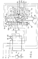
- phase separator 90 in the plant shown in Figure 2 is that the vapour taken from the top of the separator 90 for condensation in the condenser-reboiler 46 contains a substantial amount of oxygen and is not suitable for use at the top of the upper stage 58 of the lower pressure rectifier 34 as liquid nitrogen reflux. Accordingly the inlet 74 is located not at a top region of the upper stage 58 of the lower pressure rectifier 34 (i.e. above the entire liquid-vapour contact means located therein) but rather at an intermediate level such that there are some liquid-vapour contact surfaces located above the level of the inlet 74.
- the condensate from the condenser-reboiler 46 that is sent to the lower pressure rectifier 34 is not sub-cooled upstream of its passage through the pressure reducing valve 72.
- the condenser-reboiler 46 operates at a higher temperature than it would were the vapour to be condensed therein essentially pure nitrogen. Accordingly, a part of the further-enriched liquid withdrawn through the outlet 48 of the separator 90 by-passes the pressure reducing valve 49 and the condenser-reboiler 46 in the plant shown in Figure 2 and downstream of passage through a pressure reducing valve 104 is introduced through an inlet 106 into the upper stage 58 of the lower pressure rectifier 34 at an intermediate level thereof.
- phase separator 90 in the plant shown in Figure 2 is that since no rectification takes place in the separator 90, there is no need to return any of the condensate from the condenser-reboiler 46 to this separator. Instead, a portion of the condensate is urged by pump 110 into the higher pressure rectification column 12 through an inlet 112. As a result, the rate of forming liquid nitrogen in the higher pressure rectification column 12 is enhanced. Moreover, no stream of liquid air is withdrawn from an intermediate level of the rectification column 12 in order to provide feeds for the lower pressure rectifier 34 and the flash separator 90. Accordingly, the pressure reducing valves 53 and 54 and associated conduits are omitted from the plant shown in Figure 2. An additional change is that all the first stream of feed air flows through the condenser-reboiler 16 and is introduced into the higher pressure rectification column through an inlet 114 which takes the place of the inlets 14 and 18 shown in Figure 1.
- the condenser-reboiler is located upstream of the phase separator 90 whereby some of the liquid in the liquid-vapour mixture exiting the pressure reducing valve 40 is boiled upstream of the inlet 44 to the phase separator 90.
- the power consumption of each process is defined as the power required to compress the product streams up to the pressure of the feed air stream and therefore represents the work consumed in the separation process.
- the power consumptions are expressed relatively in Table 2 with that for the process according to EP-A-538 118 being 100.
- the ratio of the air pressure, which (less pressure drop in the main heat exchanger) is the pressure at the bottom of the higher pressure rectifier, to the nitrogen pressure which (less pressure drop) is the pressure at the top of the lower pressure rectifier, is less in the operation of the plants according to Figures 1 and 2 of the accompanying drawings than in operation of the process according to EP-A-0 538 118. Accordingly, for a given operating pressure for the lower pressure column, the higher pressure column 12 of the plants shown in Figures 1 and 2 of the accompanying drawings operates at lower pressure than the corresponding column in a process according to EP-A-0 538 118. This can be a considerable advantage as manufacturing difficulties tend to increase with the pressure at which the column is required to operate. Moreover, the advantages in power consumption are manifest. These advantages outweigh the reduced recovery of oxygen in the process according to the invention.
- the rectifier 34 comprises a single vessel 120 instead of the separate vessels 58 and 60 of the plant shown in Figure 2. Accordingly, the reboiler 22 is located at an intermediate level within the vessel or column 120.
- the plant shown in Figure 4 produces an impure nitrogen product in addition to the relatively pure nitrogen product taken from the outlet 78 of the lower pressure rectifier 34.
- an impure liquid nitrogen stream is withdrawn from the higher pressure rectifier 12 through an outlet 122, is sub-cooled by passage through a part of the heat exchanger 38 is reduced in pressure by passage through a throttling valve 124 and is introduced into the lower pressure rectifier 34 through an inlet 126.
- a gaseous nitrogen product is withdrawn from the lower pressure rectifier 34 through an outlet 128 and flows through the heat exchangers 38 and 6 cocurrently with the purer nitrogen product taken from the lower pressure rectifier 34 through its outlet 78.
- the condenser-reboiler 28 is located within the vessel 90.
- the condenser-reboiler 28 may be of the thermo-siphon kind and be at least partially immersed in liquid within the vessel 90.
- the plant shown in Figure 5 is generally similar to that shown in Figure 4 (and therefore like parts in the two Figures are identified by the same reference numerals) except that the reboiler 16 is located outside the lower pressure rectifier 34.
- the composition of the liquid that is reboiled in the condenser-reboiler 16 is different from that of the impure liquid oxygen product that is reboiled in the condenser-reboiler 94.
- the liquid that is vaporised in the condenser-reboiler 94 is taken directly (via the outlet 98) from the bottom of the liquid-vapour mass exchange means (not shown) in the lower pressure rectifier 34 without passing into the sump 130 of the rectifier 34.
- Some of the liquid leaving the bottom of the liquid-vapour mass exchange means in the lower pressure rectifier 34 is however upheld to pass under gravity into the sump 130 in which it is mixed with liquid relatively richer in nitrogen which is taken from a mass exchange level of the lower pressure rectification column 34 adjacent to but below the condenser-reboiler 22.
- the resulting mixture is withdrawn through an outlet 132 and flows through the boiling passages of the condenser-reboiler 16 and is thereby reboiled.
- the resulting vapour is reintroduced into the lower pressure rectifier 34 at a level below the liquid-vapour mass exchange means (not shown) located therein.
- FIG. 6 of the drawings shows alternative modifications that may be made to the plant illustrated in Figure 4 and again like parts in the two Figures are identified by the same reference numerals.
- the further enrichment the oxygen-enriched liquid is performed in two discrete stages, the downstream one of which corresponds to the reboiler-condenser 28 and vessel 90 of the plant shown in Figure 4, and the upstream one of which has no counterpart in the plant shown in Figure 4.
- oxygen-enriched liquid is withdrawn from the higher pressure rectifier 12 through an outlet 36 and is sub-cooled by passage through the heat exchanger 38.
- the sub-cooled oxygen-enriched liquid is flashed through a pressure reducing valve 140 into an auxiliary rectification column 142 below the level of all liquid-vapour contact means (not shown) therein.
- the oxygen-enriched liquid is separated in the auxiliary rectification column 142 into a further-enriched liquid and nitrogen vapour.
- the nitrogen vapour that is so separated is not pure.
- Reflux for the auxiliary rectification column 142 is formed by withdrawing a stream of nitrogen vapour from the top of the column 142 and condensing it in a condenser-reboiler 144 located at an intermediate mass exchange level of the lower pressure rectifier 34 above that at which the condenser-reboiler 22 is situated.
- Condensation of the impure nitrogen vapour in the condenser-reboiler 144 is thus effected by indirect heat exchange with boiling liquid taken from mass exchange in the lower pressure rectifier 34.
- a part of the resulting condensate is returned to the top of the auxiliary rectification column 142 as reflux while another part of it is passed through a pressure reducing valve 146 and is introduced into the lower pressure rectifier 34 through an inlet 148.
- Reboil for the auxiliary rectification column 142 is provided by yet another condenser-reboiler 150 located in a sump of the column 142.
- the condenser-reboiler 150 is heated by nitrogen vapour taken from the top of the higher pressure rectifier 12 through the outlet 26.
- This nitrogen is condensed in the condenser-reboiler 150 and the resulting condensate is returned to the higher pressure rectifier 12 via the inlet 32 as liquid nitrogen reflux. Further enriched liquid is withdrawn from the bottom of the auxiliary rectification column 142 and is flashed through a pressure reducing valve 40 and is introduced into the condenser-reboiler 28 located within the vessel 90.
- the operation of this condenser-reboiler 28 is substantially as described with reference to Figure 2.
- the higher pressure rectification column 12 has an operating pressure of 10.2 bar
- the auxiliary rectification column 142 an operating pressure of 7.8 bar
- the vessel 90 has an outlet pressure of 6.5 bar.
- the lower pressure rectifier 34 has an operating pressure of about 4.5 bar and the impure liquid oxygen product is vaporised at about 3.2 bar.
- the resulting fluid stream is introduced into a condenser-reboiler 160 and is totally vaporised therein.
- the resulting vapour is withdrawn from the condenser-reboiler 160 through an outlet 162 and is warmed to ambient temperature by passage through the main heat exchanger 6.
- Heating for the condenser-reboiler 160 is provided by nitrogen taken from the top of the auxiliary column 142.
- the nitrogen condenses and the resulting condensate is returned to the top of the auxiliary column 142 and serves as reflux for that column.
- Impure liquid nitrogen is withdrawn from the top of the column 142 through an outlet 164, is sub-cooled in the heat exchanger 38, and is merged with the impure liquid nitrogen withdrawn from the column 122 downstream of a pressure reducing valve 166.
- Impure liquid nitrogen is withdrawn from the top of the column 142 through an outlet 164, is sub-cooled in the heat exchanger 38, and is merged with the impure liquid nitrogen withdrawn from the column 122 downstream of a pressure reducing valve 166.
- the higher pressure rectification column 12 may have an operating pressure of approximately 13 bar, the lower pressure rectifier an operating pressure of about 6 bar, the auxiliary column 142 an operating pressure of 10 bar, the condenser-reboiler 148 an operating pressure of about 8 bar and the condenser-reboiler 160 an operating pressure (in its boiling passages) of approximately 2.6 bar.
- FIG 8 there is shown a modification to the plant illustrated in Figure 4.
- the vessel 90 is replaced by a small rectification column 170 typically having a few trays (not shown) located above the condenser-reboiler 28 which is located in the bottom of the column 170.
- the oxygen-enriched liquid stream is introduced into the column 170 through the inlet 44 at a level above all the liquid-vapour contact trays therein. This liquid descends the column 170 flowing from tray to tray. It comes into contact with vapour boiled in the reboiler-condenser 28. Mass exchange takes place between the rising vapour and the descending liquid with the result that the further enrichment in oxygen of the liquid is enhanced.
- the construction and operation of the plant shown in Figure 8 is wholly analogous to the plant shown in Figure 4.
Description
- This invention relates to a method and apparatus for separating air.
- The most important method commercially of separating air is by rectification. The most frequently used air separation cycles include the steps of compressing a stream of air, purifying the resulting stream of compressed air by removing water vapour and carbon dioxide, and pre-cooling the stream of compressed air by heat exchange with returning product streams to a temperature suitable for its rectification. The rectification is performed in a so-called "double rectification column" comprising a higher pressure and a lower pressure rectification column i.e. one of the two columns operates at higher pressure than the other. Most if not all of the air is introduced into the higher pressure column and is separated into oxygen-enriched liquid air and liquid nitrogen vapour. The nitrogen vapour is condensed. A part of the condensate is used as liquid reflux in the higher pressure column. Oxygen-enriched liquid is withdrawn from the bottom of the higher pressure column, is sub-cooled, and is introduced into an intermediate region of the lower pressure column through a throttling or pressure reduction valve. The oxygen-enriched liquid is separated into substantially pure oxygen and nitrogen products in the lower pressure column. These products are withdrawn in the vapour state from the lower pressure column and form the returning streams against which the incoming air stream is heat exchanged. Liquid reflux for the lower pressure column is provided by taking the remainder of the condensate from the higher pressure column, sub-cooling it, and passing it into the top of the lower pressure column through a throttling or pressure reduction valve.
- Conventionally, the lower pressure column is operated at pressures in the range of 1 to 1.5 atmospheres absolute. Liquid oxygen at the bottom of the lower pressure column is used to meet the condensation duty at the top of the higher pressure column. Accordingly, nitrogen vapour from the top of higher pressure column is heat exchanged with liquid oxygen in the bottom of the lower pressure column. Sufficient liquid oxygen is able to be evaporated thereby to meet the requirements of the lower pressure column for reboil and to enable a good yield of gaseous oxygen product to be achieved. The pressure at the top of the higher pressure column and hence the pressure to which the incoming air is compressed are arranged to be such that the temperature of the condensing nitrogen is a degree or two Kelvin higher than that of the boiling oxygen in the lower pressure column. In consequence of these relationships, it is not generally possible to operate the higher pressure column below a pressure of about 5 bar.
- Improvements to the air separation process enabling the higher pressure column to be operated at a pressure below 5 bar have been proposed when the oxygen product is not of high purity, containing, say, from 3 to 20% by volume of impurities. US-A-4 410 343 (Ziemer) discloses that when such lower purity oxygen is required, rather than having the above-described link between the lower and higher pressure columns, air is employed to boil oxygen in the bottom of the lower pressure column in order both to provide reboil for that column and to evaporate the oxygen product. The resulting condensed air is then fed into both the higher pressure and the lower pressure columns. A stream of oxygen-enriched liquid is withdrawn from the higher pressure column, is passed through a throttling valve and a part of it is used to perform the nitrogen condensing duty at the top of the higher pressure column.
- US-A-3 210 951 also discloses a process for producing impure oxygen in which air is employed to boil oxygen in the bottom of the lower pressure column in order both to provide reboil for that column and to evaporate the oxygen product. In this instance, however, oxygen-enriched liquid from an intermediate region of the lower pressure column is used to fulfil the duty of condensing nitrogen vapour produced in the higher pressure column. This process is capable of reducing the operating pressure of the higher pressure column close to 4 bar.
- The methods disclosed in US-A-3 210 951 and US-A-410 343 become less suitable for use if the lower pressure column is to be operated at a pressure in excess of about 1.5 bar.
- EP-A-0 538 118 discloses a method of operating a double column process above the conventional pressure limits without loss of oxygen recovery and with improvements in power consumption. In one example, oxygen-enriched liquid air is taken from the bottom of the higher pressure rectification column and is introduced into a further column at a level above all the liquid-vapour mass exchange surfaces therein. The further column operates at pressures intermediate those in the higher pressure column and those in the lower pressure column. The further column provides a liquid feed and a vapour feed to intermediate levels of the lower pressure rectification column. (The precharacterising parts of
claim 1 and 14 are based on EP-A-0 538 118.) - It is an aim of the present invention to provide air separation methods and apparatuses which are operable more efficiently at elevated lower pressure rectifier pressures than are the above described prior art processes.
- According to the present invention there is provided a method of separating air, comprising the steps of:
- a) separating pre-cooled and purified air in a higher pressure rectifier into oxygen-enriched liquid and nitrogen vapour;
- b) separating a stream of the oxygen-enriched liquid at a pressure between the pressure at the top of the higher pressure rectifier and that at the bottom of a lower pressure rectifier so as to form a liquid further enriched in oxygen and an intermediate vapour;
- c) separating a stream of the further-enriched liquid in the lower pressure rectifier into oxygen and nitrogen; and
- d) providing liquid nitrogen reflux for the higher and lower pressure rectifiers, characterised in that a part of the liquid nitrogen reflux is formed by condensing a stream of said nitrogen vapour from the higher pressure rectifier by indirect heat exchange with liquid from an intermediate mass transfer region of the lower pressure rectifier.
-
- The invention also provides apparatus for separating air, comprising:
- a) a higher pressure rectifier for separating pre-cooled and purified air into oxygen-enriched liquid and nitrogen vapour;
- b) a lower pressure rectifier for producing oxygen and nitrogen;
- c) means for separating a stream of the oxygen-enriched liquid at a pressure between the pressure at the top of the higher pressure rectifier and that at the bottom of the lower pressure rectifier so as to form a liquid further enriched in oxygen and an intermediate vapour;
- d) means for introducing a stream of the further-enriched liquid into the lower pressure rectifier for separation into oxygen and nitrogen; and
- e) means for providing liquid nitrogen reflux for the higher and lower pressure rectifiers characterised in that the means for providing liquid nitrogen reflux includes a condenser for indirectly heat exchanging a stream of said nitrogen vapour from the higher pressure rectifier with liquid from an intermediate mass transfer region of the lower pressure rectifier.
-
- The separation of the stream of the said oxygen enriched liquid in step (b) of the method according to the invention is performed either by (i) rectification in a further rectifier (sometimes referred to hereinafter as "intermediate rectification") or by (ii) flashing the stream of oxygen-enriched liquid to form a liquid-vapour mixture at said pressure between the pressure at the top of the higher pressure rectifier and that at the bottom of the lower pressure rectifier; and separating the resulting liquid-vapour mixture into liquid and vapour phases to form the further enriched liquid and the intermediate vapour, these steps sometimes being referred to collectively as "intermediate flash separation". In order to enhance the rate of formation of the intermediate vapour a part of the further enriched liquid is preferably reboiled.
- If step (b) of the method according to the invention is performed by intermediate rectification, the stream of oxygen-enriched liquid is introduced below all liquid-vapour mass exchange means in the further rectifier or the incoming feed to it.
- Reboiling of this liquid is preferably performed by indirect heat exchange with another stream of nitrogen from the higher pressure rectifier, the nitrogen thereby being condensed. The nitrogen condensate provides a further source of reflux which is preferably employed in the higher pressure rectifier. The further rectifier is preferably provided with a reboiler so as partially to reboil liquid at the bottom of the further rectifier. The further rectifier preferably produces, as the intermediate vapour, nitrogen. The nitrogen is preferably condensed to form yet further liquid nitrogen reflux, a part of which is preferably used in the lower pressure rectifier and another part of which is preferably used in the further rectifier.
- If step (b) of the method according to the invention is performed by intermediate flash separation, the partial reboiling may be performed upstream of or in the phase separator. The partial reboiling may be performed by indirect heat exchange with another stream of nitrogen vapour from the higher pressure rectifier, the nitrogen thereby being condensed. The nitrogen condensate provides a further source of reflux which is preferably employed in the higher pressure rectifier. Yet further liquid nitrogen reflux is preferably formed by indirect heat exchange of nitrogen from the higher pressure rectifier with liquid oxygen withdrawn from a bottom region of the lower pressure rectifier, which liquid oxygen preferably enters into the indirect heat exchange at a pressure less than that at the top of the lower pressure rectifier. The liquid oxygen is thereby vaporised and may be taken as product. The yet further liquid nitrogen reflux is typically used as reflux in the higher pressure rectifier.
- If step (b) of the method according to the invention is performed by intermediate flash separation, the said intermediate vapour is preferably condensed and the resulting condensate is preferably returned to the higher pressure rectifier, thereby enhancing the rate of production of liquid nitrogen reflux.
- Irrespective of how step (b) is performed, condensation of the intermediate vapour is preferably performed by indirect heat exchange with a stream of said further-enriched liquid, which stream is reduced in pressure upstream of the heat exchange. The stream of said further-enriched liquid is typically partially vaporised thereby and the resulting fluid is preferably introduced into the lower pressure rectifier. (If desired, a stream of further-enriched liquid may be introduced into the lower pressure rectifier, by-passing the indirect heat exchange with the intermediate vapour.) Alternatively, the intermediate vapour may be condensed by indirect heat exchange with liquid taken from an intermediate mass transfer region of the lower pressure rectifier, the liquid taken from the intermediate mass transfer region of the lower pressure rectifier thereby being at least partially reboiled. It is preferably returned to a mass transfer region of the lower pressure rectifier.
- Typically, reboil for the lower pressure rectifier is provided by indirect heat exchange in a reboiler-condenser with a stream of pre-cooled and purified feed air, the feed air stream thereby being at least partially condensed.
- The higher pressure rectifier and further rectifier preferably each comprise a rectification column. The lower pressure rectifier may also comprise a single rectification column or may comprise two separate columns. The latter arrangement offers the advantage that the said condenser for indirectly heat exchanging a stream of said nitrogen vapour with liquid from an intermediate mass transfer region of the lower pressure rectifier may be located in a bottom region of one column and may therefore be a condenser-reboiler of the conventional thermo-siphon kind.
- The oxygen separated in the lower pressure rectifier is preferably from 85 to 96% pure. The nitrogen separated in the lower pressure rectifier is preferably at least 98% pure.
- Refrigeration for the method according to the invention may be created by expansion with the performance of external work of a stream of either the feed air or a nitrogen stream.
- The method and apparatus according to the invention will now be described by way of example with reference to the accompanying drawings, in which:
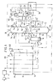
- Figure 1 is a schematic flow diagram of a first air separation plant according to the invention;
- Figure 2 is a schematic flow diagram of a second air separation plant according to the invention;
- Figure 3 is a McCabe-Thiele diagram for operation of the plant shown in Figure 2;
- Figures 4 to 8 are schematic flow diagrams of further air separation plants according to the invention.
-
- In the ensuing description of Figure 1, parameters set out in square brackets are those obtained in a computer simulation of the operation of the plant depicted therein.
- Referring to Figure 1 of the drawings, a feed air stream is compressed in a
compressor 2 and the resulting compressed feed air stream is passed through apurification unit 4 effective to remove water vapour and carbon dioxide therefrom. - The
unit 4 employs beds (not shown) of adsorbent to effect this removal of water vapour and carbon dioxide. The beds are operated out of sequence with one another such that while one or more beds are purifying the feed air stream the remainder are being regenerated, for example by being purged with a stream of hot nitrogen. Such a purification unit and its operation are well known in the art and need not be described further. - The purified feed air stream [temperature, 297K; pressure, 12.3 bar] is divided into first and second air streams. The first air stream [flow rate - 95823 sm3/hr] flows through a
main heat exchanger 6 from itswarm end 8 to itscold end 10 and is thereby cooled from about ambient temperature to its saturation temperature (or other temperature suitable for its separation by rectification) [116.9K]. A first part of the cooled first air stream [flow rate - 51082 sm3/hr] is introduced into a bottom region of a higherpressure rectification column 12 through aninlet 14. A second part of the first cooled air stream [flow rate - 44741 sm3/hr] is at least partially condensed by passage through the condensing passages of a first condenser-reboiler 16. The resulting at least partially condensed air [state - 100% liquid; temperature - 109.3K] is introduced into the higherpressure rectification column 12 through aninlet 18. The higherpressure rectification column 12 contains liquid-vapour contact means (not shown) whereby a descending liquid phase is brought into intimate contact with an ascending vapour phase such that mass transfer between the two phases takes place. - The descending liquid phase becomes progressively richer in oxygen and the ascending vapour phase progressively richer in nitrogen. The liquid-vapour contact means may comprise an arrangement of liquid-vapour contact trays and associated downcomers or may comprise a structured or random packing. A volume (not shown) of liquid typically collects at the bottom of the higher
pressure rectification column 12. - The
inlet 14 is typically located so that the air is introduced into thecolumn 12 below the liquid-vapour contact means or otherwise such that the liquid at the bottom of the higherpressure rectification column 12 is approximately in equilibrium with the incoming air. Accordingly, since oxygen is less volatile than the other main components (nitrogen and argon) of the air, the liquid collecting at the bottom of the higher pressure rectification column 12 (typically in a sump) has an oxygen concentration greater than that of air, i.e. is enriched in oxygen. - A sufficient number of trays or a sufficient height of packing is included in the liquid-vapour contact means (not shown) for the vapour fraction passing out of the top of the liquid-vapour contact means to be essentially pure nitrogen. A first stream of the nitrogen vapour is withdrawn from the top of the higher
pressure rectification column 12 through anoutlet 20 and is condensed in a second reboiler-condenser 22. The condensate is returned to acollector 30 at the top of the higherpressure rectification column 12 through aninlet 24. A second stream of the nitrogen vapour is withdrawn from the top of the higherpressure rectification column 12 through anoutlet 26 and is condensed in a third condenser-reboiler 28. The condensate is returned from the condenser-reboiler 28 to thecollector 30 via aninlet 32. A part of the liquid nitrogen entering thecollector 30 is used as liquid nitrogen reflux in the higherpressure rectification column 12; another part of the condensate is, as will be described below, used as liquid reflux in alower pressure rectifier 34. - A stream of oxygen-enriched liquid (typically containing about 32% by volume of oxygen) [composition (mole fractions) 0.32 O2; 0.01 Ar; 0.67 N2; pressure - 12 bar; temperature - 110.7K; flow rate - 44519 sm3/hr] is withdrawn from the bottom of the higher
pressure rectification column 12 through anoutlet 36 and is sub-cooled in aheat exchanger 38. The sub-cooled oxygen-enriched liquid stream is flashed through a firstpressure reducing valve 40 and a resulting mixture of a flash gas and a residual liquid further enriched in oxygen is formed. The mixture of further-enriched liquid and oxygen-depleted gas is introduced into a bottom region of an intermediate rectification column 42 through aninlet 44. Reboil for the intermediate rectification column 42 is provided by the second condenser-reboiler 28 which is situated at the bottom of the column 42. The condenser-reboiler 28 provides an upward flow of vapour from the bottom of the column 42. Another condenser-reboiler 46 condenses vapour taken from the top of the intermediate rectification column 42. A part of the resulting condensate is returned to the column 42 as reflux. Another part is used as reflux in thelower pressure rectifier 34 as will be described below. There is desirably a sufficient number of distillation trays (not shown) or a sufficient height of packing (not shown) in the intermediate rectification column 42 for the mass exchange between descending liquid and ascending vapour to produce essentially pure nitrogen at the top of the column 42. Thus the condensate formed in the condenser-reboiler 46 is essentially liquid nitrogen. If desired, a gaseous nitrogen product may also be taken from the column 42. - The condenser-
reboiler 28 effects a partial reboil of liquid at the bottom of the intermediate rectification column 42. A stream of residual further-enriched liquid (typically containing about 40% by volume of oxygen) [composition (mole fractions) 02 - 0.40; Ar - 0.02; N2 - 0.58; pressure - 8.1 bar; temperature - 105.4K; flow rate 38472 sm3/hr] is continuously withdrawn from the bottom of the intermediate rectification column 42 through anoutlet 48 and is passed through a secondpressure reducing valve 49 so as to reduce its pressure to approximately the operating pressure of thelower pressure rectifier 34. A first stream of the resultant pressure-reduced further-enriched liquid (typically containing some vapour) flows through the condenser-reboiler 46, thereby providing cooling for the condensation of the nitrogen vapour therein. The stream of further-enriched liquid is itself at least partially vaporised in the condenser-reboiler 28. The resulting oxygen-enriched stream [state - 66% by weight vapour; 34% by weight liquid; pressure - 4.5 bar; temperature - 99.1 K] is introduced into thelower pressure rectifier 34 as a first feed stream at an intermediate level through aninlet 50. As a second feed stream, a stream of liquid air [composition (mole fraction) O2 - 0.21; Ar - 0.01; N2 - 0.78; temperature - 109.2K; pressure - 12.0 bar; flow rate 26999 sm3/hr] is withdrawn from the higherpressure rectification column 12 through anoutlet 52 at the same level as that of theinlet 18. A part [flow rate 20999 sm3/hr] of the second feed stream is passed through a pressure reduction valve 54 so as to reduce its pressure to approximately that of thelower pressure rectifier 34. The resulting pressure-reduced liquid air stream is introduced into therectifier 34 through aninlet 56. In an alternative arrangement, at least partially condensed air may be supplied from the condenser-reboiler 16 to thelower pressure rectifier 34 via a pressure reducing valve (not shown) without first being introduced into the higherpressure rectification column 12. Another part [flow rate 6000 sm3/hr] of the stream of liquid air withdrawn from the higherpressure rectification column 12 through theoutlet 52 is taken from upstream of the valve 54 and is passed through avalve 53 into the intermediate pressure rectification column and is separated therein. - As shown in Figure 1, the
lower pressure rectifier 34 comprises anupper stage 58 and alower stage 60.Stages conduit 62 from the top of thelower stage 60 to the bottom of theupper stage 58 without passing through any device to reduce or increase its pressure. Similarly, liquid flows from the bottom of theupper stage 58 into the top of thelower stage 60 via aconduit 64 without passing through any device to reduce or increase its pressure. An advantage of the two stage arrangement of thelower pressure rectifier 34 is that the condenser-reboiler 22 can be situated in a bottom region of theupper stage 58 and can therefore be of a conventional thermo-siphon kind. - Separation of the two feed streams in the
lower pressure rectifier 34 results in the formation of oxygen and nitrogen products. Thestages lower pressure rectifier 34 contain liquid-vapour contact means (not shown) whereby a descending liquid phase is brought into intimate contact with an ascending vapour phase such that mass transfer between the two phases takes place. The liquid-vapour contact means (not shown) may be of the same kind as or a different kind from the liquid-vapour contact means used in the higherpressure rectification column 12 or the intermediate pressure rectification column 42. Liquid nitrogen reflux for thelower pressure rectifier 34 is provided from two sources. The first source is anoutlet 66 from thecollector 20 through which a stream of liquid nitrogen [mole fraction N2 - 0.99; pressure - 11.9 bar; temperature - 106.6K; flow rate - 24305 sm3/hr] is withdrawn. The stream of liquid nitrogen is then sub-cooled by passage through theheat exchanger 38. The sub-cooled liquid nitrogen stream [temperature - 94.3K; pressure - 7.8 bar] passes through apressure reducing valve 68 and flows into a top region of theupper stage 58 of thelower pressure rectifier 34 through aninlet 70. A second stream of liquid nitrogen reflux is taken from the condensate of the condenser-reboiler 46. The second stream of reflux is sub-cooled in theheat exchanger 38. The sub-cooled liquid nitrogen [mole fraction, nitrogen 1.0; temperature - 94.3K; pressure - 7.8 bar; flow rate 12047 sm3/hr] flows through apressure reducing valve 72 and is introduced into a top region of theupper stage 58 of thelower pressure rectifier 34 as liquid nitrogen reflux. A downward flow of liquid through thelower pressure rectifier 34 is thereby created. An upward flow of vapour through thelower pressure rectifier 34 is created by operation of the condenser-reboiler 16 to reboil liquid at the bottom of thelower stage 60 of thelower pressure rectifier 34. Flow of vapour through theupper stage 58 of thelower pressure rectifier 34 is enhanced by operation of the condenser-reboiler 22 to reboil liquid at the bottom of this stage. - An oxygen product, typically from 90 to 95% pure, [composition (mole fraction) 02 - 0.95; Ar - 0.03; N2 - 0.02; temperature 107.3K; pressure - 4.6 bar; flow rate - 21525 sm3/hr] is withdrawn from a bottom region of the
lower stage 60 of thelower pressure rectifier 34 through anoutlet 76. This product oxygen stream flows through theheat exchanger 6 from itscold end 10 to itswarm end 8. It is thus warmed to ambient temperature [temperature - 294K; pressure - 4.4 bar]. A product nitrogen stream [composition (mole fraction) O2 - 0.01; N2 - 0.99; temperature - 92.8K; pressure - 4.5 bar; flow rate - 78415 sm3/hr] is withdrawn throughoutlet 78 from the top of theupper stage 58 of thelower pressure rectifier 34. It flows through theheat exchanger 38 thereby providing the necessary cooling for the sub-cooling of the other streams flowing therethrough. From theheat exchanger 38 the nitrogen flows through theheat exchanger 6 from itscold end 10 to itswarm end 8 and leaves theheat exchanger 6 at approximately ambient temperature [temperature - 294K; pressure - 4.3 bar]. - The refrigeration demands of the plant shown in Figure 1 are met by taking a second stream of purified air [temperature - 297K; pressure 12.3 bar; flow rate - 4177 sm3/hr] from the
purification unit 4 and further compressing it in acompressor 80. The compressed second stream of air [temperature - 297K; pressure - 20.6 bar] is then cooled to a temperature intermediate those of thecold end 10 andwarm end 8 of theheat exchanger 6 by passage therethrough cocurrently with the first stream of air. The second air stream is withdrawn [temperature - 251.6K] from an intermediate region of themain heat exchanger 6 and is expanded with the performance of external work in anexpansion turbine 82. The resulting expanded stream of air [temperature - 175K; pressure - 4.6 bar] is returned to theheat exchanger 6 and is further reduced in temperature by passage therethrough. The expanded second stream of air passes out of thecold end 10 of theheat exchanger 6 and is introduced [temperature - 117.3K] into theupper stage 58 of thelower pressure rectifier 34 as a third feed stream which is separated with the other two feed streams. - Referring now to Figure 2 of the drawings, there is shown that the plant having a similar column arrangement to that shown in Figure 1 save that a simple phase separator 90 (in which no rectification takes place) is substituted for the intermediate rectification column 42. As a consequence, a number of changes are made to the plant shown in Figure 1. These changes are described below with reference to Figure 2. First, additional reflux for the higher
pressure rectification column 12 is provided by withdrawing a further stream of nitrogen vapour through anoutlet 92 at a top region of the higherpressure rectification column 12 and condensing a part the stream in another condenser-reboiler 94. (Another part of the stream of nitrogen withdrawn through theoutlet 92 is passed through theheat exchanger 6 from itscold end 10 to itswarm end 8 and is taken as elevated pressure nitrogen product at ambient temperature). The resulting liquid nitrogen condensate is returned to thecollector 30 in the higher pressure rectification column through aninlet 96. Cooling for the condenser-reboiler 94 is provided by withdrawing a stream of liquid oxygen from the bottom region of thelower stage 6 of thelower pressure rectifier 34 through anoutlet 98 and flashing it through apressure reducing valve 100 into the condenser-reboiler 94. The liquid oxygen is vaporised by heat exchange with the nitrogen from the higherpressure rectification column 12. The oxygen vapour is withdrawn from the condenser-reboiler 94 through anoutlet 102 and flows through themain heat exchanger 6 from itscold end 10 to itswarm end 8 as the oxygen product. Accordingly, no gaseous oxygen product stream is withdrawn directly from thelower stage 60 of thelower pressure column 34. - Another consequence of the use of
phase separator 90 in the plant shown in Figure 2 is that the vapour taken from the top of theseparator 90 for condensation in the condenser-reboiler 46 contains a substantial amount of oxygen and is not suitable for use at the top of theupper stage 58 of thelower pressure rectifier 34 as liquid nitrogen reflux. Accordingly theinlet 74 is located not at a top region of theupper stage 58 of the lower pressure rectifier 34 (i.e. above the entire liquid-vapour contact means located therein) but rather at an intermediate level such that there are some liquid-vapour contact surfaces located above the level of theinlet 74. Moreover, the condensate from the condenser-reboiler 46 that is sent to thelower pressure rectifier 34 is not sub-cooled upstream of its passage through thepressure reducing valve 72. For a given operating pressure of theseparator 90, the condenser-reboiler 46 operates at a higher temperature than it would were the vapour to be condensed therein essentially pure nitrogen. Accordingly, a part of the further-enriched liquid withdrawn through theoutlet 48 of theseparator 90 by-passes thepressure reducing valve 49 and the condenser-reboiler 46 in the plant shown in Figure 2 and downstream of passage through apressure reducing valve 104 is introduced through aninlet 106 into theupper stage 58 of thelower pressure rectifier 34 at an intermediate level thereof. - A further consequence of the use of the
phase separator 90 in the plant shown in Figure 2 is that since no rectification takes place in theseparator 90, there is no need to return any of the condensate from the condenser-reboiler 46 to this separator. Instead, a portion of the condensate is urged bypump 110 into the higherpressure rectification column 12 through aninlet 112. As a result, the rate of forming liquid nitrogen in the higherpressure rectification column 12 is enhanced. Moreover, no stream of liquid air is withdrawn from an intermediate level of therectification column 12 in order to provide feeds for thelower pressure rectifier 34 and theflash separator 90. Accordingly, thepressure reducing valves 53 and 54 and associated conduits are omitted from the plant shown in Figure 2. An additional change is that all the first stream of feed air flows through the condenser-reboiler 16 and is introduced into the higher pressure rectification column through aninlet 114 which takes the place of theinlets - It should also be noted that in the plant shown in Figure 2, the condenser-reboiler is located upstream of the
phase separator 90 whereby some of the liquid in the liquid-vapour mixture exiting thepressure reducing valve 40 is boiled upstream of theinlet 44 to thephase separator 90. - Based on a computer simulation, an example of the operation of the plant shown in Figure 2 is given in Table 1 below. In this example all the nitrogen product is taken from the
upper stage 58 of thelower pressure rectifier 34 and hence none from theoutlet 92 of thehigher pressure rectifier 12.


- Operation of the plant shown in Figure 2 in accordance with the example set out in Table 1 is further illustrated by the McCabe-Thiele diagram (Figure 3) which portrays the operating line for the
lower pressure rectifier 34. A relatively close conformity of the operating line with the equilibrium line is achievable without employing an excessive number of theoretical plates in the lower pressure rectifier. - A comparison has been made of the operation of the plants shown in Figures 1 and 2 with the reported operation of a process according to EP-A-0 538 118 (see Table 1 thereof and the associated description). The results of the comparison are shown in Table 2 below.
EP-A-538 118 Figure 1 Figure 2 Air pressure (bar) 16.0 12.33 10.45 N2 pressure (bar) 5.0 4.27 4.27 O2 pressure (bar) 5.16 4.43 3.07 O2 Recovery % 99.4 97.6 97.8 Relative Power Consumption 100 92.6 86.5 Process Efficiency 48.3 52.2 55.8 - The power consumption of each process is defined as the power required to compress the product streams up to the pressure of the feed air stream and therefore represents the work consumed in the separation process. The power consumptions are expressed relatively in Table 2 with that for the process according to EP-A-538 118 being 100.
- It can be appreciated that the ratio of the air pressure, which (less pressure drop in the main heat exchanger) is the pressure at the bottom of the higher pressure rectifier, to the nitrogen pressure which (less pressure drop) is the pressure at the top of the lower pressure rectifier, is less in the operation of the plants according to Figures 1 and 2 of the accompanying drawings than in operation of the process according to EP-A-0 538 118. Accordingly, for a given operating pressure for the lower pressure column, the
higher pressure column 12 of the plants shown in Figures 1 and 2 of the accompanying drawings operates at lower pressure than the corresponding column in a process according to EP-A-0 538 118. This can be a considerable advantage as manufacturing difficulties tend to increase with the pressure at which the column is required to operate. Moreover, the advantages in power consumption are manifest. These advantages outweigh the reduced recovery of oxygen in the process according to the invention. - Various modifications and variations be made to the plant shown in Figures 1 and 2. One example of a modified form of the plant shown in Figure 2 is illustrated by Figure 4. Like parts occurring in Figures 2 and 4 are indicated by the same reference numerals. Since the construction and operation of the plant shown in Figures 2 and 4 are largely the same as one another, only those features of the plant shown in Figure 4 which do not have an exact counterpart in the plant shown in Figure 2 will be described below.
- In the plant shown in Figure 4, the
rectifier 34 comprises asingle vessel 120 instead of theseparate vessels reboiler 22 is located at an intermediate level within the vessel orcolumn 120. - The plant shown in Figure 4 produces an impure nitrogen product in addition to the relatively pure nitrogen product taken from the
outlet 78 of thelower pressure rectifier 34. In order to produce this impure nitrogen product, an impure liquid nitrogen stream is withdrawn from thehigher pressure rectifier 12 through anoutlet 122, is sub-cooled by passage through a part of theheat exchanger 38 is reduced in pressure by passage through a throttlingvalve 124 and is introduced into thelower pressure rectifier 34 through aninlet 126. A gaseous nitrogen product is withdrawn from thelower pressure rectifier 34 through anoutlet 128 and flows through theheat exchangers lower pressure rectifier 34 through itsoutlet 78. - In the plant shown in Figure 4, the condenser-
reboiler 28 is located within thevessel 90. The condenser-reboiler 28 may be of the thermo-siphon kind and be at least partially immersed in liquid within thevessel 90. - The plant shown in Figure 5 is generally similar to that shown in Figure 4 (and therefore like parts in the two Figures are identified by the same reference numerals) except that the
reboiler 16 is located outside thelower pressure rectifier 34. In addition, in operation of the plant shown in Figure 5, the composition of the liquid that is reboiled in the condenser-reboiler 16 is different from that of the impure liquid oxygen product that is reboiled in the condenser-reboiler 94. To achieve this difference in composition, the liquid that is vaporised in the condenser-reboiler 94 is taken directly (via the outlet 98) from the bottom of the liquid-vapour mass exchange means (not shown) in thelower pressure rectifier 34 without passing into thesump 130 of therectifier 34. Some of the liquid leaving the bottom of the liquid-vapour mass exchange means in thelower pressure rectifier 34 is however upheld to pass under gravity into thesump 130 in which it is mixed with liquid relatively richer in nitrogen which is taken from a mass exchange level of the lowerpressure rectification column 34 adjacent to but below the condenser-reboiler 22. The resulting mixture is withdrawn through anoutlet 132 and flows through the boiling passages of the condenser-reboiler 16 and is thereby reboiled. The resulting vapour is reintroduced into thelower pressure rectifier 34 at a level below the liquid-vapour mass exchange means (not shown) located therein. By enriching in nitrogen the liquid being reboiled in the boiling passages of the condenser-reboiler 16, its boiling point is reduced. Accordingly, a complementary reduction in the temperature at which the air condenses in the condenser-reboiler 16 is made by reducing the pressure at which the air is supplied from thecompressor 2 to the condenser-reboiler 16. As a result, it is possible to reduce the operating pressure of the higher pressure rectification column by about 0.5 bar without making any reduction in the operating pressure of thelower pressure rectifier 34. - The plant shown in Figure 6 of the drawings shows alternative modifications that may be made to the plant illustrated in Figure 4 and again like parts in the two Figures are identified by the same reference numerals. In these modifications, the further enrichment the oxygen-enriched liquid is performed in two discrete stages, the downstream one of which corresponds to the reboiler-
condenser 28 andvessel 90 of the plant shown in Figure 4, and the upstream one of which has no counterpart in the plant shown in Figure 4. Referring to Figure 6, oxygen-enriched liquid is withdrawn from thehigher pressure rectifier 12 through anoutlet 36 and is sub-cooled by passage through theheat exchanger 38. The sub-cooled oxygen-enriched liquid is flashed through apressure reducing valve 140 into anauxiliary rectification column 142 below the level of all liquid-vapour contact means (not shown) therein. The oxygen-enriched liquid is separated in theauxiliary rectification column 142 into a further-enriched liquid and nitrogen vapour. The nitrogen vapour that is so separated is not pure. Reflux for theauxiliary rectification column 142 is formed by withdrawing a stream of nitrogen vapour from the top of thecolumn 142 and condensing it in a condenser-reboiler 144 located at an intermediate mass exchange level of thelower pressure rectifier 34 above that at which the condenser-reboiler 22 is situated. Condensation of the impure nitrogen vapour in the condenser-reboiler 144 is thus effected by indirect heat exchange with boiling liquid taken from mass exchange in thelower pressure rectifier 34. A part of the resulting condensate is returned to the top of theauxiliary rectification column 142 as reflux while another part of it is passed through a pressure reducing valve 146 and is introduced into thelower pressure rectifier 34 through aninlet 148. Reboil for theauxiliary rectification column 142 is provided by yet another condenser-reboiler 150 located in a sump of thecolumn 142. The condenser-reboiler 150 is heated by nitrogen vapour taken from the top of thehigher pressure rectifier 12 through theoutlet 26. This nitrogen is condensed in the condenser-reboiler 150 and the resulting condensate is returned to thehigher pressure rectifier 12 via theinlet 32 as liquid nitrogen reflux. Further enriched liquid is withdrawn from the bottom of theauxiliary rectification column 142 and is flashed through apressure reducing valve 40 and is introduced into the condenser-reboiler 28 located within thevessel 90. The operation of this condenser-reboiler 28 is substantially as described with reference to Figure 2. - In one example of the operation of the plant shown in Figure 6 of the drawings, the higher
pressure rectification column 12 has an operating pressure of 10.2 bar, theauxiliary rectification column 142 an operating pressure of 7.8 bar and thevessel 90 has an outlet pressure of 6.5 bar. Thelower pressure rectifier 34 has an operating pressure of about 4.5 bar and the impure liquid oxygen product is vaporised at about 3.2 bar. - In Figure 7 of the accompanying drawings there is shown a plant which can be viewed as a modification to that shown in Figure 6 and like parts in the two Figures are identified by the same reference numerals. In this modification, the vaporisation of the impure liquid oxygen product is employed to condense nitrogen vapour taken from the top of
auxiliary rectification column 142. Thus a single, condenser-reboiler used in the plant shown in Figure 7 to take the place of the condenser-reboilers 94 and 144 of the plant shown in Figure 6. Referring to Figure 7, impure liquid oxygen product is withdrawn from the bottom of thelower pressure rectifier 34 through theoutlet 98 and is reduced in pressure by passage through the throttlingvalve 100. The resulting fluid stream is introduced into a condenser-reboiler 160 and is totally vaporised therein. The resulting vapour is withdrawn from the condenser-reboiler 160 through an outlet 162 and is warmed to ambient temperature by passage through themain heat exchanger 6. Heating for the condenser-reboiler 160 is provided by nitrogen taken from the top of theauxiliary column 142. The nitrogen condenses and the resulting condensate is returned to the top of theauxiliary column 142 and serves as reflux for that column. Impure liquid nitrogen is withdrawn from the top of thecolumn 142 through anoutlet 164, is sub-cooled in theheat exchanger 38, and is merged with the impure liquid nitrogen withdrawn from thecolumn 122 downstream of apressure reducing valve 166. In other respects and construction of operation of the plant shown in Figure 7 is wholly analogous to Figure 6. - In a typical example of the operation of the plant shown in Figure 7, the higher
pressure rectification column 12 may have an operating pressure of approximately 13 bar, the lower pressure rectifier an operating pressure of about 6 bar, theauxiliary column 142 an operating pressure of 10 bar, the condenser-reboiler 148 an operating pressure of about 8 bar and the condenser-reboiler 160 an operating pressure (in its boiling passages) of approximately 2.6 bar. - In Figure 8 there is shown a modification to the plant illustrated in Figure 4. In this modification, the
vessel 90 is replaced by asmall rectification column 170 typically having a few trays (not shown) located above the condenser-reboiler 28 which is located in the bottom of thecolumn 170. The oxygen-enriched liquid stream is introduced into thecolumn 170 through theinlet 44 at a level above all the liquid-vapour contact trays therein. This liquid descends thecolumn 170 flowing from tray to tray. It comes into contact with vapour boiled in the reboiler-condenser 28. Mass exchange takes place between the rising vapour and the descending liquid with the result that the further enrichment in oxygen of the liquid is enhanced. In other respects, the construction and operation of the plant shown in Figure 8 is wholly analogous to the plant shown in Figure 4.
Claims (18)
- A method of separating air, comprising the steps of:characterised in that a part of the liquid nitrogen reflux is formed by condensing a stream of said nitrogen vapour from the higher pressure rectifier by indirect heat exchange with liquid from an intermediate mass transfer region of the lower pressure rectifier.a) separating pre-cooled and purified air in a higher pressure rectifier into oxygen-enriched liquid and nitrogen vapour;b) separating a stream of the oxygen-enriched liquid at a pressure between the pressure at the top of the higher pressure rectifier and that at the bottom of a lower pressure rectifier so as to form a liquid further enriched in oxygen and an intermediate vapour;c) separating a stream of the further-enriched liquid in the lower pressure rectifier into oxygen and nitrogen; andd) providing liquid nitrogen reflux for the higher and lower pressure rectifiers;
- A method as claimed in claim 1, in which the intermediate vapour is condensed by indirect heat exchange with a stream of said further-enriched liquid which has been reduced in pressure upstream of the heat exchange; and the stream of further-enriched liquid is partially vaporised by the heat exchange with the intermediate vapour and the partially vaporised further-enriched liquid is introduced into the lower pressure rectifier.
- A method as claimed in claim 1, in which the intermediate vapour is condensed by indirect heat exchange with liquid taken from an intermediate mass transfer region of the lower pressure rectifier.
- A method as claimed in any one of claims 1 to 3, in which the separation in the step (b) is performed by rectification in a further rectifier.
- A method as claimed in claim 4, in which the stream of oxygen-enriched liquid is introduced below all vapour-liquid mass exchange means in the further rectifier and the intermediate vapour produced in the further rectifier is nitrogen.
- A method as claimed in claim 5, in which a part of the intermediate vapour is condensed and used as reflux in the further rectifier, and another part of the condensed intermediate vapour is used as reflux in the lower pressure rectifier.
- A method as claimed in any one of claims 4 to 6, in which a portion of liquid in the bottom of the further rectifier or a portion of the feed to the further rectifier is reboiled.
- A method as claimed in any one of claims 1 to 4, in which the said step (b) is performed by flashing the stream of oxygen-enriched liquid to form a liquid-vapour mixture at said pressure between the pressure at the top of the higher pressure rectifier and that at the bottom of the lower pressure rectifier, and separating the resulting liquid-vapour mixture into liquid and vapour phases so as to form the further-enriched liquid and the intermediate vapour, and a part of the further-enriched liquid is reboiled so as to enhance the rate of formation of the intermediate vapour.
- A method as claimed in claim 8, in which the intermediate vapour is condensed and the resulting condensate is returned to the higher pressure rectifier.
- A method as claimed in claim 8 or claim 9, in which a part of the further-enriched liquid is reboiled so as to enhance the rate of formation of the intermediate vapour.
- A method as claimed in claim 7 or claim 10, in which the reboiling is performed by indirect heat exchange with a stream of nitrogen vapour from the higher pressure rectifier, the stream of nitrogen vapour thereby being condensed.
- A method as claimed in claim 11, in which the condensed nitrogen vapour formed in the reboiling of the further-enriched liquid is employed as reflux in the higher pressure rectification column.
- A method as claimed in any one of the preceding claims, in which reboil for the lower pressure rectifier is provided by indirect heat exchange with a stream of pre-cooled and purified feed air, whereby the feed air stream is at least partially condensed.
- Apparatus for separating air, comprising:a) a higher pressure rectifier (12) for separating pre-cooled and purified air into oxygen-enriched liquid and nitrogen vapour;b) a lower pressure rectifier (34) for producing oxygen and nitrogen;c) means (42, 40, 28, 90; 142, 40, 28, 90; 170) for separating a stream of the oxygen-enriched liquid at a pressure between the pressure at the top of the higher pressure rectifier (12) and that at the bottom of the lower pressure rectifier (34) so as to form a liquid further enriched in oxygen and an intermediate vapour;d) means for introducing a stream of the further-enriched liquid into the lower pressure rectifier (34) for separation into oxygen and nitrogen; ande) means for providing liquid nitrogen reflux for the higher and lower pressure rectifiers characterised in that the means for providing liquid nitrogen reflux includes a condenser (22) for indirectly heat exchanging a stream of said nitrogen vapour from the higher pressure rectifier (12) with liquid from an intermediate mass transfer region of the lower pressure rectifier (34).
- Apparatus as claimed in claim 14, in which said separating means comprises a further rectifier (42; 142; 170);
- Apparatus as claimed in claimed in claim 14, in which said separating means comprises a pressure reduction valve (40) and a phase separator (90) on the downstream side of the pressure reduction valve (40).
- Apparatus as claimed in claim 15, in which the further rectifier (42; 142; 170) has a condenser (46; 144; 160) and a reboiler (28; 150) associated therewith.
- Apparatus as claimed in claim 16, additionally including a reboiler (28) upstream of or in the phase separator (90).
Applications Claiming Priority (4)
| Application Number | Priority Date | Filing Date | Title |
|---|---|---|---|
| GB9313839 | 1993-07-05 | ||
| GB939313839A GB9313839D0 (en) | 1993-07-05 | 1993-07-05 | Air separation |
| GB9405071 | 1994-03-15 | ||
| GB9405071A GB9405071D0 (en) | 1993-07-05 | 1994-03-16 | Air separation |
Publications (3)
| Publication Number | Publication Date |
|---|---|
| EP0633438A1 EP0633438A1 (en) | 1995-01-11 |
| EP0633438B1 true EP0633438B1 (en) | 1999-03-24 |
| EP0633438B2 EP0633438B2 (en) | 2002-04-17 |
Family
ID=26303180
Family Applications (1)
| Application Number | Title | Priority Date | Filing Date |
|---|---|---|---|
| EP94302953A Expired - Lifetime EP0633438B2 (en) | 1993-07-05 | 1994-04-25 | Air separation |
Country Status (12)
| Country | Link |
|---|---|
| US (1) | US5438835A (en) |
| EP (1) | EP0633438B2 (en) |
| JP (1) | JPH0719727A (en) |
| KR (1) | KR100291684B1 (en) |
| CN (1) | CN1097247A (en) |
| AU (1) | AU682848B2 (en) |
| DE (1) | DE69417299T3 (en) |
| ES (1) | ES2130355T5 (en) |
| GB (1) | GB9405071D0 (en) |
| NZ (1) | NZ260393A (en) |
| PL (1) | PL175600B1 (en) |
| TW (1) | TW314475B (en) |
Families Citing this family (34)
| Publication number | Priority date | Publication date | Assignee | Title |
|---|---|---|---|---|
| DE69419675T2 (en) * | 1993-04-30 | 2000-04-06 | Boc Group Plc | Air separation |
| US5463871A (en) * | 1994-10-04 | 1995-11-07 | Praxair Technology, Inc. | Side column cryogenic rectification system for producing lower purity oxygen |
| GB9500120D0 (en) * | 1995-01-05 | 1995-03-01 | Boc Group Plc | Air separation |
| US5669237A (en) * | 1995-03-10 | 1997-09-23 | Linde Aktiengesellschaft | Method and apparatus for the low-temperature fractionation of air |
| GB9513766D0 (en) * | 1995-07-06 | 1995-09-06 | Boc Group Plc | Air separation |
| GB9521782D0 (en) * | 1995-10-24 | 1996-01-03 | Boc Group Plc | Air separation |
| US5628207A (en) * | 1996-04-05 | 1997-05-13 | Praxair Technology, Inc. | Cryogenic Rectification system for producing lower purity gaseous oxygen and high purity oxygen |
| US5669236A (en) * | 1996-08-05 | 1997-09-23 | Praxair Technology, Inc. | Cryogenic rectification system for producing low purity oxygen and high purity oxygen |
| GB9618577D0 (en) * | 1996-09-05 | 1996-10-16 | Boc Group Plc | Air separation |
| GB9618576D0 (en) * | 1996-09-05 | 1996-10-16 | Boc Group Plc | Air separation |
| GB9619718D0 (en) * | 1996-09-20 | 1996-11-06 | Boc Group Plc | Air separation |
| GB9619717D0 (en) * | 1996-09-20 | 1996-11-06 | Boc Group Plc | Air separation |
| US5675977A (en) * | 1996-11-07 | 1997-10-14 | Praxair Technology, Inc. | Cryogenic rectification system with kettle liquid column |
| US6009723A (en) * | 1998-01-22 | 2000-01-04 | Air Products And Chemicals, Inc. | Elevated pressure air separation process with use of waste expansion for compression of a process stream |
| FR2778234B1 (en) * | 1998-04-30 | 2000-06-02 | Air Liquide | AIR DISTILLATION SYSTEM AND CORRESPONDING COLD BOX |
| FR2787559A1 (en) * | 1998-12-22 | 2000-06-23 | Air Liquide | Air separation using cryogenic distillation has double column receiving compressed, cooled, and expanded air to produce oxygen rich and nitrogen rich fractions |
| US6053008A (en) * | 1998-12-30 | 2000-04-25 | Praxair Technology, Inc. | Method for carrying out subambient temperature, especially cryogenic, separation using refrigeration from a multicomponent refrigerant fluid |
| US6112550A (en) * | 1998-12-30 | 2000-09-05 | Praxair Technology, Inc. | Cryogenic rectification system and hybrid refrigeration generation |
| US6116052A (en) * | 1999-04-09 | 2000-09-12 | Air Liquide Process And Construction | Cryogenic air separation process and installation |
| US6196024B1 (en) | 1999-05-25 | 2001-03-06 | L'air Liquide, Societe Anonyme Pour L'etude Et L'exploitation Des Procedes Georges Claude | Cryogenic distillation system for air separation |
| US6347534B1 (en) | 1999-05-25 | 2002-02-19 | Air Liquide Process And Construction | Cryogenic distillation system for air separation |
| US6202441B1 (en) | 1999-05-25 | 2001-03-20 | Air Liquide Process And Construction, Inc. | Cryogenic distillation system for air separation |
| US6276170B1 (en) | 1999-05-25 | 2001-08-21 | Air Liquide Process And Construction | Cryogenic distillation system for air separation |
| GB0002086D0 (en) * | 2000-01-28 | 2000-03-22 | Boc Group Plc | Air separation |
| GB0002084D0 (en) * | 2000-01-28 | 2000-03-22 | Boc Group Plc | Air separation method |
| US20040020239A1 (en) * | 2002-03-08 | 2004-02-05 | Laforce Craig Steven | Method of producing an oxygen-enriched air stream |
| CA2482454C (en) * | 2002-04-11 | 2011-12-20 | Richard A. Haase | Water combustion technology-methods, processes, systems and apparatus for the combustion of hydrogen and oxygen |
| US8268269B2 (en) | 2006-01-24 | 2012-09-18 | Clearvalue Technologies, Inc. | Manufacture of water chemistries |
| FR2930328A1 (en) * | 2008-04-22 | 2009-10-23 | Air Liquide | Air separating method for oxycombustion application in boiler, involves sending oxygen and nitrogen enriched liquids to low pressure column, removing oxygen enriched gas in condenser, and drawing nitrogen enriched gas from column |
| WO2009130430A2 (en) * | 2008-04-22 | 2009-10-29 | L'air Liquide Societe Anonyme Pour L'etude Et L'exploitation Des Procedes Georges Claude | Method and apparatus for air separation by cryogenic distillation |
| FR2968749A1 (en) * | 2010-12-13 | 2012-06-15 | Air Liquide | Method for air separation by cryogenic distillation for integrated gasification combined cycle system, involves compressing vaporized oxygen without having to be heated more than specific degrees Celsius, and heating compressed oxygen |
| CN102530892A (en) * | 2011-07-21 | 2012-07-04 | 上海启元空分技术发展股份有限公司 | Method for producing high purity nitrogen and under-pressure low purity oxygen |
| JP5685168B2 (en) * | 2011-09-13 | 2015-03-18 | 大陽日酸株式会社 | Low purity oxygen production method and low purity oxygen production apparatus |
| CN112452095B (en) * | 2020-11-10 | 2022-11-08 | 中国石油化工股份有限公司 | Improved tail gas rectification method |
Citations (1)
| Publication number | Priority date | Publication date | Assignee | Title |
|---|---|---|---|---|
| WO1985004000A1 (en) * | 1984-02-27 | 1985-09-12 | Erickson Donald C | High pressure oxygen pumped lox rectifier |
Family Cites Families (14)
| Publication number | Priority date | Publication date | Assignee | Title |
|---|---|---|---|---|
| US3113854A (en) † | 1960-08-25 | 1963-12-10 | Air Prod & Chem | Method and apparatus for separating gaseous mixtures |
| US3210951A (en) † | 1960-08-25 | 1965-10-12 | Air Prod & Chem | Method for low temperature separation of gaseous mixtures |
| GB2057660B (en) * | 1979-05-17 | 1983-03-16 | Union Carbide Corp | Process and apparatus for producing low purity oxygen |
| US4702757A (en) † | 1986-08-20 | 1987-10-27 | Air Products And Chemicals, Inc. | Dual air pressure cycle to produce low purity oxygen |
| US4769055A (en) † | 1987-02-03 | 1988-09-06 | Erickson Donald C | Companded total condensation reboil cryogenic air separation |
| US4895583A (en) † | 1989-01-12 | 1990-01-23 | The Boc Group, Inc. | Apparatus and method for separating air |
| US4936099A (en) † | 1989-05-19 | 1990-06-26 | Air Products And Chemicals, Inc. | Air separation process for the production of oxygen-rich and nitrogen-rich products |
| US5235816A (en) * | 1991-10-10 | 1993-08-17 | Praxair Technology, Inc. | Cryogenic rectification system for producing high purity oxygen |
| US5231837A (en) † | 1991-10-15 | 1993-08-03 | Liquid Air Engineering Corporation | Cryogenic distillation process for the production of oxygen and nitrogen |
| US5257504A (en) † | 1992-02-18 | 1993-11-02 | Air Products And Chemicals, Inc. | Multiple reboiler, double column, elevated pressure air separation cycles and their integration with gas turbines |
| CN1071444C (en) * | 1992-02-21 | 2001-09-19 | 普拉塞尔技术有限公司 | Cryogenic air separation system for producing gaseous oxygen |
| US5263327A (en) * | 1992-03-26 | 1993-11-23 | Praxair Technology, Inc. | High recovery cryogenic rectification system |
| US5245832A (en) * | 1992-04-20 | 1993-09-21 | Praxair Technology, Inc. | Triple column cryogenic rectification system |
| US5233838A (en) * | 1992-06-01 | 1993-08-10 | Praxair Technology, Inc. | Auxiliary column cryogenic rectification system |
-
1994
- 1994-03-16 GB GB9405071A patent/GB9405071D0/en active Pending
- 1994-04-21 US US08/230,667 patent/US5438835A/en not_active Expired - Fee Related
- 1994-04-25 DE DE69417299T patent/DE69417299T3/en not_active Expired - Fee Related
- 1994-04-25 ES ES94302953T patent/ES2130355T5/en not_active Expired - Lifetime
- 1994-04-25 EP EP94302953A patent/EP0633438B2/en not_active Expired - Lifetime
- 1994-04-26 NZ NZ260393A patent/NZ260393A/en unknown
- 1994-04-27 AU AU60735/94A patent/AU682848B2/en not_active Ceased
- 1994-04-28 JP JP6091380A patent/JPH0719727A/en active Pending
- 1994-04-29 CN CN94104648A patent/CN1097247A/en active Pending
- 1994-04-29 PL PL94303271A patent/PL175600B1/en unknown
- 1994-04-30 KR KR1019940009470A patent/KR100291684B1/en not_active IP Right Cessation
- 1994-05-05 TW TW083104090A patent/TW314475B/zh active
Patent Citations (1)
| Publication number | Priority date | Publication date | Assignee | Title |
|---|---|---|---|---|
| WO1985004000A1 (en) * | 1984-02-27 | 1985-09-12 | Erickson Donald C | High pressure oxygen pumped lox rectifier |
Also Published As
| Publication number | Publication date |
|---|---|
| KR100291684B1 (en) | 2001-09-17 |
| US5438835A (en) | 1995-08-08 |
| GB9405071D0 (en) | 1994-04-27 |
| JPH0719727A (en) | 1995-01-20 |
| ES2130355T5 (en) | 2002-12-01 |
| TW314475B (en) | 1997-09-01 |
| DE69417299D1 (en) | 1999-04-29 |
| PL175600B1 (en) | 1999-01-29 |
| NZ260393A (en) | 1996-07-26 |
| AU6073594A (en) | 1995-01-12 |
| PL303271A1 (en) | 1995-01-09 |
| EP0633438B2 (en) | 2002-04-17 |
| EP0633438A1 (en) | 1995-01-11 |
| KR950003776A (en) | 1995-02-17 |
| AU682848B2 (en) | 1997-10-23 |
| DE69417299T2 (en) | 1999-07-15 |
| DE69417299T3 (en) | 2002-08-22 |
| CN1097247A (en) | 1995-01-11 |
| ES2130355T3 (en) | 1999-07-01 |
Similar Documents
| Publication | Publication Date | Title |
|---|---|---|
| EP0633438B1 (en) | Air separation | |
| EP0636845B1 (en) | Air separation | |
| EP0684438B1 (en) | Air separation | |
| US5551258A (en) | Air separation | |
| EP0577349B1 (en) | Air separation | |
| US5657644A (en) | Air separation | |
| US5572874A (en) | Air separation | |
| US5582031A (en) | Air separation | |
| EP0770841B1 (en) | Air separation | |
| EP0721094B1 (en) | Air separation | |
| US5660059A (en) | Air separation | |
| US4717409A (en) | Liquid vapor contact method and apparatus | |
| US5715706A (en) | Air separation | |
| EP0660058B1 (en) | Air separation | |
| US5928408A (en) | Air separation | |
| EP0831284B1 (en) | Air separation |
Legal Events
| Date | Code | Title | Description |
|---|---|---|---|
| PUAI | Public reference made under article 153(3) epc to a published international application that has entered the european phase |
Free format text: ORIGINAL CODE: 0009012 |
|
| AK | Designated contracting states |
Kind code of ref document: A1 Designated state(s): DE ES FR GB IT NL |
|
| 17P | Request for examination filed |
Effective date: 19950123 |
|
| 17Q | First examination report despatched |
Effective date: 19960311 |
|
| GRAG | Despatch of communication of intention to grant |
Free format text: ORIGINAL CODE: EPIDOS AGRA |
|
| GRAG | Despatch of communication of intention to grant |
Free format text: ORIGINAL CODE: EPIDOS AGRA |
|
| GRAH | Despatch of communication of intention to grant a patent |
Free format text: ORIGINAL CODE: EPIDOS IGRA |
|
| GRAH | Despatch of communication of intention to grant a patent |
Free format text: ORIGINAL CODE: EPIDOS IGRA |
|
| GRAH | Despatch of communication of intention to grant a patent |
Free format text: ORIGINAL CODE: EPIDOS IGRA |
|
| GRAA | (expected) grant |
Free format text: ORIGINAL CODE: 0009210 |
|
| AK | Designated contracting states |
Kind code of ref document: B1 Designated state(s): DE ES FR GB IT NL |
|
| ET | Fr: translation filed | ||
| REF | Corresponds to: |
Ref document number: 69417299 Country of ref document: DE Date of ref document: 19990429 |
|
| ITF | It: translation for a ep patent filed |
Owner name: BARZANO' E ZANARDO MILANO S.P.A. |
|
| REG | Reference to a national code |
Ref country code: ES Ref legal event code: FG2A Ref document number: 2130355 Country of ref document: ES Kind code of ref document: T3 |
|
| PLBI | Opposition filed |
Free format text: ORIGINAL CODE: 0009260 |
|
| PLBQ | Unpublished change to opponent data |
Free format text: ORIGINAL CODE: EPIDOS OPPO |
|
| PLAB | Opposition data, opponent's data or that of the opponent's representative modified |
Free format text: ORIGINAL CODE: 0009299OPPO |
|
| PLBF | Reply of patent proprietor to notice(s) of opposition |
Free format text: ORIGINAL CODE: EPIDOS OBSO |
|
| 26 | Opposition filed |
Opponent name: L AIR LIQIDE, SOCIETE ANONYME POUR L ETUDE ET L EX Effective date: 19991222 |
|
| R26 | Opposition filed (corrected) |
Opponent name: L AIR LIQIDE, SOCIETE ANONYME POUR L ETUDE ET L EX Effective date: 19991222 |
|
| NLR1 | Nl: opposition has been filed with the epo |
Opponent name: L AIR LIQIDE, SOCIETE ANONYME POUR L ETUDE ET L EX |
|
| NLR1 | Nl: opposition has been filed with the epo |
Opponent name: L'AIR LIQIDE, SOCIETE ANONYME POUR L'ETUDE ET L'EX |
|
| PLBF | Reply of patent proprietor to notice(s) of opposition |
Free format text: ORIGINAL CODE: EPIDOS OBSO |
|
| PLBF | Reply of patent proprietor to notice(s) of opposition |
Free format text: ORIGINAL CODE: EPIDOS OBSO |
|
| PLBQ | Unpublished change to opponent data |
Free format text: ORIGINAL CODE: EPIDOS OPPO |
|
| PLAB | Opposition data, opponent's data or that of the opponent's representative modified |
Free format text: ORIGINAL CODE: 0009299OPPO |
|
| R26 | Opposition filed (corrected) |
Opponent name: L AIR LIQIDE, SOCIETE ANONYME POUR L ETUDE ET L EX Effective date: 19991222 |
|
| NLR1 | Nl: opposition has been filed with the epo |
Opponent name: L AIR LIQIDE, SOCIETE ANONYME POUR L ETUDE ET L EX |
|
| PLAW | Interlocutory decision in opposition |
Free format text: ORIGINAL CODE: EPIDOS IDOP |
|
| PLAW | Interlocutory decision in opposition |
Free format text: ORIGINAL CODE: EPIDOS IDOP |
|
| REG | Reference to a national code |
Ref country code: GB Ref legal event code: IF02 |
|
| PUAH | Patent maintained in amended form |
Free format text: ORIGINAL CODE: 0009272 |
|
| STAA | Information on the status of an ep patent application or granted ep patent |
Free format text: STATUS: PATENT MAINTAINED AS AMENDED |
|
| PGFP | Annual fee paid to national office [announced via postgrant information from national office to epo] |
Ref country code: NL Payment date: 20020329 Year of fee payment: 9 |
|
| PGFP | Annual fee paid to national office [announced via postgrant information from national office to epo] |
Ref country code: FR Payment date: 20020401 Year of fee payment: 9 |
|
| 27A | Patent maintained in amended form |
Effective date: 20020417 |
|
| AK | Designated contracting states |
Kind code of ref document: B2 Designated state(s): DE ES FR GB IT NL |
|
| PGFP | Annual fee paid to national office [announced via postgrant information from national office to epo] |
Ref country code: GB Payment date: 20020417 Year of fee payment: 9 |
|
| PGFP | Annual fee paid to national office [announced via postgrant information from national office to epo] |
Ref country code: DE Payment date: 20020418 Year of fee payment: 9 |
|
| PGFP | Annual fee paid to national office [announced via postgrant information from national office to epo] |
Ref country code: ES Payment date: 20020509 Year of fee payment: 9 |
|
| NLR2 | Nl: decision of opposition | ||
| ET3 | Fr: translation filed ** decision concerning opposition | ||
| NLR3 | Nl: receipt of modified translations in the netherlands language after an opposition procedure | ||
| REG | Reference to a national code |
Ref country code: ES Ref legal event code: DC2A Date of ref document: 20020716 Kind code of ref document: T5 |
|
| PG25 | Lapsed in a contracting state [announced via postgrant information from national office to epo] |
Ref country code: GB Free format text: LAPSE BECAUSE OF NON-PAYMENT OF DUE FEES Effective date: 20030425 |
|
| PG25 | Lapsed in a contracting state [announced via postgrant information from national office to epo] |
Ref country code: ES Free format text: LAPSE BECAUSE OF NON-PAYMENT OF DUE FEES Effective date: 20030426 |
|
| PG25 | Lapsed in a contracting state [announced via postgrant information from national office to epo] |
Ref country code: NL Free format text: LAPSE BECAUSE OF NON-PAYMENT OF DUE FEES Effective date: 20031101 Ref country code: DE Free format text: LAPSE BECAUSE OF NON-PAYMENT OF DUE FEES Effective date: 20031101 |
|
| NLV4 | Nl: lapsed or anulled due to non-payment of the annual fee |
Effective date: 20031101 |
|
| GBPC | Gb: european patent ceased through non-payment of renewal fee | ||
| PG25 | Lapsed in a contracting state [announced via postgrant information from national office to epo] |
Ref country code: FR Free format text: LAPSE BECAUSE OF NON-PAYMENT OF DUE FEES Effective date: 20031231 |
|
| REG | Reference to a national code |
Ref country code: FR Ref legal event code: ST |
|
| REG | Reference to a national code |
Ref country code: ES Ref legal event code: FD2A Effective date: 20030426 |
|
| PG25 | Lapsed in a contracting state [announced via postgrant information from national office to epo] |
Ref country code: IT Free format text: LAPSE BECAUSE OF NON-PAYMENT OF DUE FEES Effective date: 20050425 |