EP0202792A1 - Apparatus for cutting the contaminated surface of concrete - Google Patents
Apparatus for cutting the contaminated surface of concrete Download PDFInfo
- Publication number
- EP0202792A1 EP0202792A1 EP86303163A EP86303163A EP0202792A1 EP 0202792 A1 EP0202792 A1 EP 0202792A1 EP 86303163 A EP86303163 A EP 86303163A EP 86303163 A EP86303163 A EP 86303163A EP 0202792 A1 EP0202792 A1 EP 0202792A1
- Authority
- EP
- European Patent Office
- Prior art keywords
- cutting
- concrete
- cutter
- contaminated
- guide rollers
- Prior art date
- Legal status (The legal status is an assumption and is not a legal conclusion. Google has not performed a legal analysis and makes no representation as to the accuracy of the status listed.)
- Withdrawn
Links
Images
Classifications
-
- G—PHYSICS
- G21—NUCLEAR PHYSICS; NUCLEAR ENGINEERING
- G21D—NUCLEAR POWER PLANT
- G21D1/00—Details of nuclear power plant
- G21D1/003—Nuclear facilities decommissioning arrangements
-
- B—PERFORMING OPERATIONS; TRANSPORTING
- B23—MACHINE TOOLS; METAL-WORKING NOT OTHERWISE PROVIDED FOR
- B23D—PLANING; SLOTTING; SHEARING; BROACHING; SAWING; FILING; SCRAPING; LIKE OPERATIONS FOR WORKING METAL BY REMOVING MATERIAL, NOT OTHERWISE PROVIDED FOR
- B23D57/00—Sawing machines or sawing devices not covered by one of the preceding groups B23D45/00 - B23D55/00
- B23D57/0084—Sawing machines or sawing devices not covered by one of the preceding groups B23D45/00 - B23D55/00 specially adapted for sawing under water or at places accessible with difficulty
-
- B—PERFORMING OPERATIONS; TRANSPORTING
- B28—WORKING CEMENT, CLAY, OR STONE
- B28D—WORKING STONE OR STONE-LIKE MATERIALS
- B28D1/00—Working stone or stone-like materials, e.g. brick, concrete or glass, not provided for elsewhere; Machines, devices, tools therefor
- B28D1/02—Working stone or stone-like materials, e.g. brick, concrete or glass, not provided for elsewhere; Machines, devices, tools therefor by sawing
- B28D1/04—Working stone or stone-like materials, e.g. brick, concrete or glass, not provided for elsewhere; Machines, devices, tools therefor by sawing with circular or cylindrical saw-blades or saw-discs
- B28D1/045—Sawing grooves in walls; sawing stones from rocks; sawing machines movable on the stones to be cut
-
- Y—GENERAL TAGGING OF NEW TECHNOLOGICAL DEVELOPMENTS; GENERAL TAGGING OF CROSS-SECTIONAL TECHNOLOGIES SPANNING OVER SEVERAL SECTIONS OF THE IPC; TECHNICAL SUBJECTS COVERED BY FORMER USPC CROSS-REFERENCE ART COLLECTIONS [XRACs] AND DIGESTS
- Y02—TECHNOLOGIES OR APPLICATIONS FOR MITIGATION OR ADAPTATION AGAINST CLIMATE CHANGE
- Y02E—REDUCTION OF GREENHOUSE GAS [GHG] EMISSIONS, RELATED TO ENERGY GENERATION, TRANSMISSION OR DISTRIBUTION
- Y02E30/00—Energy generation of nuclear origin
Definitions
- the present invention relates to an apparatus for cutting a concrete surface which has been contaminated by radioactive substances and more particularly, it relates to a cutting apparatus used to cut and remove only the contaminated concrete surface layer at the time of repairing and dismantling nuclear facilities.
- the present invention is a link added to the above-mentioned our study and it is intended to improve the cutting apparatus.
- the apparatus has a capacity of cutting the surface of concrete from several millimeters to several centimeters.
- the depth to which the surface of concrete is contaminated ranges from several millimeters to about 2cm, and when the surface of concrete contaminated is uniformly cut off to the maximum depth, the amount of waste produced increases undesirably.
- moving and directional changing of the cutting blade are achieved same as by the arm mechanism in the power shovel. It is therefore difficult to accurately control the cutting depth, and even those portions of concrete which are not contaminated are cut off, thereby increasing the amount of waste.
- an apparatus for cutting the contaminated surface of concrete is characterized in that a means for controlling the cutting depth of a cutter is located at a cutting section, enabling the concrete surface to be cut only by a depth necessary and enough to remove contaminated portions from the concrete surface although the depth of contaminated concrete changes depending upon various spots on the concrete mass.
- the present invention therefore provides a cutting apparatus capable of freely controlling its cutting depth to cut off only contaminated portions from the surface of concrete and thus reduce the amount of waste produced.
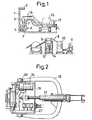
- Fig. 1 schematically shows the whole of an apparatus for cutting the contaminated surface of concrete according to the present invention, which is intended to remove contaminated concrete from concrete wall 1, ceiling 2 and floor 3 in nuclear facilities.
- A represents a cutting section including a cutter 4 and said cutting section serves to cut a concrete surface 5 to remove contaminated portions therefrom. Powdered particles of contaminated concrete which result from cutting the concrete surface by the cutting section A are collected, without being scattered, into a waste collector means 8 through a hood 6 and a suction pipe 7.
- the cutting section A comprising the cutter 4, hood 6, a mechanism for controlling the cutting depth which will be described later, and the like is supported by an arm mechanism 16 which is freely extensible and rotatable and which is mounted on a carrier means 15.
- the arm mechanism 16 and a drive means 17 connected have the same arrangement as that in the power shovel or forklift, thereby enabling the cutter 4 to be moved to any desired angle.
- the waste collector means 8 includes a bag filter unit 9, second filter unit 10, vacuum unit 11, waste collecting/treating container 12 and the like.
- the waste collector means 8 which is provided with rollers 14 is freely movable.
- 15 represents the carrier means intended to support and carry the cutting section A and arm mechanism 16.
- the waste collector means 8 is disclosed in detail on the specification and drawings presented by a Japanese Patent Application (entitled “Mechanism for Collecting Radioactive Dust") which was filed on May 5, 1985.
- the carrier means 15 and the arm mechanism 16 cooperate with each other to contact the cutter 4 with the contaminated surface 5 of concrete and then rotate the cutter 4 to cut the contaminated surface 5 of concrete.
- the contaminated concrete is made powdered particles by this cutting and collected into the container 12 in the waste collector means 8 through the suction pipe 7.
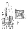
- the cutting section A is freely rotatably attached to the foremost ends of a support arm 18 through a shaft 20 which is fixed to a support frame 19, and it is driven by a hydraulic means 21 to freely change the direction of the cutter 4.
- each of these guide rollers 22 is supported by the support frame 19 through a frame 23 and it is under the control of a motor 24 to move about 10mm in right and left directions in Fig. 3. Due to these forward and backward movements of the guide rollers 22, therefore, the cutter 4 is projected and retreated by about 10mm from its position shown in Fig. 3.
- the cutter 4 is pivoted on a bearing member fixed to the frame 23, and it is driven by a motor 25.
- the frame 23 to which the cutter 4 and guide rollers 22 are attached is movable in relation to the support frame 19 and, as shown in Fig. 3, it is moved in right and left directions in Fig. 3 by means of a hydraulic means 26 whose one end is fixed to the support frame 19.
- the moving amount and direction of the frame 23 in this case are controlled by limit switches .27 shown in Fig. 2.
- the cutter 4 is enclosed by the hood 6 which is provided with a wire brush at the front end portion thereof, and concrete powder cut off from the contaminated surface of concrete is collected, without being scattered, through the suction pipe 7.
- the arm mechanism 16 and hydraulic means 21 are rendered operative, causing the whole face of the cutting section A (or cutter 4) to be contacted face to face with the concrete surface which is to be cut off.
- the hydraulic means 26 is then made operative to strongly press the cutting section A (or cutter 4 and guide rollers 22) against the concrete surface,
- the motor 25 is thereafter made operative to rotate the cutter 4, so that the concrete surface cutting can be achieved to a certain depth, which is controlled by the forward and backward movements of the guide rollers 22 driven by the motor 24 relative to the cutter 4.
- the cutting depth can be controlled easily and the cutting operation can be achieved with high accuracy.
- that portion of concrete which is not to be cut is left not cut, thereby reducing the amount of waste.
- the face of the cutting section ( or cutter ) is left contacted with the concrete face even when repulsive force is generated at the time cutting operation, thereby enabling the cutting operation to stably and efficiently be achieved wiht high accuracy.
Landscapes
- Engineering & Computer Science (AREA)
- Physics & Mathematics (AREA)
- Mechanical Engineering (AREA)
- Plasma & Fusion (AREA)
- General Engineering & Computer Science (AREA)
- High Energy & Nuclear Physics (AREA)
- Mining & Mineral Resources (AREA)
- Working Measures On Existing Buildindgs (AREA)
- Processing Of Stones Or Stones Resemblance Materials (AREA)
- Grinding Of Cylindrical And Plane Surfaces (AREA)
Abstract
Description
- The present invention relates to an apparatus for cutting a concrete surface which has been contaminated by radioactive substances and more particularly, it relates to a cutting apparatus used to cut and remove only the contaminated concrete surface layer at the time of repairing and dismantling nuclear facilities.
- The number of nuclear facilities increases more and more, but it is apparent that permanent use of these facilities is impossible. It is therefore very important to previously study peripheral techniques relating to the repair and dismantlement of nuclear facilities.
- From this viewpoint, we, inventors of the present invention, have studied to prevent workers from being exposed to and contaminated by radioactive substances while to solve the problem of treating a large amount of waste. In the course of this our study, we have filed a Japanese Patent Application 58-153740 (entitled "Method of Removing Contaminated Concrete"), a Japanese Patent Application 58-157406 (entitled "Apparatus for Cutting the Contaminated Surface of Concrete"), and thereafter a Japanese Utility Model Application 59-10292 relating to an improvement of the cutting apparatus.
- Thinking on which these prior arts have based is to remove only those portions which have been contaminated by radioactive substances and treat them as the radioactive waste in aged nuclear facilities, while to repair and dismantle the remaining portions as being clean.
- The present invention is a link added to the above-mentioned our study and it is intended to improve the cutting apparatus. In the case of the cutting apparatus proposed by the above-mentioned Applications, however, nothing is disclosed on controlling the subtle depth of cutting off contaminated portions from the surface of concrete, although the apparatus has a capacity of cutting the surface of concrete from several millimeters to several centimeters. The depth to which the surface of concrete is contaminated ranges from several millimeters to about 2cm, and when the surface of concrete contaminated is uniformly cut off to the maximum depth, the amount of waste produced increases undesirably. In the case of the cutting apparatus proposed above, moving and directional changing of the cutting blade are achieved same as by the arm mechanism in the power shovel. It is therefore difficult to accurately control the cutting depth, and even those portions of concrete which are not contaminated are cut off, thereby increasing the amount of waste.
- According to the present invention, an apparatus for cutting the contaminated surface of concrete is characterized in that a means for controlling the cutting depth of a cutter is located at a cutting section, enabling the concrete surface to be cut only by a depth necessary and enough to remove contaminated portions from the concrete surface although the depth of contaminated concrete changes depending upon various spots on the concrete mass.
- The present invention therefore provides a cutting apparatus capable of freely controlling its cutting depth to cut off only contaminated portions from the surface of concrete and thus reduce the amount of waste produced.
- The invention will be described further, by way of example, with reference to the accompanying drawings, in which:
- Fig. 1 is a diagrammatic side view of apparatus for cutting the contaminated surface of concrete;
- Fig. 2 is a plan view of the main portion of a cutting section of the apparatus;
- Fig. 3 is a side view of the cutting section; and
- Fig. 4 is a front view of the cutting section, showing a cutter and guide rollers.
- Fig. 1 schematically shows the whole of an apparatus for cutting the contaminated surface of concrete according to the present invention, which is intended to remove contaminated concrete from concrete wall 1,
ceiling 2 andfloor 3 in nuclear facilities. In Fig. 1, A represents a cutting section including acutter 4 and said cutting section serves to cut aconcrete surface 5 to remove contaminated portions therefrom. Powdered particles of contaminated concrete which result from cutting the concrete surface by the cutting section A are collected, without being scattered, into a waste collector means 8 through ahood 6 and asuction pipe 7. - The cutting section A comprising the
cutter 4,hood 6, a mechanism for controlling the cutting depth which will be described later, and the like is supported by anarm mechanism 16 which is freely extensible and rotatable and which is mounted on a carrier means 15. Thearm mechanism 16 and a drive means 17 connected have the same arrangement as that in the power shovel or forklift, thereby enabling thecutter 4 to be moved to any desired angle. - The waste collector means 8 includes a
bag filter unit 9,second filter unit 10,vacuum unit 11, waste collecting/treatingcontainer 12 and the like. The waste collector means 8 which is provided withrollers 14 is freely movable. 15 represents the carrier means intended to support and carry the cutting section A andarm mechanism 16. - The waste collector means 8 is disclosed in detail on the specification and drawings presented by a Japanese Patent Application (entitled "Mechanism for Collecting Radioactive Dust") which was filed on May 5, 1985.
- To cut the contaminated surface of concrete according to the system shown in Fig. 1, the carrier means 15 and the
arm mechanism 16 cooperate with each other to contact thecutter 4 with the contaminatedsurface 5 of concrete and then rotate thecutter 4 to cut the contaminatedsurface 5 of concrete. The contaminated concrete is made powdered particles by this cutting and collected into thecontainer 12 in the waste collector means 8 through thesuction pipe 7. - An arrangement of the cutting section A which is an essential matter of the present invention will be described in detail, referring to Figs. 2 through 4.
- The cutting section A is freely rotatably attached to the foremost ends of a
support arm 18 through ashaft 20 which is fixed to asupport frame 19, and it is driven by ahydraulic means 21 to freely change the direction of thecutter 4. - 22 represents guide rollers and the
cutter 4 is provided with fourguide rollers 22 located thereround, as shown in Figs. 3 and 4. Each of theseguide rollers 22 is supported by thesupport frame 19 through aframe 23 and it is under the control of amotor 24 to move about 10mm in right and left directions in Fig. 3. Due to these forward and backward movements of theguide rollers 22, therefore, thecutter 4 is projected and retreated by about 10mm from its position shown in Fig. 3. - The
cutter 4 is pivoted on a bearing member fixed to theframe 23, and it is driven by amotor 25. - The
frame 23 to which thecutter 4 andguide rollers 22 are attached is movable in relation to thesupport frame 19 and, as shown in Fig. 3, it is moved in right and left directions in Fig. 3 by means of ahydraulic means 26 whose one end is fixed to thesupport frame 19. The moving amount and direction of theframe 23 in this case are controlled by limit switches .27 shown in Fig. 2. - The
cutter 4 is enclosed by thehood 6 which is provided with a wire brush at the front end portion thereof, and concrete powder cut off from the contaminated surface of concrete is collected, without being scattered, through thesuction pipe 7. - According to the contaminated concrete cutting apparatus of the present invention whose cutting section A has the above-described arrangement, the
arm mechanism 16 andhydraulic means 21 are rendered operative, causing the whole face of the cutting section A (or cutter 4) to be contacted face to face with the concrete surface which is to be cut off. Thehydraulic means 26 is then made operative to strongly press the cutting section A (orcutter 4 and guide rollers 22) against the concrete surface, And themotor 25 is thereafter made operative to rotate thecutter 4, so that the concrete surface cutting can be achieved to a certain depth, which is controlled by the forward and backward movements of theguide rollers 22 driven by themotor 24 relative to thecutter 4. - An embodiment of the present invention has the above-described arrangement, but it should be understood that the present invention can further include the following embodiments.
- 1) Although the bearing member to which the shaft of each of the
guide rollers 22 is attached has been moved forward and backward by themotor 24 to move theguide rollers 22 forward and backward in the case of the above-described embodiment of the present invention, this mechanism for moving theguide rollers 22 forward and backward may be changed variously. The linear reciprocating movement of a hydraulic means, for example, may be used instead of themotor 24 to move the guide rollers forward and backward. The reciprocating movement of this hydraulic means may be converted to rotating movement. Solenoids can be used in the latter case. - 2) Although the cutting depth has been determined by the relative positional relationship between the
cutter 4 and theguide rollers 22, only thecutter 4 may be moved forward and backward, keeping theguide rollers 22 fixed. To explain it with reference to Fig. 3, theframe 23 for theguide rollers 22 is fixed to thesupport frame 19; themotor 24 and its related members are not used; a frame to which thecutter 4 andhood 6 are fixed is made movable in relation to theframe 23; and it is moved in right and left directions in Fig. 3 by means of thehydraulic means 26. - 3) Although the plane movement of the
cutter 4 relative to the concrete surface has been achieved under the control of thearm mechanism 16 andsupport arm 18, only thecutter 4 orcutter 4 andguide rollers 22 in the cutting section A may be moved in two-dimensional directions at a certain area, without moving thearm mechanism 16 and supportarm 18, to achieve more effective cutting operation. To be more concrete, the frame including thecutter 4, for example, may be moved in two dimensional directions, using guide rails directed in X and Y directions, or this frame may be caused to carry out circumferential movement in relation to the fixed frame. - 4) Although the cutting operation of the
cutter 4 has been performed at the circumferential portion of a rotating drum, cutters of various types which are used at the site in mine and tunnel, for example, may be employed. It is not preferable in this case to use the cutter of that type by which a large amount of concrete powder produced by the cutting operation is scattered, making it likely to leave some of the concrete powder not collected. - 5) A digital display means for displaying the cutting depth may be arranged.
- 6) A sensor for detecting the amount of contamination or cutting depth may be arranged in the cutting section and used as a guide for the cutting depth.
- According to the embodiments of the present invention which have the above-described arrangements, the cutting depth can be controlled easily and the cutting operation can be achieved with high accuracy. In addition, that portion of concrete which is not to be cut is left not cut, thereby reducing the amount of waste. Further, the face of the cutting section ( or cutter ) is left contacted with the concrete face even when repulsive force is generated at the time cutting operation, thereby enabling the cutting operation to stably and efficiently be achieved wiht high accuracy.
Claims (6)
Applications Claiming Priority (2)
| Application Number | Priority Date | Filing Date | Title |
|---|---|---|---|
| JP60104953A JPS61265254A (en) | 1985-05-18 | 1985-05-18 | Grinding machine for contaminated concrete surface |
| JP104953/85 | 1985-05-18 |
Publications (1)
| Publication Number | Publication Date |
|---|---|
| EP0202792A1 true EP0202792A1 (en) | 1986-11-26 |
Family
ID=14394456
Family Applications (1)
| Application Number | Title | Priority Date | Filing Date |
|---|---|---|---|
| EP86303163A Withdrawn EP0202792A1 (en) | 1985-05-18 | 1986-04-25 | Apparatus for cutting the contaminated surface of concrete |
Country Status (2)
| Country | Link |
|---|---|
| EP (1) | EP0202792A1 (en) |
| JP (1) | JPS61265254A (en) |
Cited By (1)
| Publication number | Priority date | Publication date | Assignee | Title |
|---|---|---|---|---|
| KR100962180B1 (en) | 2008-08-26 | 2010-06-10 | 한국원자력연구원 | Concrete surface decontamination unit mounted on the table |
Citations (4)
| Publication number | Priority date | Publication date | Assignee | Title |
|---|---|---|---|---|
| DE2554256A1 (en) * | 1975-12-03 | 1977-06-16 | Steinmueller Gmbh L & C | METHOD OF DISPOSAL OF A NUCLEAR POWER PLANT |
| DE2907738A1 (en) * | 1979-02-28 | 1980-09-04 | Transnuklear Gmbh | Radioactive vessel demolition process - fills with solid material removed again as walls are demolished (BE 26.8.80) |
| US4375212A (en) * | 1981-01-19 | 1983-03-01 | Longyear Company | Concrete sawing machine propulsion control apparatus |
| US4473319A (en) * | 1982-04-27 | 1984-09-25 | Surface Dynamics Inc. | Controlled resurfacing of roads and the like |
Family Cites Families (2)
| Publication number | Priority date | Publication date | Assignee | Title |
|---|---|---|---|---|
| JPS5634814Y2 (en) * | 1977-07-04 | 1981-08-17 | ||
| JPS5845003U (en) * | 1981-09-21 | 1983-03-26 | 川崎重工業株式会社 | Chain saw oil pump drive device |
-
1985
- 1985-05-18 JP JP60104953A patent/JPS61265254A/en active Pending
-
1986
- 1986-04-25 EP EP86303163A patent/EP0202792A1/en not_active Withdrawn
Patent Citations (4)
| Publication number | Priority date | Publication date | Assignee | Title |
|---|---|---|---|---|
| DE2554256A1 (en) * | 1975-12-03 | 1977-06-16 | Steinmueller Gmbh L & C | METHOD OF DISPOSAL OF A NUCLEAR POWER PLANT |
| DE2907738A1 (en) * | 1979-02-28 | 1980-09-04 | Transnuklear Gmbh | Radioactive vessel demolition process - fills with solid material removed again as walls are demolished (BE 26.8.80) |
| US4375212A (en) * | 1981-01-19 | 1983-03-01 | Longyear Company | Concrete sawing machine propulsion control apparatus |
| US4473319A (en) * | 1982-04-27 | 1984-09-25 | Surface Dynamics Inc. | Controlled resurfacing of roads and the like |
Non-Patent Citations (3)
| Title |
|---|
| SOVIET INVENTIONS ILLUSTRATED, sections P,Q, week 83/31, September 14, 1983 DERWENT PUBLICATIONS LTD., London, Q 42 * SU 962 478 (SHILKOV V A) * * |
| SOVIET INVENTIONS ILLUSTRATED, sections P,Q, week B24, July 25, 1979 DERWENT PUBLICATIONS LTD., London, Q 49 * SU 619 117 (COAL INDUSTRY PATENT LTD.) * * |
| SOVIET INVENTIONS ILLUSTRATED, sections P,Q, week E25, August 4, 1982 DERWENT PUBLICATIONS LTD., London, Q 42 * SU 859 555 (GLAVSTROIMEKHANIZAT) * * |
Cited By (1)
| Publication number | Priority date | Publication date | Assignee | Title |
|---|---|---|---|---|
| KR100962180B1 (en) | 2008-08-26 | 2010-06-10 | 한국원자력연구원 | Concrete surface decontamination unit mounted on the table |
Also Published As
| Publication number | Publication date |
|---|---|
| JPS61265254A (en) | 1986-11-25 |
Similar Documents
| Publication | Publication Date | Title |
|---|---|---|
| US4923251A (en) | Apparatus for removing asbestos and like materials from a surface | |
| EP3152767B1 (en) | Device and process for ablation of contaminated material | |
| EP0202792A1 (en) | Apparatus for cutting the contaminated surface of concrete | |
| US4782844A (en) | Texture removal apparatus | |
| JP2001071253A (en) | Method for separating shape-machined thin piece | |
| CN110935925A (en) | A steel drum automatic cutting and dumping device | |
| KR100962180B1 (en) | Concrete surface decontamination unit mounted on the table | |
| US3681863A (en) | Wheel excavators for digging channels and trenches having variably angled slopes | |
| CN208215480U (en) | A kind of plate spacing device | |
| CN211915708U (en) | Automatic cutting and dumping device for steel drum | |
| JP2002081298A (en) | Tunnel inner wall repair machine | |
| CN217571336U (en) | Laser dust cleaning device | |
| JPH1110380A (en) | Laser processing method and laser processing device | |
| GB2333723A (en) | Machines and methods suitable for use in disintegration of rubber tyres | |
| CN116968469A (en) | Sculpture forming device with locate function | |
| JPS60242912A (en) | Deburring method | |
| JPH0639948Y2 (en) | Dust removal device for cutting machine | |
| CN222822368U (en) | A floor cleaning device | |
| JP2000024828A (en) | Cutting device for solid waste storage case | |
| CN222931919U (en) | Dust collecting device for high-speed sawing machine | |
| CN218836251U (en) | Adjustable pipeline cutting device for engineering construction site | |
| JPH11352292A (en) | Self-propelled cutting device | |
| CN223235806U (en) | Mobile gantry numerical control machining center ceiling mechanism | |
| CN212527829U (en) | Edge cutting equipment for carpet production | |
| JP4836785B2 (en) | Device for manipulating an object in a compartment area with a remotely operated fluid pressure arm |
Legal Events
| Date | Code | Title | Description |
|---|---|---|---|
| PUAI | Public reference made under article 153(3) epc to a published international application that has entered the european phase |
Free format text: ORIGINAL CODE: 0009012 |
|
| AK | Designated contracting states |
Kind code of ref document: A1 Designated state(s): DE FR GB |
|
| 17P | Request for examination filed |
Effective date: 19870430 |
|
| 17Q | First examination report despatched |
Effective date: 19881025 |
|
| STAA | Information on the status of an ep patent application or granted ep patent |
Free format text: STATUS: THE APPLICATION IS DEEMED TO BE WITHDRAWN |
|
| 18D | Application deemed to be withdrawn |
Effective date: 19890307 |
|
| RIN1 | Information on inventor provided before grant (corrected) |
Inventor name: FUNAKAWA, NAOYOSHI Inventor name: DEMURA, HAJIME Inventor name: SASAKI, MASAYOSHI |