EP0202754B1 - Body support pad - Google Patents
Body support pad Download PDFInfo
- Publication number
- EP0202754B1 EP0202754B1 EP86302724A EP86302724A EP0202754B1 EP 0202754 B1 EP0202754 B1 EP 0202754B1 EP 86302724 A EP86302724 A EP 86302724A EP 86302724 A EP86302724 A EP 86302724A EP 0202754 B1 EP0202754 B1 EP 0202754B1
- Authority
- EP
- European Patent Office
- Prior art keywords
- body support
- support pad
- recited
- pad
- array
- Prior art date
- Legal status (The legal status is an assumption and is not a legal conclusion. Google has not performed a legal analysis and makes no representation as to the accuracy of the status listed.)
- Expired - Lifetime
Links
- 238000003491 array Methods 0.000 claims abstract description 27
- 238000009423 ventilation Methods 0.000 claims abstract description 22
- 239000006260 foam Substances 0.000 claims description 37
- 210000000689 upper leg Anatomy 0.000 claims description 13
- JOYRKODLDBILNP-UHFFFAOYSA-N Ethyl urethane Chemical compound CCOC(N)=O JOYRKODLDBILNP-UHFFFAOYSA-N 0.000 claims description 8
- 230000003319 supportive effect Effects 0.000 claims description 2
- 208000004210 Pressure Ulcer Diseases 0.000 abstract description 13
- 230000002401 inhibitory effect Effects 0.000 abstract description 4
- 239000000463 material Substances 0.000 description 15
- 230000009286 beneficial effect Effects 0.000 description 6
- 210000001519 tissue Anatomy 0.000 description 6
- LYCAIKOWRPUZTN-UHFFFAOYSA-N Ethylene glycol Chemical compound OCCO LYCAIKOWRPUZTN-UHFFFAOYSA-N 0.000 description 3
- 229920006311 Urethane elastomer Polymers 0.000 description 3
- 230000015572 biosynthetic process Effects 0.000 description 3
- 230000006835 compression Effects 0.000 description 3
- 238000007906 compression Methods 0.000 description 3
- 239000006185 dispersion Substances 0.000 description 3
- 230000001747 exhibiting effect Effects 0.000 description 3
- 239000004744 fabric Substances 0.000 description 3
- 230000003068 static effect Effects 0.000 description 3
- 206010011985 Decubitus ulcer Diseases 0.000 description 2
- 230000008901 benefit Effects 0.000 description 2
- 210000001124 body fluid Anatomy 0.000 description 2
- 239000010839 body fluid Substances 0.000 description 2
- 230000000694 effects Effects 0.000 description 2
- 239000012530 fluid Substances 0.000 description 2
- 239000006261 foam material Substances 0.000 description 2
- 238000002347 injection Methods 0.000 description 2
- 239000007924 injection Substances 0.000 description 2
- QSHDDOUJBYECFT-UHFFFAOYSA-N mercury Chemical compound [Hg] QSHDDOUJBYECFT-UHFFFAOYSA-N 0.000 description 2
- 229910052753 mercury Inorganic materials 0.000 description 2
- 238000000465 moulding Methods 0.000 description 2
- 230000002829 reductive effect Effects 0.000 description 2
- 230000000284 resting effect Effects 0.000 description 2
- 239000002202 Polyethylene glycol Substances 0.000 description 1
- 239000004743 Polypropylene Substances 0.000 description 1
- 230000006978 adaptation Effects 0.000 description 1
- 238000004458 analytical method Methods 0.000 description 1
- 230000033228 biological regulation Effects 0.000 description 1
- 210000001217 buttock Anatomy 0.000 description 1
- 235000019504 cigarettes Nutrition 0.000 description 1
- 230000000295 complement effect Effects 0.000 description 1
- 238000010276 construction Methods 0.000 description 1
- 239000004035 construction material Substances 0.000 description 1
- 238000011109 contamination Methods 0.000 description 1
- 208000037265 diseases, disorders, signs and symptoms Diseases 0.000 description 1
- 208000035475 disorder Diseases 0.000 description 1
- 230000003670 easy-to-clean Effects 0.000 description 1
- 230000002550 fecal effect Effects 0.000 description 1
- 239000003063 flame retardant Substances 0.000 description 1
- 238000005187 foaming Methods 0.000 description 1
- 230000006870 function Effects 0.000 description 1
- 210000001981 hip bone Anatomy 0.000 description 1
- 238000007373 indentation Methods 0.000 description 1
- 230000005764 inhibitory process Effects 0.000 description 1
- 239000003562 lightweight material Substances 0.000 description 1
- 238000004519 manufacturing process Methods 0.000 description 1
- 210000004197 pelvis Anatomy 0.000 description 1
- 239000004033 plastic Substances 0.000 description 1
- 229920003023 plastic Polymers 0.000 description 1
- 229920001223 polyethylene glycol Polymers 0.000 description 1
- 229920000642 polymer Polymers 0.000 description 1
- -1 polypropylene Polymers 0.000 description 1
- 229920001155 polypropylene Polymers 0.000 description 1
- 229920001296 polysiloxane Polymers 0.000 description 1
- 230000001144 postural effect Effects 0.000 description 1
- 239000007787 solid Substances 0.000 description 1
- 208000020431 spinal cord injury Diseases 0.000 description 1
- 230000002485 urinary effect Effects 0.000 description 1
- XLYOFNOQVPJJNP-UHFFFAOYSA-N water Substances O XLYOFNOQVPJJNP-UHFFFAOYSA-N 0.000 description 1
Images


Classifications
-
- A—HUMAN NECESSITIES
- A61—MEDICAL OR VETERINARY SCIENCE; HYGIENE
- A61G—TRANSPORT, PERSONAL CONVEYANCES, OR ACCOMMODATION SPECIALLY ADAPTED FOR PATIENTS OR DISABLED PERSONS; OPERATING TABLES OR CHAIRS; CHAIRS FOR DENTISTRY; FUNERAL DEVICES
- A61G7/00—Beds specially adapted for nursing; Devices for lifting patients or disabled persons
- A61G7/05—Parts, details or accessories of beds
- A61G7/057—Arrangements for preventing bed-sores or for supporting patients with burns, e.g. mattresses specially adapted therefor
- A61G7/05707—Arrangements for preventing bed-sores or for supporting patients with burns, e.g. mattresses specially adapted therefor with integral, body-bearing projections or protuberances
-
- Y—GENERAL TAGGING OF NEW TECHNOLOGICAL DEVELOPMENTS; GENERAL TAGGING OF CROSS-SECTIONAL TECHNOLOGIES SPANNING OVER SEVERAL SECTIONS OF THE IPC; TECHNICAL SUBJECTS COVERED BY FORMER USPC CROSS-REFERENCE ART COLLECTIONS [XRACs] AND DIGESTS
- Y10—TECHNICAL SUBJECTS COVERED BY FORMER USPC
- Y10S—TECHNICAL SUBJECTS COVERED BY FORMER USPC CROSS-REFERENCE ART COLLECTIONS [XRACs] AND DIGESTS
- Y10S5/00—Beds
- Y10S5/944—Beds with upstanding firm massaging projections
-
- Y—GENERAL TAGGING OF NEW TECHNOLOGICAL DEVELOPMENTS; GENERAL TAGGING OF CROSS-SECTIONAL TECHNOLOGIES SPANNING OVER SEVERAL SECTIONS OF THE IPC; TECHNICAL SUBJECTS COVERED BY FORMER USPC CROSS-REFERENCE ART COLLECTIONS [XRACs] AND DIGESTS
- Y10—TECHNICAL SUBJECTS COVERED BY FORMER USPC
- Y10T—TECHNICAL SUBJECTS COVERED BY FORMER US CLASSIFICATION
- Y10T428/00—Stock material or miscellaneous articles
- Y10T428/24—Structurally defined web or sheet [e.g., overall dimension, etc.]
- Y10T428/24174—Structurally defined web or sheet [e.g., overall dimension, etc.] including sheet or component perpendicular to plane of web or sheet
- Y10T428/24182—Inward from edge of web or sheet
-
- Y—GENERAL TAGGING OF NEW TECHNOLOGICAL DEVELOPMENTS; GENERAL TAGGING OF CROSS-SECTIONAL TECHNOLOGIES SPANNING OVER SEVERAL SECTIONS OF THE IPC; TECHNICAL SUBJECTS COVERED BY FORMER USPC CROSS-REFERENCE ART COLLECTIONS [XRACs] AND DIGESTS
- Y10—TECHNICAL SUBJECTS COVERED BY FORMER USPC
- Y10T—TECHNICAL SUBJECTS COVERED BY FORMER US CLASSIFICATION
- Y10T428/00—Stock material or miscellaneous articles
- Y10T428/24—Structurally defined web or sheet [e.g., overall dimension, etc.]
- Y10T428/24628—Nonplanar uniform thickness material
- Y10T428/24661—Forming, or cooperating to form cells
Definitions
- the present invention relates to a body support pad.
- a frequent malady of nonambulatory people such as people confined to beds or wheelchairs is that of the occurrence of decubitus ulcers, frequently referred to as pressure sores or bed sores
- a major cause of the disorder is that conventional bedding and wheelchairs provide little in the way of either body support or reduced seating pressures. As there is little support or reduced pressure, the patient's weight exerted essentially constantly on tissue surrounding the skeletal structure can give rise to the formation of decubitus ulcers.
- Dynamic pads or cushions are those which involve outside power sources to perform their function. Although such systems are convenient for bed confined patients, they are undesirable for wheelchair use due to their lack of mobility. In addition, such dynamic cushions are undesirable as they are relatively expensive.
- Static cushions are generally preferred due to their being less expensive and their ability to provide mobility such as for use in wheelchairs.
- the static cushions can be classed into two categories: (1) bladder type cushions and (2) foam cushions
- Bladder type cushions are basically flexible walled bags such as plastic bags which are filled with a fluid or some form of gel.
- the fluid can be air or water.
- the gel filled bladders are filled with some type of gel material such as ethylene glycol, polyethylene glycol, silicone, and the like.
- Bladder type cushions are shown in U.S. Patent 2,434,641 of Burns; and U.S. Patent Nos. 3,605,145; 3,870,450; and 4,005,236, all of Graebe.
- the foam cushions can be any structure using a piece of foam.
- foam cushions can be solid pieces of foam or some type of foam laminate structure.
- foam type cushions are the "egg crate" cushion and the contoured foam cushions One cushion is disclosed in U.S. Patent 3,231,454 of Williams.
- Foam cushions are generally the least expensive type of cushion.
- the foam cushions are undesirable in that they have a tendency to build up significant amounts of heat.
- a drawback with the build up of heat is that it is believed that heat buildup is a contributing factor to the occurrence of decubitus ulcers.
- the bladder products tend to be more expensive and tend to perform better in terms of pressure distribution. Some of the bladder products are low in weight like their counterparts in the foam cushion areas. Bladder products, like the foam cushions, also tend to cause tremendous heat buildup.
- Another drawback with bladder products is that they tend to elevate the patient to a height greater than foam cushions.
- US-A-3 904 811 discloses a lightweight construction material suitable for use in cushions and mattresses, the material being a foamed polymer sheet formed on its two opposite side into a pattern of rows of alternating like concavities and like convexities, the patterns of said opposite sides having mutually complementary configurations.
- the invention herein is directed to a body support pad which is relatively inexpensive, easy to manufacture, easy to clean, and which provides distribution of the pressure exerted on the pad so as to inhibit the formation of decubitus ulcers. More particularly, the body support pad herein is suited for use on wheelchairs for inhibiting the occurrence of decubitus ulcers on the patient confined to the wheelchair.
- a body support paid comprising:
- a generally planar flexible base member having an upper surface and a lower surface
- a plurality of pillar means extending outwardly from the lower surface and arranged in discrete arrays of pillar means of substantially similar character for substantially evenly contacting any supportive surface upon which the pad is placed while a body is supported on the pad and for providing different resistive forces in each of such discrete arrays of pillar means;
- each array of pod means provides different resistive forces to the body.
- the body support pad herein can be easily moulded of a lightweight material in a single molding step.
- the pad can be molded of an integral material as the pods and pillars are offset from one another.
- the pad herein can be constructed of a durable material which can be resistant to fecal and urinary contamination or other body fluids.
- the pad herein also provides a structure which can be further modified by an attendant or by the user to accommodate particular features of a patient. That is, the various pillars and pods (and particularly the pillars) can be modified by an attendant such as by contouring to fit the needs of a particular patient.
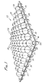
- FIGURE 1 is a perspective view of the body support pad herein;
- FIGURE 2 is a perspective exploded view of a patient support cushion utilizing the body support pad of FIGURE 1;
- FIGURE 3 is a side elevational view of the body support pad of FIGURE 1;
- FIGURE 4 is a top plan view of the body support pad of FIGURE 1;
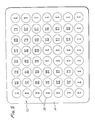
- FIGURE 5 is a diagramatic representation of the pod layout of the body support pad
- FIGURE 6 is a bottom plan view of the body support pad of FIGURE 1;
- FIGURE 7 is a diagramatic view of the pillar placement for the body support pad
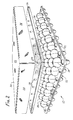
- FIGURE 8 is a cross-sectional view of the body support pad taken along lines 8-8 of FIGURE 4.
- FIGURE 9 is a side elevational view of the body support pad illustrating how the body support pad supports a patient.
- the body support pad that is the subject of the invention herein will be described with regard to the accompanying drawings.
- the body support pad will be described with regard to a body support pad 10 shown in FIGURE 1 designed for use as a seating pad. That is the body support pad 10 shown in FIGURE 1 can be used as a seating pad for use in wheelchairs or on chairs and the like.
- the description herein with regard to the seating pad can be applicable to a pad which can be used for a reclining person such as a mattress pad and the like.
- the body support pad that is the subject of the invention herein will be described with regard to a seating pad as shown in the accompanying drawings.
- a body support pad is constructed of an integrally molded microcellular urethane elastomer having a durometer of about 20 to 40 on the Shore A scale.
- the body support pad is molded from a urethane microcellular urethane elastomer having a density in its molded form of about 0.40.
- Other moldable materials can be used for constructing the body support pad but it has been found that a microcellular urethane elastomer is the preferred material as it provides a pad which is light in weight, provides good distribution of seating pressures, can be easily ventilated, is durable, and generally resistant to body fluids.
- the body support pad 10 includes a generally flexible base member 12 which extends generally in a plane and which has an upper surface 14 and a lower surface 16. Extending upwardly from the upper surface 14 is a plurality of pods 18.
- the pods are generally cylindrical in shape with an upper hemisperical surface.
- the pods 18 also include slits 20 along their sides so that the pods will compress in a substantially uniform manner upon a force being exerted upon them.
- the pods are integrally molded with the base member 12 and are generally hollow structures which are open on the lower surface 16 of the base member as can be more readily seen with regard to FIGURE 6. With regard to FIGURE 6, the pod cavity 25 can be seen which opens into the pods.
- the pillars 22 provide contact with a supporting surface upon which the body support pad 10 is placed while the pods 18 provide contact with a body which rests or is supported by the body support pad 10.
- the pillars 22 are also integrally molded from the material that constitutes the base member.
- the pillars are also hollow structures which are open on the upper surface 14 of the base member through the pillar cavities 24 as can be seen in FIGURES 1 and 4. Also seen in the figures, the pillars and pods are offset from one another so that they can be readily molded and, as will be hereinafter discussed, to provide an acceptable pressure dispersion across the pad assembly.
- FIGURE 1 there are 56 pods arrayed over the upper surface of the base member.
- the number of pods and pillars can be varied, depending upon the use of the pad. It has been found herein that in order to provide the greatest surface area to support a body in a seating position, that 56 pods are preferred and 72 pillars are preferred for a body support pad being about 40 cm (15 and 3/4 inches) wide by about 45 cm (17 and 3/4 inches) deep and 6.7 cm (2 and 5/8 inches) in height.
- the base diameter for the pods being about 4.4 cm (1 and 3/4 inches) and their height about 2.85 cm (1 and 1/8 inch) with four slits 20 extending about 2.5 to 2.8 cm (one to one and one-eighth inches (1 - 1 1/8")) in length.
- the pillars have an opening radius of about 2.85 cm (1 and 1/8 inches) and range in a height from about 1.9 cm (3/4 inch) to 3.18 cm (1 and 1/4 inch).
- the base member has a thickness of about 0.635 cm (1 /4 inch).
- a body support cushion is illustrated in an exploded view.
- the body support pad 10 provides the basic pressure dispersing portion of the overall cushion assembly.
- a foam overlay 26 Layered on the surface provided by the tops of the plurality of pods 18 is a foam overlay 26.
- the foam overlay is a foam pad which is about 1.8 pounds in density with a 30 indentation load deflection (ILD).
- the foam overlay has a high resiliency and can be constructed of any suitable foaming material such as urethane, which is preferred. It is also preferred to have a foam material which is fire retardant in order to comply with most applicable fire regulations and codes. It is preferred to use an open celled foam structure in order to provide adequate ventilation for the body resting upon the cushion.
- a closed cell foam can be used in situations wherein a slow memory for the foam overlay is desired. It has been herein that additional ventilation is preferred and such additional ventilation can be provided by placing ventilation apertures 28 through the foam overlay.
- additional ventilation is preferred and such additional ventilation can be provided by placing ventilation apertures 28 through the foam overlay.
- the ventilation apertures With a sufficient diameter, such as about 0.48 cm (3/16 inch) in diameter, the apertures remain open, even under loading so as to maintain adequate ventilation.
- about 42 ventilation apertures could be provided, each with a diameter of about 0.32 to 0.48 cm (1/8 to 3/16 inch).
- the foam overlay provides an ability to increase the surface area which is in contact with the body and as the surface area is increased over that which could be provided by the individual pods, there is increased comfort to the body.
- the body support cushion also includes a fabric cover 30 which extends over and around both the foam overlay 26 and the body support pad 10.
- the cover 30 provides a means for maintaining the foam overlay on the body support pad.
- the cover provides an upper surface 32 and a sidewall 34 which wraps and extends around the foam overlay and body support pad. It has been found that the cover should be selected from a material which provides wickability, the ability to transport moisture away from the body supported by the pad. It is also desirable to provide a cover which will prevent or at least reduce what is commonly referred to as the hammocking effect.
- the hammocking effect is created by nonstretchable fabrics when a force or load is exerted upon them. Hammocking causes undue forces to be exerted upon a body.
- a preferred material has been found to be a 100% polypropylene which is readily wickable and which is a knitted fabric having a two-way stretch to reduce hammocking. It is also preferred to use an open knit to make the cover as an open knit increases breathability through the material of the cover and, therefore, increases air flow through the cushion assembly. The increased air flow or ventilation of the cushion assembly greatly aids in reducing or inhibiting the occurrence of decubitus ulcers. It is also desirable to provide a cover which will prevent or retard fires should the cover come into contact with a flame or embers such as can occur with fallen cigarettes.
- FIGURE 3 a side elevational view of the body support pad is illustrated.
- the pods 18 are offset from the pillars 22. It has been found herein that by offsetting the pods from the pillars, a beneficial pressure distribution can be created.
- the side elevational view of FIGURE 3 also shows the slits 20 on the pods 18.
- the slits 20 are placed about 90° apart on each pod, thus providing four slits for each pod.
- the slits provide a uniform deflection of each pod upon a force being exerted thereupon.
- the slits also provide an ability for the surface of the pod to maintain a relatively large surface area upon collapse which remains in contact with the body exerting the force and causing the collapse of each pod.
- FIGURE 3 also shows the ability of the pad herein to be ventilated by the appropriate ventilating apertures provided on the pad.
- the pods can include a pod ventilation aperture 38 at or along their upper curved surfaces and the pillars can be provided with a corresponding pillar ventilating aperture 40 on their curved surfaces.
- ventilation apertures which extend through the base member between the pods and pillars can be provided. The benefit of providing a wide variety of ventilation prevents undue heat buildup which has been found to be a contributory cause to the formation of decubitus ulcers.
- FIGURE 4 is a top plan view of the body support pad 10 showing the pods arrayed across the upper surface in an array that is 8 x 7 pods for a total of 56 pods. That is, the pods are arranged in 8 columns of 7 rows each.
- the pods there are two discrete arrays of pods in which the pods have specific pressure dispersing characteristics with each of the two arrays having pods of differing pressure dispersing characteristics. All of the pods, however, have the four provided slits 20 regardless of their pressure dispersing characteristics.
- FIGURE 5 represents a preferred arrangement of the pods for a wheelchair pad wherein the body support pad is constructed of a molded, microcellular, urethane foam.
- the back of the body support pad is at the top of the Figure. It has been found that two different arrays are sufficient to provide beneficial properties although more than two arrays can be utilized.
- a first array of pods extends generally along the three sides of the body support pad and about half-way up the center of the pad.
- the first array of pods is identified by the Roman Numeral I in the center of the schematically illustrated circles which are representative of the pods.
- the remaining pods identified by the Roman Numeral II constitute the second array of pods.
- the second array of pods is arrayed to represent the area of the body support pad which encounters the greatest force when supporting a body.
- the pods in the second array are less resistive and tend to disperse the forces to a greater extent throughout the pad than the pods in the first array.
- the pressure dispersing characteristics of the pods are controlled by the durometer of the material making up the pad, as well as by the wall thickness of the pod, both in the curved portion and the straight portion. This difference in sidewall thickness is illustrated in FIGURE 8 which is a cross section of the body support pad.
- each pod 18 has a pod sidewall 42 having a generally straight wall section designated as Section "a” and a curved wall section designated as Section "b.”
- the pressure dispersing characteristics of a pod can be varied.
- the pods in the first array I have a wall thickness in the curved wall section "b" of about 0.25 cm (0.10 inch) and have a wall thickness in the straight wall section "a” of about 0.28 cm (0.112 inch).
- the pods in the second array II which has a less pressure resistive characteristic have a wall thickness of about 0.10 inch in both the curved and straight wall sections.
- pods measuring 4.4 cm (1 and 3/4) inches in diameter and having a height of about 2.85 cm (1 and 1/8 inch) with four slits each being about 2.85 cm (1 and 1/8 inch) in length.
- the basic shape and structure of the pods has been selected in order to provide the maximum surface area while providing beneficial pressure dispersing characteristics.
- the shapes were selected based upon force/compression analysis performed on differing shaped structures utilizing different shapes, sizes, and thicknessess for pods.
- the preferred embodiment of the pod configuration was based on the ability to provide maximum surface area at minimum deflection, to provide consistant load resistance at the widest range of compression forces, and to provide for a compression force that is both horizontal and diagonal as is the force from a patient's buttocks resting upon the pad.
- the selected dimensions and shape for the pods provides a resistive force on the body supported by the pad.
- the pillar arrangement for the body support pad is illustrated in the bottom plan view illustrated in FIGURE 6.
- the pillars 22 are arranged in an array of nine columns of eight rows each, for a total of 72 pillars for the wheelchair pad.
- the view shown in FIGURE 6 also shows the pod cavities 25 which illustrates the open, hollow structure of the pods.
- the pillars are arranged in discrete arrays across the lower surface of the base member of the body support pad.
- the arrangement of the arrays is shown by the schematic representation of the pillars by the circles in FIGURE 7.
- the back of the pad is also indicated as being at the top of the figure illustrated.
- the pillars are arranged in a plurality of arrays.
- the pillars are arranged in five distinct arrays of pillars across the lower surface.
- the pillars are provided in a height range from about 1.91 to 3.18 cm (3/4 inch to about 1 and 1/4 inch) and are provided with a wall thickness of from about 0.25 cm (0.10 inch) to about 0.44 cm (0.175 inch).
- the height of the pillars is selected based upon the expected load or pressure to be exerted in any of the discrete areas of the pad.
- the body support pad is constructed of a flexible material and the generally planar base member 12 will distort downwardly when a pressure is exerted on the upper surface. This downward distortion can be predicted by knowing how the body will be positioned on the upper surface. That is, there will be some areas of greater distortion than others. For this reason, the pillars are arranged in discrete arrays of individual pillars exhibiting certain pressure dispersing characteristics. In those areas where it is predicted that the base member will distort greatest, the pillar height is shortened and it is at its lowest height. In the areas where there will be little distortion, the pillars will have their greatest height.
- the pillars are all adjusted in height such that when a load is placed upon the upper surface of the pad, all of the pillars will be in contact with the supporting surface upon which the body support pad rests. In this manner, the greatest dispersion of the pressure can be achieved.
- the pillars are also provided with pressure dispersing characteristics by adjusting their wall thickness to provide an even collapse of all of the pillars when the expected load is placed upon the upper surface. That is, when the pillars are in contact with the support surface on which they rest, they exhibit a substantially even pressure resistive force. The collapse of the pillars disperses the load of the body and provides less resistive forces to the tuberosities of a patient (an area generally exhibiting greatest pressure) than to the surrounding tissue.
- the preferred body support pad having the above described physical dimensions with an array of 72 pillars has five types of pillars arrayed over the lower surface.
- the five types of pillars with differing pressure dispersing characteristics are identified by the letters A, B, C, D, and E.
- the array providing the least resistance but greatest pressure dispersing characteristics is the discrete arrays identified by the letter C in FIGURE 7.
- the two arrays identified correspond to the ischiam tuberosities of the patient.
- the ischiam tuberosities are the two appendages which drop from the front of the hip bone and are generally the most frequent areas of pressure sores. On a patient, they are roughly four inches apart and protrude about 3.8 cm (1 and 1/2 inches) down from the main area of the pelvis.
- the pad herein relieves pressures under the ischiam tuberosities to as low as possible, generally within the pressure range of about 20 to 40 millimeters of mercury (mm Hg).
- the pillars are constructed of an open celled, microcellular urethane and have a height of about 1.9 cm (0.75 inches) and a wall thickness of about 0.25 cm (0.10 inches).
- the pillars in this discrete array have the shortest height of all the pillars as this area receives the greatest pressure from the patient's body and, therefore, the base member 12 deflects its greatest amount in this area.
- the next discrete array of pillars is represented by the letter B in FIGURE 7. These pillars exhibit a pressure dispersion slightly greater than the pillars designated as C.
- the pillars designated B correspond to the coccyx and trochanter regions of a patient's body supported on the body support pad. These two areas exhibit the next greatest pressure and for this reason, it is desirable to prevent pressure buildup at the trochanter and coccyx areas.
- the pillars designated B exhibit a pressure relief in the pressure range of about 10 to 30 millimeters of mercury.
- the pillars designated B have a height of about 2.54 cm (1 inch) and a wall thickness of 0.32 cm (0.125 inches).
- the next distinct array of pillars exhibiting the next pressure relief value are those designated as D in FIGURE 7. These pillars correspond also to the area around the coccyx as well as the area adjacent the trochanter and leading to the posterior thigh region.
- the pillars designated D have a height of about 2.86 cm (1.125 inches) and a wall thickness of about 0.38 cm (0.150 inches).
- the next array of pillars are those designated by the letter E and are located at the front of the pad
- the pillars designated E correspond to the thigh region of the patient, whether the posterior or anterior region of the thighs. It is desirable to disperse some of the pressure into the thigh region as the fleshy part of the thighs can disperse the pressure load.
- the pillars designated as E have a height of about 2.86 cm (1.125 inches) and a wall thickness of about 3.18 cm (1.25 inches).
- the array of pillars in FIGURE 7 designated with the letter A exhibits the greatest pressure resistance as it provides support for the body support pad.
- the array of pillars designated as A extend generally along the sides of the pad as well as a small discrete array between the thighs of the patient.
- the pillars designated as A have a height of about 3.18 cm (1 1/4 inches) and a wall thickness of about 0.44 cm (0.175 inches)
- the thigh area is the area that is capable of taking high seating pressures, however, care must be taken to insure proper postural positioning and, therefore, the thigh region contains both the A, E, and D type pillars.
- the surrounding tissue is ideal for pressure relief as it has a high fatty content and assures a good pressure distribution. For this reason, the greater resistive pillars designated as A are provided for such a surrounding tissue area.
- the body support pad is designed to distribute the weight of a person to the thighs and surrounding tissue.
- the weight is transferred to the thighs and is generally substantially equally distributed between the anterior and posterior regions of the thighs.
- the pad provides acceptable lateral (side to side and front to back) stability by the arrangement of the pillars in order to aid maintaining a healthy posture and to provide stability to patients such as spinal cord injury patients.
- the arrays of the pillars with their differing pressure dispersing characteristics are designed to collapse at different pressures and thereby distribute the seating pressures away from the tuberosities and coccyx and toward the thighs and surrounding tissues.
- An advantage of the design herein is that the body support pad can be adjusted to accommodate the particular conditions of a patient. That is, the individual pillars can be cut to adjust their height and thereby their pressure dispersing characteristics for the individual needs of a patient.
- the body support pad herein redistributes the pressure exerted upon it by a patient supported on the pad by a combination of resilient design and body contouring. That is, the individual pods and pillars are selected and their wall thickness adjusted to provide different resiliencies and the pillars are contoured (height adjusted) to accommodate the various portions of the patient's body which exhibit differing pressures.
- the body support pad herein can be integrally molded in one easy step such as by the use of a reaction injection moldable, flexible, microcellular skinned, urethane foam material. The material is injection molded into the mold and then subsequently undergoes reaction to cure to form the open celled, microcellular, urethane structure. While molding the body support pad, the ventilation apertures can also be simultaneously molded to provide acceptable ventilation to the completed pad.
- FIGURE 9 is an illustration of the pad in use supporting a patient's body 48.
- the patient's body is supported by the pad and encounters and compresses the pods on the upper surface of the base member of the pad. As the pods are compressed, they provide a greater surface area which encounters the patient's body. That is, the hemispherical shape and the opening slots 19 (the slots expand or open upon pressure collapsing each pod) provide a greater surface area which is in contact with the body.
- the hemispherical shape also exerts a pressure back on the body at about the same location where the force is exerted by the body on the pod.
- FIGURE 9 also shows the contouring or distortion of the base member 12.
- the pillars come into contact with the support surface 46 upon which the body support pad rests.
- the shorter pillars in the areas representing the discrete arrays for the coccyx and ischiam tuberosities encounter the support surface, but some of the initial force and pressure caused by the patient's body is initially absorbed in the flexing or distortion of the base member 12, thus spreading the force over the surface of the body support pad.
- the pillars tend to collapse or compress under the pressure of the patient's body, there is a generally even distribution as the pillars are all designed to further compress at about the same resistive forces. Initially the resistance is slight, then increases as the pillars collapse and more pillars come into contact and as more pillars start to compress due to the weight of the patient's body.
Landscapes
- Health & Medical Sciences (AREA)
- Nursing (AREA)
- Life Sciences & Earth Sciences (AREA)
- Animal Behavior & Ethology (AREA)
- General Health & Medical Sciences (AREA)
- Public Health (AREA)
- Veterinary Medicine (AREA)
- Invalid Beds And Related Equipment (AREA)
- Orthopedics, Nursing, And Contraception (AREA)
- Polarising Elements (AREA)
- Diaphragms For Electromechanical Transducers (AREA)
- Mattresses And Other Support Structures For Chairs And Beds (AREA)
Abstract
Description
- A frequent malady of nonambulatory people such as people confined to beds or wheelchairs is that of the occurrence of decubitus ulcers, frequently referred to as pressure sores or bed sores A major cause of the disorder is that conventional bedding and wheelchairs provide little in the way of either body support or reduced seating pressures. As there is little support or reduced pressure, the patient's weight exerted essentially constantly on tissue surrounding the skeletal structure can give rise to the formation of decubitus ulcers.
- There are generally two types of patient support structures currently available. These structures can be classed as either dynamic or static. Dynamic pads or cushions are those which involve outside power sources to perform their function. Although such systems are convenient for bed confined patients, they are undesirable for wheelchair use due to their lack of mobility. In addition, such dynamic cushions are undesirable as they are relatively expensive.
- Static cushions are generally preferred due to their being less expensive and their ability to provide mobility such as for use in wheelchairs. The static cushions can be classed into two categories: (1) bladder type cushions and (2) foam cushions
- Bladder type cushions are basically flexible walled bags such as plastic bags which are filled with a fluid or some form of gel. The fluid can be air or water. The gel filled bladders are filled with some type of gel material such as ethylene glycol, polyethylene glycol, silicone, and the like. Bladder type cushions are shown in U.S. Patent 2,434,641 of Burns; and U.S. Patent Nos. 3,605,145; 3,870,450; and 4,005,236, all of Graebe.
- The foam cushions can be any structure using a piece of foam. For example, foam cushions can be solid pieces of foam or some type of foam laminate structure. Examples of foam type cushions are the "egg crate" cushion and the contoured foam cushions One cushion is disclosed in U.S. Patent 3,231,454 of Williams.
- Foam cushions are generally the least expensive type of cushion. The foam cushions are undesirable in that they have a tendency to build up significant amounts of heat. A drawback with the build up of heat is that it is believed that heat buildup is a contributing factor to the occurrence of decubitus ulcers. The bladder products tend to be more expensive and tend to perform better in terms of pressure distribution. Some of the bladder products are low in weight like their counterparts in the foam cushion areas. Bladder products, like the foam cushions, also tend to cause tremendous heat buildup. Another drawback with bladder products is that they tend to elevate the patient to a height greater than foam cushions.
- US-A-3 904 811 discloses a lightweight construction material suitable for use in cushions and mattresses, the material being a foamed polymer sheet formed on its two opposite side into a pattern of rows of alternating like concavities and like convexities, the patterns of said opposite sides having mutually complementary configurations.
- It would be desirable to provide a lightweight, low cost, body support pad which would have the beneficial pressure distribution characteristics of the bladder products as well as the beneficial properties of the foam cushions.
- The invention herein is directed to a body support pad which is relatively inexpensive, easy to manufacture, easy to clean, and which provides distribution of the pressure exerted on the pad so as to inhibit the formation of decubitus ulcers. More particularly, the body support pad herein is suited for use on wheelchairs for inhibiting the occurrence of decubitus ulcers on the patient confined to the wheelchair.
- In accordance with the present invention, there is provided a body support paid comprising:
- a generally planar flexible base member having an upper surface and a lower surface;
- a plurality of pillar means extending outwardly from the lower surface and arranged in discrete arrays of pillar means of substantially similar character for substantially evenly contacting any supportive surface upon which the pad is placed while a body is supported on the pad and for providing different resistive forces in each of such discrete arrays of pillar means; and
- a plurality of pod means extending outwardly from the upper surface and arranged in discrete arrays wherein each array of pod means provides different resistive forces to the body.
- In the following description reference is made both to the provision of different resistive forces and to pressure dispersing characteristics. It is to be understood that pressure dispersing characteristics and resistive forces are related. Pressure dispersing characteristics decrease as resistive forces increase.
- The body support pad herein can be easily moulded of a lightweight material in a single molding step. The pad can be molded of an integral material as the pods and pillars are offset from one another. The pad herein can be constructed of a durable material which can be resistant to fecal and urinary contamination or other body fluids. The pad herein also provides a structure which can be further modified by an attendant or by the user to accommodate particular features of a patient. That is, the various pillars and pods (and particularly the pillars) can be modified by an attendant such as by contouring to fit the needs of a particular patient.
- The accompanying drawings illustrate the best mode presently contemplated for constructing a patient support pad for use when a patient is seated. The invention will be better understood by referring the appended drawings wherein:
- FIGURE 1 is a perspective view of the body support pad herein;
- FIGURE 2 is a perspective exploded view of a patient support cushion utilizing the body support pad of FIGURE 1;
- FIGURE 3 is a side elevational view of the body support pad of FIGURE 1;
- FIGURE 4 is a top plan view of the body support pad of FIGURE 1;
- FIGURE 5 is a diagramatic representation of the pod layout of the body support pad;
- FIGURE 6 is a bottom plan view of the body support pad of FIGURE 1;
- FIGURE 7 is a diagramatic view of the pillar placement for the body support pad;
- FIGURE 8 is a cross-sectional view of the body support pad taken along lines 8-8 of FIGURE 4; and
- FIGURE 9 is a side elevational view of the body support pad illustrating how the body support pad supports a patient.
- The body support pad that is the subject of the invention herein will be described with regard to the accompanying drawings. In particular, the body support pad will be described with regard to a
body support pad 10 shown in FIGURE 1 designed for use as a seating pad. That is thebody support pad 10 shown in FIGURE 1 can be used as a seating pad for use in wheelchairs or on chairs and the like. It should be recognized that the description herein with regard to the seating pad can be applicable to a pad which can be used for a reclining person such as a mattress pad and the like. For ease of description, the body support pad that is the subject of the invention herein will be described with regard to a seating pad as shown in the accompanying drawings. - In FIGURE 1, a body support pad is constructed of an integrally molded microcellular urethane elastomer having a durometer of about 20 to 40 on the Shore A scale. The body support pad is molded from a urethane microcellular urethane elastomer having a density in its molded form of about 0.40. Other moldable materials can be used for constructing the body support pad but it has been found that a microcellular urethane elastomer is the preferred material as it provides a pad which is light in weight, provides good distribution of seating pressures, can be easily ventilated, is durable, and generally resistant to body fluids.
- The
body support pad 10 includes a generallyflexible base member 12 which extends generally in a plane and which has anupper surface 14 and alower surface 16. Extending upwardly from theupper surface 14 is a plurality ofpods 18. The pods are generally cylindrical in shape with an upper hemisperical surface. Thepods 18 also includeslits 20 along their sides so that the pods will compress in a substantially uniform manner upon a force being exerted upon them. The pods are integrally molded with thebase member 12 and are generally hollow structures which are open on thelower surface 16 of the base member as can be more readily seen with regard to FIGURE 6. With regard to FIGURE 6, thepod cavity 25 can be seen which opens into the pods. - Extending outwardly from the
lower surface 16 of the base member are a plurality ofpillars 22. Thepillars 22 provide contact with a supporting surface upon which thebody support pad 10 is placed while thepods 18 provide contact with a body which rests or is supported by thebody support pad 10. Thepillars 22 are also integrally molded from the material that constitutes the base member. The pillars are also hollow structures which are open on theupper surface 14 of the base member through the pillar cavities 24 as can be seen in FIGURES 1 and 4. Also seen in the figures, the pillars and pods are offset from one another so that they can be readily molded and, as will be hereinafter discussed, to provide an acceptable pressure dispersion across the pad assembly. - In the embodiment shown in FIGURE 1, there are 56 pods arrayed over the upper surface of the base member. There are 72 pillars arrayed over the lower surface of the base member. The number of pods and pillars can be varied, depending upon the use of the pad. It has been found herein that in order to provide the greatest surface area to support a body in a seating position, that 56 pods are preferred and 72 pillars are preferred for a body support pad being about 40 cm (15 and 3/4 inches) wide by about 45 cm (17 and 3/4 inches) deep and 6.7 cm (2 and 5/8 inches) in height. The base diameter for the pods being about 4.4 cm (1 and 3/4 inches) and their height about 2.85 cm (1 and 1/8 inch) with four
slits 20 extending about 2.5 to 2.8 cm (one to one and one-eighth inches (1 - 1 1/8")) in length. The pillars have an opening radius of about 2.85 cm (1 and 1/8 inches) and range in a height from about 1.9 cm (3/4 inch) to 3.18 cm (1 and 1/4 inch). The base member has a thickness of about 0.635 cm (1 /4 inch). The particular configurations for the pods and pillars and their individual pressure dispersing characteristics will be hereinafter detailed. - With regard to FIGURE 2, a body support cushion is illustrated in an exploded view. In FIGURE 2, the
body support pad 10 provides the basic pressure dispersing portion of the overall cushion assembly. Layered on the surface provided by the tops of the plurality ofpods 18 is afoam overlay 26. The foam overlay is a foam pad which is about 1.8 pounds in density with a 30 indentation load deflection (ILD). The foam overlay has a high resiliency and can be constructed of any suitable foaming material such as urethane, which is preferred. It is also preferred to have a foam material which is fire retardant in order to comply with most applicable fire regulations and codes. It is preferred to use an open celled foam structure in order to provide adequate ventilation for the body resting upon the cushion. However, a closed cell foam can be used in situations wherein a slow memory for the foam overlay is desired. It has been herein that additional ventilation is preferred and such additional ventilation can be provided by placingventilation apertures 28 through the foam overlay. By providing the ventilation apertures with a sufficient diameter, such as about 0.48 cm (3/16 inch) in diameter, the apertures remain open, even under loading so as to maintain adequate ventilation. In the preferred embodiment for a foam overlay, it was found that about 42 ventilation apertures could be provided, each with a diameter of about 0.32 to 0.48 cm (1/8 to 3/16 inch). The foam overlay provides an ability to increase the surface area which is in contact with the body and as the surface area is increased over that which could be provided by the individual pods, there is increased comfort to the body. - The body support cushion also includes a fabric cover 30 which extends over and around both the
foam overlay 26 and thebody support pad 10. The cover 30 provides a means for maintaining the foam overlay on the body support pad. The cover provides anupper surface 32 and asidewall 34 which wraps and extends around the foam overlay and body support pad. It has been found that the cover should be selected from a material which provides wickability, the ability to transport moisture away from the body supported by the pad. It is also desirable to provide a cover which will prevent or at least reduce what is commonly referred to as the hammocking effect. The hammocking effect is created by nonstretchable fabrics when a force or load is exerted upon them. Hammocking causes undue forces to be exerted upon a body. A preferred material has been found to be a 100% polypropylene which is readily wickable and which is a knitted fabric having a two-way stretch to reduce hammocking. It is also preferred to use an open knit to make the cover as an open knit increases breathability through the material of the cover and, therefore, increases air flow through the cushion assembly. The increased air flow or ventilation of the cushion assembly greatly aids in reducing or inhibiting the occurrence of decubitus ulcers. It is also desirable to provide a cover which will prevent or retard fires should the cover come into contact with a flame or embers such as can occur with fallen cigarettes. - In FIGURE 3, a side elevational view of the body support pad is illustrated. As can be seen in the side elevational view, the
pods 18 are offset from thepillars 22. It has been found herein that by offsetting the pods from the pillars, a beneficial pressure distribution can be created. The side elevational view of FIGURE 3 also shows theslits 20 on thepods 18. Theslits 20 are placed about 90° apart on each pod, thus providing four slits for each pod. The slits provide a uniform deflection of each pod upon a force being exerted thereupon. The slits also provide an ability for the surface of the pod to maintain a relatively large surface area upon collapse which remains in contact with the body exerting the force and causing the collapse of each pod. That is, the square, cross-shaped surface of each pod which is formed upon collapse provides a greater surface area than a circular cross section of a pod if the pod were not slotted. FIGURE 3 also shows the ability of the pad herein to be ventilated by the appropriate ventilating apertures provided on the pad. As can be seen, the pods can include apod ventilation aperture 38 at or along their upper curved surfaces and the pillars can be provided with a correspondingpillar ventilating aperture 40 on their curved surfaces. For increased ventilation, ventilation apertures which extend through the base member between the pods and pillars can be provided. The benefit of providing a wide variety of ventilation prevents undue heat buildup which has been found to be a contributory cause to the formation of decubitus ulcers. - Although the body support pad with the described offset pods and pillars being constructed of a flexible and open celled microcellular material, such as urethane, is believed to be unique, the particular arrangement of the pods and the pillars in the design of the pad provide additional beneficial properties for inhibiting the occurrence of decubitus ulcers. Now with reference to FIGURES 4 and 5, the pod structure and placement will be described. FIGURE 4 is a top plan view of the
body support pad 10 showing the pods arrayed across the upper surface in an array that is 8 x 7 pods for a total of 56 pods. That is, the pods are arranged in 8 columns of 7 rows each. Within this main array of the pods, there are two discrete arrays of pods in which the pods have specific pressure dispersing characteristics with each of the two arrays having pods of differing pressure dispersing characteristics. All of the pods, however, have the four providedslits 20 regardless of their pressure dispersing characteristics. - The arrangement of the two arrays of pods of differing pessure dispersing characteristics is illustrated in FIGURE 5. FIGURE 5 represents a preferred arrangement of the pods for a wheelchair pad wherein the body support pad is constructed of a molded, microcellular, urethane foam. With regard to FIGURE 5, the back of the body support pad is at the top of the Figure. It has been found that two different arrays are sufficient to provide beneficial properties although more than two arrays can be utilized. With regard to FIGURE 5, a first array of pods extends generally along the three sides of the body support pad and about half-way up the center of the pad. The first array of pods is identified by the Roman Numeral I in the center of the schematically illustrated circles which are representative of the pods. The remaining pods identified by the Roman Numeral II constitute the second array of pods. The second array of pods is arrayed to represent the area of the body support pad which encounters the greatest force when supporting a body. The pods in the second array are less resistive and tend to disperse the forces to a greater extent throughout the pad than the pods in the first array. The pressure dispersing characteristics of the pods are controlled by the durometer of the material making up the pad, as well as by the wall thickness of the pod, both in the curved portion and the straight portion. This difference in sidewall thickness is illustrated in FIGURE 8 which is a cross section of the body support pad. As can be seen in FIGURE 8, each
pod 18 has apod sidewall 42 having a generally straight wall section designated as Section "a" and a curved wall section designated as Section "b." By modifying the thickness of each of the sidewall sections, the pressure dispersing characteristics of a pod can be varied. For example, in the preferred embodiment, the pods in the first array I have a wall thickness in the curved wall section "b" of about 0.25 cm (0.10 inch) and have a wall thickness in the straight wall section "a" of about 0.28 cm (0.112 inch). The pods in the second array II which has a less pressure resistive characteristic have a wall thickness of about 0.10 inch in both the curved and straight wall sections. - These dimensions are further defined in the preferred embodiment by the pods measuring 4.4 cm (1 and 3/4) inches in diameter and having a height of about 2.85 cm (1 and 1/8 inch) with four slits each being about 2.85 cm (1 and 1/8 inch) in length.
- The basic shape and structure of the pods has been selected in order to provide the maximum surface area while providing beneficial pressure dispersing characteristics. The shapes were selected based upon force/compression analysis performed on differing shaped structures utilizing different shapes, sizes, and thicknessess for pods. The preferred embodiment of the pod configuration was based on the ability to provide maximum surface area at minimum deflection, to provide consistant load resistance at the widest range of compression forces, and to provide for a compression force that is both horizontal and diagonal as is the force from a patient's buttocks resting upon the pad. The selected dimensions and shape for the pods provides a resistive force on the body supported by the pad.
- The pillar arrangement for the body support pad is illustrated in the bottom plan view illustrated in FIGURE 6. As can be seen in FIGURE 6, the
pillars 22 are arranged in an array of nine columns of eight rows each, for a total of 72 pillars for the wheelchair pad. The view shown in FIGURE 6 also shows thepod cavities 25 which illustrates the open, hollow structure of the pods. The pillars are arranged in discrete arrays across the lower surface of the base member of the body support pad. The arrangement of the arrays is shown by the schematic representation of the pillars by the circles in FIGURE 7. With regard to FIGURE 7, the back of the pad is also indicated as being at the top of the figure illustrated. The pillars are arranged in a plurality of arrays. In the preferred embodiment shown, the pillars are arranged in five distinct arrays of pillars across the lower surface. The pillars are provided in a height range from about 1.91 to 3.18 cm (3/4 inch to about 1 and 1/4 inch) and are provided with a wall thickness of from about 0.25 cm (0.10 inch) to about 0.44 cm (0.175 inch). By selecting pillars within these ranges, varying pressure dispersing characteristics can be imparted to the individual pillars in a given array. - The height of the pillars is selected based upon the expected load or pressure to be exerted in any of the discrete areas of the pad. The body support pad is constructed of a flexible material and the generally
planar base member 12 will distort downwardly when a pressure is exerted on the upper surface. This downward distortion can be predicted by knowing how the body will be positioned on the upper surface. That is, there will be some areas of greater distortion than others. For this reason, the pillars are arranged in discrete arrays of individual pillars exhibiting certain pressure dispersing characteristics. In those areas where it is predicted that the base member will distort greatest, the pillar height is shortened and it is at its lowest height. In the areas where there will be little distortion, the pillars will have their greatest height. In the areas between such two extremes, there can be a variation in height, depending upon the expected load and deflection of the base member. The pillars are all adjusted in height such that when a load is placed upon the upper surface of the pad, all of the pillars will be in contact with the supporting surface upon which the body support pad rests. In this manner, the greatest dispersion of the pressure can be achieved. - The pillars are also provided with pressure dispersing characteristics by adjusting their wall thickness to provide an even collapse of all of the pillars when the expected load is placed upon the upper surface. That is, when the pillars are in contact with the support surface on which they rest, they exhibit a substantially even pressure resistive force. The collapse of the pillars disperses the load of the body and provides less resistive forces to the tuberosities of a patient (an area generally exhibiting greatest pressure) than to the surrounding tissue.
- With regard to FIGURE 7, the preferred body support pad having the above described physical dimensions with an array of 72 pillars has five types of pillars arrayed over the lower surface. The five types of pillars with differing pressure dispersing characteristics are identified by the letters A, B, C, D, and E.
- The array providing the least resistance but greatest pressure dispersing characteristics is the discrete arrays identified by the letter C in FIGURE 7. The two arrays identified correspond to the ischiam tuberosities of the patient. The ischiam tuberosities are the two appendages which drop from the front of the hip bone and are generally the most frequent areas of pressure sores. On a patient, they are roughly four inches apart and protrude about 3.8 cm (1 and 1/2 inches) down from the main area of the pelvis. The pad herein relieves pressures under the ischiam tuberosities to as low as possible, generally within the pressure range of about 20 to 40 millimeters of mercury (mm Hg). To provide such a pressure relief, the pillars are constructed of an open celled, microcellular urethane and have a height of about 1.9 cm (0.75 inches) and a wall thickness of about 0.25 cm (0.10 inches). The pillars in this discrete array have the shortest height of all the pillars as this area receives the greatest pressure from the patient's body and, therefore, the
base member 12 deflects its greatest amount in this area. - The next discrete array of pillars is represented by the letter B in FIGURE 7. These pillars exhibit a pressure dispersion slightly greater than the pillars designated as C. The pillars designated B correspond to the coccyx and trochanter regions of a patient's body supported on the body support pad. These two areas exhibit the next greatest pressure and for this reason, it is desirable to prevent pressure buildup at the trochanter and coccyx areas. The pillars designated B exhibit a pressure relief in the pressure range of about 10 to 30 millimeters of mercury. The pillars designated B have a height of about 2.54 cm (1 inch) and a wall thickness of 0.32 cm (0.125 inches).
- The next distinct array of pillars exhibiting the next pressure relief value are those designated as D in FIGURE 7. These pillars correspond also to the area around the coccyx as well as the area adjacent the trochanter and leading to the posterior thigh region. The pillars designated D have a height of about 2.86 cm (1.125 inches) and a wall thickness of about 0.38 cm (0.150 inches).
- The next array of pillars are those designated by the letter E and are located at the front of the pad The pillars designated E correspond to the thigh region of the patient, whether the posterior or anterior region of the thighs. It is desirable to disperse some of the pressure into the thigh region as the fleshy part of the thighs can disperse the pressure load. The pillars designated as E have a height of about 2.86 cm (1.125 inches) and a wall thickness of about 3.18 cm (1.25 inches).
- The array of pillars in FIGURE 7 designated with the letter A exhibits the greatest pressure resistance as it provides support for the body support pad. As can be seen in FIGURE 7, the array of pillars designated as A extend generally along the sides of the pad as well as a small discrete array between the thighs of the patient. The pillars designated as A have a height of about 3.18 cm (1 1/4 inches) and a wall thickness of about 0.44 cm (0.175 inches) The thigh area is the area that is capable of taking high seating pressures, however, care must be taken to insure proper postural positioning and, therefore, the thigh region contains both the A, E, and D type pillars. The surrounding tissue is ideal for pressure relief as it has a high fatty content and assures a good pressure distribution. For this reason, the greater resistive pillars designated as A are provided for such a surrounding tissue area.
- As can be seen by the above discussion with regard to the pillar placement and the various arrays of the pillars, the body support pad is designed to distribute the weight of a person to the thighs and surrounding tissue. The weight is transferred to the thighs and is generally substantially equally distributed between the anterior and posterior regions of the thighs. The pad provides acceptable lateral (side to side and front to back) stability by the arrangement of the pillars in order to aid maintaining a healthy posture and to provide stability to patients such as spinal cord injury patients. The arrays of the pillars with their differing pressure dispersing characteristics are designed to collapse at different pressures and thereby distribute the seating pressures away from the tuberosities and coccyx and toward the thighs and surrounding tissues. An advantage of the design herein is that the body support pad can be adjusted to accommodate the particular conditions of a patient. That is, the individual pillars can be cut to adjust their height and thereby their pressure dispersing characteristics for the individual needs of a patient.
- The body support pad herein redistributes the pressure exerted upon it by a patient supported on the pad by a combination of resilient design and body contouring. That is, the individual pods and pillars are selected and their wall thickness adjusted to provide different resiliencies and the pillars are contoured (height adjusted) to accommodate the various portions of the patient's body which exhibit differing pressures. The body support pad herein can be integrally molded in one easy step such as by the use of a reaction injection moldable, flexible, microcellular skinned, urethane foam material. The material is injection molded into the mold and then subsequently undergoes reaction to cure to form the open celled, microcellular, urethane structure. While molding the body support pad, the ventilation apertures can also be simultaneously molded to provide acceptable ventilation to the completed pad.
- The use of the body support pad can be better understood with regard to FIGURE 9 which is an illustration of the pad in use supporting a patient's
body 48. As can be seen from the illustration, the patient's body is supported by the pad and encounters and compresses the pods on the upper surface of the base member of the pad. As the pods are compressed, they provide a greater surface area which encounters the patient's body. That is, the hemispherical shape and the opening slots 19 (the slots expand or open upon pressure collapsing each pod) provide a greater surface area which is in contact with the body. The hemispherical shape also exerts a pressure back on the body at about the same location where the force is exerted by the body on the pod. Thus, there is a pressure exerted by the pod back on the body about normal to the body. The force on the body then is normalized which aids in the inhibition of decubitus ulcers as such forces tend to be dispersed over the surface area that is in contact with the pod. - FIGURE 9 also shows the contouring or distortion of the
base member 12. As can be seen from such distortion, the pillars come into contact with thesupport surface 46 upon which the body support pad rests. The shorter pillars in the areas representing the discrete arrays for the coccyx and ischiam tuberosities encounter the support surface, but some of the initial force and pressure caused by the patient's body is initially absorbed in the flexing or distortion of thebase member 12, thus spreading the force over the surface of the body support pad. As the pillars tend to collapse or compress under the pressure of the patient's body, there is a generally even distribution as the pillars are all designed to further compress at about the same resistive forces. Initially the resistance is slight, then increases as the pillars collapse and more pillars come into contact and as more pillars start to compress due to the weight of the patient's body. - From the above discussion with regard to a seating pad or a wheelchair pad, it is submitted that one having skill in the art can extend the teachings to the construction and adaptation of a full body support pad such as can be used on a bed.
Claims (30)
- A body support pad (10) comprising:
a generally planar flexible base member (12) having an upper surface (14) and a lower surface (16);
a plurality of pillar means (22) extending outwardly from the lower surface and arranged in discrete arrays (A, B, C, D, E) of pillar means of substantially similar character for substantially evenly contacting any supportive surface (46) upon which the pad is placed while a body is supported on the pad and for providing different resistive forces in each of such discrete arrays of pillar means; and
a plurality of pod means (18) extending outwardly from the upper surface and arranged in discrete arrays (I, II) wherein each array of pod means provides different resistive forces to the body (48). - A body support pad (10) as recited in claim 1 wherein the body support pad comprises an integrally molded planar base member (12), plurality of pillar means (22), and plurality of pod means (18).
- A body support pad (10) as recited in claim 2 wherein the body support pad comprises an integrally molded microcellular urethane foam.
- A body support pad (10) as recited in any preceding claim further comprising ventilation means on the body support pad for providing ventilation through the pad.
- A body support pad (10) as recited in claim 4 wherein the ventilation means comprises apertures extending through the flexible base member.
- A body support pad (10) as recited in claim 4 or 5 wherein the ventilation means comprises apertures (40) extending through the pillar means (22).
- A body support pad (10) as recited in claim 4 wherein the ventilation means comprises apertures (38) extending through the pod means (18).
- A body support pad (10) as recited in claim 4 or 5 wherein the ventilation means comprises apertures (38,40) extending through the pillar means (22) and pod means (18).
- A body support pad (10) as recited in any preceding claim wherein the plurality of pillars means (22) are arranged in at least two discrete arrays (A,B,C,D,E) of pillar means, the pillar means of each array providing differing resistive forces relative to the other array(s).
- A body support pad (10) as recited in claim 9 wherein the pillar means (22) are arranged in five of said discrete arrays (A,B,C,D,E).
- A body support pad (10) as recited in claim 10 wherein a first discrete array (C) of pillar means (22) are provided on the body support pad in an area designed for encountering the ischiam tuberosities and coccyx; a second discrete array (B) of pillar means for encountering the trochanter area; a third discrete array (D) of pillar means for encountering the area adjacent the ischiam tuberosities and coccyx; a fourth arrray (E) of pillar means for encountering the thigh area; and a fifth array (A) of pillar means for providing lateral support.
- A body support pad (10) as recited in claim 11 wherein the first array (C) comprises pillar means (22) providing relatively high resistive forces.
- A body support pad (10) as recited in claim 12 wherein the second array (B) of pillar means comprises pillar means (22) providing resistive forces slightly lower than the pillar means (22) in the first array (C).
- A body support pad as recited in claim 13 wherein the pillar means (22) in the third array (D) providing resistive forces lower than the resistive forces of the pillar means in the second array (B).
- A body support pad (10) as recited in claim 14 wherein the pillar means (22) in the fourth array (E) provide resistive forces lower than the resistive forces provided by the pillar means in the third array (D).
- A body support pad (10) as recited in claim 15 wherein the pillar means (22) in the fifth array (A) provide resistive forces lower than the resistive forces provided by the pillar means in the fourth array (E).
- A body support pad (10) as recited in any preceding claim further comprising a foam overlay pad (26) for increasing the contact surface area of the body (48) supported by the pad with the pad.
- a Aody support pad (10) as recited in claim 17 further comprising a cover means (30) for extending over the foam overlay pad (26) and over the base member (12) and its pillar means (22) and pod means (18) for preventing hammocking and for aiding and maintaining the foam overlay onto the base member.
- A body support pad (10) as recited in claim 18, wherein the cover means is a two-away stretchable cover (30) which holds the foam overlay pad (26) onto the body support pad.
- A body support pad (10) as recited in any of claims 17 to 19 wherein the foam overlay (26) further comprises ventilating means (28) extending through the foam overlay for providing air flow through the foam overlay.
- A body support pad (10) as recited in claim 20 wherein the ventilation means comprises a plurality of apertures (28) extending through the foam overlay (26).
- A body support pad (10) as recited in any preceding claim, wherein each pod means (18) comprises a generally cylindrical projection having a generally hemispherically shaped upper surface and wherein the pressure dispersing characteristics are provided by the wall thickness of the pod means.
- A body support pad (10) as recited in claim 22, wherein the pod means (18) further comprise slits (20) along their surface for maintaining a substantial surface area contact with the supported body (48) on the body support pad.
- A body support pad (10) as recited in claim 23 wherein each pillar means (22) comprises a generally conical shaped structure having a rounded end and wherein the pillar means are provided with differing pressure dispersing characteristics by altering the height and wall thickness of each pillar means.
- A body support pad (10) as recited in any preceding claim wherein the pillar means (22) and pod means (18) are axially offset from one another on the respective upper and lower surfaces (14,12) of the base member.
- A body support pad (10) as recited in any preceding claim wherein the pillar means comprise hollow cylindrical, round ended projections having a height in the range from 1.9 cm (0.75 inches) to 2.86 cm (1.125 inches), a wall thickness within the range from 0.25 cm (0.10 inches) to 0.44 cm (0.175 inches), and a diameter of 3.5 cm (1.375 inches).
- A body support pad (10) as recited in any preceding claim wherein each pod means (18) comprises a hollow cylindrical structure having a generally hemispherically shaped upper surface having a height of about 2.86 cm (1.125 inches), a diameter of about 4.4 cm (1.75 inches), and a wall thickness in the range from 0.23 cm (0.09 inches) to 0.44 cm (0.175 inches).
- A body support pad (10) as recited in claim 27 wherein each pod means (18) further comprises four slits (20) spaced about 90° apart having a length of about 2.86 cm (1.125 inches) along each wall of each pod means.
- A body support pad (10) as recited in any preceding claim wherein the pod means (18) are arranged in at least two arrays of pod means providing differing resistive forces.
- A body support pad (10) as recited in any preceding claim wherein the pod means (18) are arranged in two arrays with a first array (I) of pod means corresponding to the greatest pressure forces exerted by a body supported on the pad and wherein such pod means provide a relatively lower resistive force than the pod means in the second array (II) and wherein the second array of pod means corresponds to an area of least direct pressure by the body and the pod means in such second array provide a greater resistive force than the pod means in the first array.
Priority Applications (1)
| Application Number | Priority Date | Filing Date | Title |
|---|---|---|---|
| AT86302724T ATE61726T1 (en) | 1985-05-23 | 1986-04-11 | CUSHION TO SUPPORT A BODY. |
Applications Claiming Priority (2)
| Application Number | Priority Date | Filing Date | Title |
|---|---|---|---|
| US06/737,373 US4605582A (en) | 1985-05-23 | 1985-05-23 | Body support pad |
| US737373 | 1985-05-23 |
Publications (3)
| Publication Number | Publication Date |
|---|---|
| EP0202754A2 EP0202754A2 (en) | 1986-11-26 |
| EP0202754A3 EP0202754A3 (en) | 1987-05-20 |
| EP0202754B1 true EP0202754B1 (en) | 1991-03-20 |
Family
ID=24963663
Family Applications (1)
| Application Number | Title | Priority Date | Filing Date |
|---|---|---|---|
| EP86302724A Expired - Lifetime EP0202754B1 (en) | 1985-05-23 | 1986-04-11 | Body support pad |
Country Status (6)
| Country | Link |
|---|---|
| US (1) | US4605582A (en) |
| EP (1) | EP0202754B1 (en) |
| JP (1) | JPH0634798B2 (en) |
| AT (1) | ATE61726T1 (en) |
| CA (1) | CA1257934A (en) |
| DE (2) | DE3678198D1 (en) |
Cited By (1)
| Publication number | Priority date | Publication date | Assignee | Title |
|---|---|---|---|---|
| DE102018108442B4 (en) | 2018-04-10 | 2022-02-10 | Nsbs Co., Ltd. | air cushion block structure, and mattress with an air cushion block structure built inside |
Families Citing this family (96)
| Publication number | Priority date | Publication date | Assignee | Title |
|---|---|---|---|---|
| US4686724A (en) * | 1983-04-22 | 1987-08-18 | Bedford Peter H | Support pad for nonambulatory persons |
| USD308453S (en) | 1986-07-18 | 1990-06-12 | E. R. Carpenter Co., Inc. | Mattress |
| US5044031A (en) * | 1986-08-12 | 1991-09-03 | Philip R. Foster | Passive rewarming articles |
| JPS63146628U (en) * | 1987-03-17 | 1988-09-27 | ||
| USD307690S (en) | 1987-10-28 | 1990-05-08 | Span-America Medical Systems, Inc. | Mattress pad material |
| USD307687S (en) | 1987-10-28 | 1990-05-08 | Span-America Medical Systems, Inc. | Mattress pad material |
| USD307689S (en) | 1987-11-19 | 1990-05-08 | Span-America Medical Systems, Inc. | Mattress pad material |
| USD307688S (en) | 1987-12-04 | 1990-05-08 | Span-America Medical Systems, Inc. | Mattress pad material |
| CN1028150C (en) * | 1988-10-31 | 1995-04-12 | 石贵春 | A human support device for sitting and sleeping |
| USD326204S (en) | 1989-01-11 | 1992-05-19 | Main Ewan J | Mattress pad |
| US4944060A (en) * | 1989-03-03 | 1990-07-31 | Peery John R | Mattress assembly for the prevention and treatment of decubitus ulcers |
| USD323092S (en) | 1989-07-05 | 1992-01-14 | E. R. Carpenter Company, Inc. | Mattress overlay |
| US4989284A (en) * | 1989-10-12 | 1991-02-05 | The Kendall Company | Cushion |
| USD325840S (en) | 1989-11-21 | 1992-05-05 | Woodbridge Foam Construction | Pillow |
| USD325839S (en) | 1989-12-08 | 1992-05-05 | Woodbridge Foam Corporation | Pillow |
| GB8928826D0 (en) * | 1989-12-21 | 1990-02-28 | Adnovum Ag | Lowering unit area pressure |
| US5031261A (en) * | 1990-03-15 | 1991-07-16 | E. R. Carpenter Company, Inc. | Mattress overlay for avoidance of decubitus ulcers |
| US5237501A (en) * | 1990-08-27 | 1993-08-17 | Ignaty Gusakov | Active mechanical patient support system |
| US5561875A (en) * | 1992-02-20 | 1996-10-08 | Crown Therapeutics, Inc. | Vacuum/heat formed cushion supported on a fluid permeable manifold |
| EP0585416B1 (en) * | 1992-02-20 | 1999-10-13 | GRAEBE, Robert H. | Modular cushion construction with foamed base |
| USD336203S (en) | 1992-03-03 | 1993-06-08 | Tsu-Yau Lin | Foldable cushion |
| USD355558S (en) | 1992-11-20 | 1995-02-21 | Graebe Robert H | Wheelchair cellular cushion |
| US5590428A (en) * | 1994-06-24 | 1997-01-07 | Adelbar Importing And Marketing Ltd. | Air pressurized person supporting device with ventilation |
| USD381231S (en) * | 1995-12-04 | 1997-07-22 | Yo-Mo Kuan | Walkmat |
| US5628079A (en) * | 1996-01-16 | 1997-05-13 | Kizemchuk; Hanya | Seat cushion with projections |
| US5724687A (en) * | 1996-07-31 | 1998-03-10 | Kim; Young Ho | Jade pillow |
| US6018832A (en) * | 1996-07-31 | 2000-02-01 | Graebe; Robert H. | Wraparound orthotic base composite adjustable cushion using same and method of measuring fit of the adjusted cushion to the user's shape |
| US10357114B2 (en) * | 1999-04-20 | 2019-07-23 | Wcw, Inc. | Inflatable cushioning device with manifold system |
| US6269505B1 (en) * | 1999-04-20 | 2001-08-07 | M.P.L. Ltd. | Inflatable cushioning device with manifold system |
| IT1313130B1 (en) * | 1999-08-09 | 2002-06-17 | Preformati B M C S R L | ANATOMICAL AND BIOMECHANICAL SUPPORT ELEMENT, IN PARTICULAR BACKREST OR CUSHION |
| US6487739B1 (en) | 2000-06-01 | 2002-12-03 | Crown Therapeutics, Inc. | Moisture drying mattress with separate zone controls |
| US6557937B1 (en) | 2001-04-09 | 2003-05-06 | The Research Foundation Of State University Of New York | Pressure-relieving wheelchair seating apparatus |
| USD463701S1 (en) | 2001-10-19 | 2002-10-01 | Roho, Incorporated | Seat cushion |
| WO2003094666A2 (en) | 2002-05-06 | 2003-11-20 | Roho, Inc | Multi-layer cushion and cover |
| USD506098S1 (en) | 2003-07-10 | 2005-06-14 | Carpenter Co. | Mattress pad configuration |
| US20050151410A1 (en) * | 2003-07-22 | 2005-07-14 | Sprouse Anthony E.Ii | Chair with inflatable cellular insert |
| US20050017565A1 (en) * | 2003-07-22 | 2005-01-27 | Sprouse Anthony Eric | Office chair with inflatable cellular insert |
| JP2005058582A (en) * | 2003-08-19 | 2005-03-10 | Nifco Inc | Cushioning material |
| WO2005041719A2 (en) * | 2003-10-23 | 2005-05-12 | Herman Miller, Inc. | Pixelated support structures and elements |
| US20050120483A1 (en) * | 2003-12-05 | 2005-06-09 | Clapper Dennis L. | Heat diffusing cushion or mattress |
| USD498636S1 (en) | 2003-12-23 | 2004-11-23 | Chi Chao Kuo | Elastomer of pressure reduction pad |
| CN101090654B (en) * | 2004-02-13 | 2012-03-14 | 约翰·W.·威尔金森 | Discrete unit human body support and method for providing dynamic massage therewith |
| ATE478645T1 (en) | 2004-04-30 | 2010-09-15 | Hill Rom Services Inc | PATIENT SUPPORT |
| US20060015080A1 (en) * | 2004-07-15 | 2006-01-19 | Michael Mahnensmith | Fluid collection and aspiration unit for management of urinary incontinence |
| US7740321B2 (en) * | 2006-05-12 | 2010-06-22 | Herman Miller, Inc. | Suspended pixelated seating structure |
| GB2454405A (en) * | 2006-07-19 | 2009-05-06 | Peter C Prust | Seat cushion |
| CN102772053A (en) | 2007-01-29 | 2012-11-14 | 赫尔曼米勒有限公司 | Seating structure and methods for the use thereof |
| KR200437345Y1 (en) * | 2007-02-05 | 2007-11-23 | 원인호 | Breathable cushion |
| US7424761B1 (en) * | 2007-02-16 | 2008-09-16 | Roho, Inc. | Shape matching cushion |
| USD581726S1 (en) * | 2007-07-19 | 2008-12-02 | Shamoon Ellis N | Multipurpose trivet |
| US20090124941A1 (en) * | 2007-10-25 | 2009-05-14 | Fka Distributing Co. D/B/A Homedics, Inc. | Massage apparatus and cover |
| USD597771S1 (en) | 2008-01-28 | 2009-08-11 | Herman Miller, Inc. | Backrest |
| USD587914S1 (en) | 2008-01-28 | 2009-03-10 | Herman Miller, Inc. | Chair |
| MX2010013292A (en) * | 2008-06-04 | 2010-12-21 | Miller Herman Inc | Suspension seating. |
| WO2010011401A1 (en) * | 2008-07-23 | 2010-01-28 | Roho, Inc. | Molded seat cushion with internal shape matching ischial structures |
| WO2010011633A1 (en) * | 2008-07-25 | 2010-01-28 | Herman Miller, Inc. | Multi-layered support structure |
| GB2485319B (en) * | 2009-07-22 | 2013-11-13 | Nook Sleep Systems Llc | Systems, components and related methods |
| US10104924B2 (en) | 2009-09-10 | 2018-10-23 | Alfred K. Dassler | Cycling glove and support area pads |
| US20110074075A1 (en) * | 2009-09-28 | 2011-03-31 | Henry Jr George Travie | Apparatus, system, and method for a cushioning element |
| KR101295886B1 (en) * | 2009-12-15 | 2013-08-12 | 한국전자통신연구원 | Structure for acoustic load reduction |
| US8584286B2 (en) | 2010-04-27 | 2013-11-19 | Ec Service Inc. | Systems and methods for providing a self deflating cushion |
| DE102011082911A1 (en) * | 2011-09-19 | 2013-03-21 | Hilti Aktiengesellschaft | Fire protection element |
| ITVR20110206A1 (en) * | 2011-11-21 | 2013-05-22 | Technogel Italia Srl | SUPPORTING ELEMENT AND METHOD FOR THE REALIZATION OF THE SAME |
| US9635897B2 (en) | 2012-01-31 | 2017-05-02 | Backjoy Orthotics, Llc | Cushion items with flexible contouring |
| CN104507362B (en) | 2012-01-31 | 2017-06-20 | 贝克卓威矫形有限责任公司 | Cushion with flex profile |
| USD686850S1 (en) | 2012-03-28 | 2013-07-30 | Christa B. Carroll | Upholstery material |
| USD683993S1 (en) * | 2012-03-30 | 2013-06-11 | James R. Malkiewicz | Unitary foam bed resiliency element |
| USD707059S1 (en) * | 2012-04-24 | 2014-06-17 | Ming Hsiung Huang | Bump pad |
| US9155355B2 (en) * | 2012-04-27 | 2015-10-13 | Nike, Inc. | Insole with inferiorly extending projections |
| US9345609B2 (en) | 2013-01-11 | 2016-05-24 | Elwha Llc | Position sensing active torso support |
| US10314733B2 (en) | 2012-12-20 | 2019-06-11 | Elwha Llc | Sensor-based control of active wearable system |
| US20140180171A1 (en) * | 2012-12-20 | 2014-06-26 | Elwha Llc | Gait-responsive active torso support |
| US10512301B2 (en) * | 2015-08-06 | 2019-12-24 | Nike, Inc. | Cushioning assembly for an article of footwear |
| US10531996B2 (en) | 2015-11-06 | 2020-01-14 | Andrei Cernasov | Supporting surface with programmable supports and method to reduce pressure on selected areas of a body |
| US11173085B2 (en) | 2017-12-28 | 2021-11-16 | Stryker Corporation | Mattress cover for a mattress providing rotation therapy to a patient |
| US11246775B2 (en) | 2017-12-28 | 2022-02-15 | Stryker Corporation | Patient turning device for a patient support apparatus |
| USD879966S1 (en) | 2018-09-28 | 2020-03-31 | Stryker Corporation | Crib assembly |
| USD877915S1 (en) | 2018-09-28 | 2020-03-10 | Stryker Corporation | Crib assembly |
| USD977109S1 (en) | 2018-09-28 | 2023-01-31 | Stryker Corporation | Crib assembly for a patient support |
| USD888964S1 (en) | 2018-09-28 | 2020-06-30 | Stryker Corporation | Crib assembly for a patient support |
| USD888962S1 (en) | 2018-09-28 | 2020-06-30 | Stryker Corporation | Cover assembly for a patient support |
| US11219567B2 (en) | 2018-09-28 | 2022-01-11 | Stryker Corporation | Patient support |
| USD888963S1 (en) | 2018-09-28 | 2020-06-30 | Stryker Corporation | Cover assembly for a patient support |
| USD901940S1 (en) | 2018-09-28 | 2020-11-17 | Stryker Corporation | Patient support |
| JP1638790S (en) * | 2018-10-01 | 2021-11-22 | ||
| USD894956S1 (en) | 2018-10-31 | 2020-09-01 | Stryker Corporation | Display screen or portion thereof with graphical user interface |
| USD892159S1 (en) | 2018-10-31 | 2020-08-04 | Stryker Corporation | Display screen with animated graphical user interface |
| USD894957S1 (en) | 2018-10-31 | 2020-09-01 | Stryker Corporation | Display screen or portion thereof with graphical user interface |
| USD894226S1 (en) | 2018-10-31 | 2020-08-25 | Stryker Corporation | Display screen or portion thereof with graphical user interface |
| USD894223S1 (en) | 2018-10-31 | 2020-08-25 | Stryker Corporation | Display screen with animated graphical user interface |
| USD893543S1 (en) | 2018-10-31 | 2020-08-18 | Stryker Corporation | Display screen with graphical user interface |
| USD890914S1 (en) | 2018-10-31 | 2020-07-21 | Stryker Corporation | Pump |
| SE543806C2 (en) * | 2018-12-10 | 2021-07-27 | Ejendals Ab | Material for vibration damping and protective article comprising such a material |
| US10883648B2 (en) * | 2019-02-25 | 2021-01-05 | International Business Machines Corporation | Leveling and stabilization of weight biased loads |
| US11350683B2 (en) * | 2020-01-31 | 2022-06-07 | Superior Glove Works Limited | Dorsal protection for gloves |
| US20240081550A1 (en) * | 2022-09-13 | 2024-03-14 | My Mini Me, LLC | Mattress Pad With Channels |
Family Cites Families (11)
| Publication number | Priority date | Publication date | Assignee | Title |
|---|---|---|---|---|
| US3231454A (en) * | 1961-04-14 | 1966-01-25 | Cadillac Products | Cushioning material |
| US3258791A (en) * | 1964-04-06 | 1966-07-05 | Sidney J Kaplan | Mattress pad |
| US3605145A (en) * | 1968-12-05 | 1971-09-20 | Robert H Graebe | Body support |
| US3741411A (en) * | 1971-10-04 | 1973-06-26 | Ma Ind Inc | Molded cushion pad insertable between heavy panels |
| BE792077A (en) * | 1971-11-29 | 1973-03-16 | Ici Australia Ltd | |
| JPS527371Y2 (en) * | 1972-07-17 | 1977-02-16 | ||
| US3828376A (en) * | 1973-07-19 | 1974-08-13 | Rusco Ind Inc | Molded bed frame leg |
| US4070719A (en) * | 1976-09-01 | 1978-01-31 | The Dow Chemical Company | Cushioning element |
| JPS5724346Y2 (en) * | 1979-07-05 | 1982-05-26 | ||
| JPS596828Y2 (en) * | 1982-04-05 | 1984-03-02 | 木村寝台工業株式会社 | Patient pine stress filling |
| JPS5942021Y2 (en) * | 1982-06-25 | 1984-12-06 | 芳雄 久慈 | Pine mattress for futon |
-
1985
- 1985-05-23 US US06/737,373 patent/US4605582A/en not_active Expired - Lifetime
-
1986
- 1986-04-11 AT AT86302724T patent/ATE61726T1/en not_active IP Right Cessation
- 1986-04-11 DE DE8686302724T patent/DE3678198D1/en not_active Expired - Lifetime
- 1986-04-11 DE DE198686302724T patent/DE202754T1/en active Pending
- 1986-04-11 EP EP86302724A patent/EP0202754B1/en not_active Expired - Lifetime
- 1986-04-28 CA CA000507743A patent/CA1257934A/en not_active Expired
- 1986-05-22 JP JP61118359A patent/JPH0634798B2/en not_active Expired - Fee Related
Cited By (1)
| Publication number | Priority date | Publication date | Assignee | Title |
|---|---|---|---|---|
| DE102018108442B4 (en) | 2018-04-10 | 2022-02-10 | Nsbs Co., Ltd. | air cushion block structure, and mattress with an air cushion block structure built inside |
Also Published As
| Publication number | Publication date |
|---|---|
| ATE61726T1 (en) | 1991-04-15 |
| DE202754T1 (en) | 1988-06-30 |
| US4605582A (en) | 1986-08-12 |
| EP0202754A3 (en) | 1987-05-20 |
| CA1257934A (en) | 1989-07-25 |
| EP0202754A2 (en) | 1986-11-26 |
| DE3678198D1 (en) | 1991-04-25 |
| JPH0634798B2 (en) | 1994-05-11 |
| JPS61272052A (en) | 1986-12-02 |
Similar Documents
| Publication | Publication Date | Title |
|---|---|---|
| EP0202754B1 (en) | Body support pad | |
| US4673605A (en) | Body support pad | |
| US3605145A (en) | Body support | |
| US7681264B2 (en) | Shape matching cushion | |
| US5010609A (en) | Anatomically conformable foam support pad | |
| US4055866A (en) | Polymorphic support systems | |
| US5857749A (en) | Wheelchair seat assembly with contoured seat pan and cushion and method | |
| EP0046008B1 (en) | Mattress | |
| US9456943B2 (en) | Conformable support system | |
| US5845352A (en) | Foam-air hybrid cushion and method of making same | |
| US6367106B1 (en) | Therapeutic support for the reduction of decubitus ulcers | |
| US4709431A (en) | Dual crowned hemorrhoid support seat cushion | |
| US8011043B2 (en) | Molded seat cushion with internal shape matching ischial structures | |
| US4688285A (en) | Ventilated medical cushion or pad | |
| US20130139321A1 (en) | Resilient grid for use with cellular cushions | |
| RU214869U1 (en) | ANTI-CURSUS MATTRESS WITH IMPROVED CARRYING COMPONENT | |
| WO2025166402A1 (en) | Cushioning pad |
Legal Events
| Date | Code | Title | Description |
|---|---|---|---|
| PUAI | Public reference made under article 153(3) epc to a published international application that has entered the european phase |
Free format text: ORIGINAL CODE: 0009012 |
|
| AK | Designated contracting states |
Kind code of ref document: A2 Designated state(s): AT BE CH DE FR GB IT LI LU NL SE |
|
| ITCL | It: translation for ep claims filed |
Representative=s name: LENZI & C. |
|
| TCAT | At: translation of patent claims filed | ||
| PUAL | Search report despatched |
Free format text: ORIGINAL CODE: 0009013 |
|
| TCNL | Nl: translation of patent claims filed | ||
| EL | Fr: translation of claims filed | ||
| AK | Designated contracting states |
Kind code of ref document: A3 Designated state(s): AT BE CH DE FR GB IT LI LU NL SE |
|
| 17P | Request for examination filed |
Effective date: 19870904 |
|
| DET | De: translation of patent claims | ||
| 17Q | First examination report despatched |
Effective date: 19890417 |
|
| RAP1 | Party data changed (applicant data changed or rights of an application transferred) |
Owner name: BAXTER INTERNATIONAL INC. (A DELAWARE CORPORATION) |
|
| RAP1 | Party data changed (applicant data changed or rights of an application transferred) |
Owner name: GRAEBE, ROBERT HENRY |
|
| GRAA | (expected) grant |
Free format text: ORIGINAL CODE: 0009210 |
|
| AK | Designated contracting states |
Kind code of ref document: B1 Designated state(s): AT BE CH DE FR GB IT LI LU NL SE |
|
| PG25 | Lapsed in a contracting state [announced via postgrant information from national office to epo] |
Ref country code: IT Free format text: LAPSE BECAUSE OF FAILURE TO SUBMIT A TRANSLATION OF THE DESCRIPTION OR TO PAY THE FEE WITHIN THE PRE;WARNING: LAPSES OF ITALIAN PATENTS WITH EFFECTIVE DATE BEFORE 2007 MAY HAVE OCCURRED AT ANY TIME BEFORE 2007. THE CORRECT EFFECTIVE DATE MAY BE DIFFERENT FROM THE ONE RECORDED.SCRIBED TIME-LIMIT Effective date: 19910320 Ref country code: LI Effective date: 19910320 Ref country code: NL Effective date: 19910320 Ref country code: SE Effective date: 19910320 Ref country code: AT Effective date: 19910320 Ref country code: BE Effective date: 19910320 Ref country code: CH Effective date: 19910320 |
|
| REF | Corresponds to: |
Ref document number: 61726 Country of ref document: AT Date of ref document: 19910415 Kind code of ref document: T |
|
| ET | Fr: translation filed | ||
| REF | Corresponds to: |
Ref document number: 3678198 Country of ref document: DE Date of ref document: 19910425 |
|
| PG25 | Lapsed in a contracting state [announced via postgrant information from national office to epo] |
Ref country code: LU Free format text: LAPSE BECAUSE OF NON-PAYMENT OF DUE FEES Effective date: 19910430 |
|
| REG | Reference to a national code |
Ref country code: CH Ref legal event code: PL |
|
| NLV1 | Nl: lapsed or annulled due to failure to fulfill the requirements of art. 29p and 29m of the patents act | ||
| PLBE | No opposition filed within time limit |
Free format text: ORIGINAL CODE: 0009261 |
|
| STAA | Information on the status of an ep patent application or granted ep patent |
Free format text: STATUS: NO OPPOSITION FILED WITHIN TIME LIMIT |
|
| 26N | No opposition filed | ||
| PGFP | Annual fee paid to national office [announced via postgrant information from national office to epo] |
Ref country code: GB Payment date: 20010411 Year of fee payment: 16 |
|
| PGFP | Annual fee paid to national office [announced via postgrant information from national office to epo] |
Ref country code: DE Payment date: 20010418 Year of fee payment: 16 |
|
| PGFP | Annual fee paid to national office [announced via postgrant information from national office to epo] |
Ref country code: FR Payment date: 20010510 Year of fee payment: 16 |
|
| REG | Reference to a national code |
Ref country code: GB Ref legal event code: IF02 |
|
| PG25 | Lapsed in a contracting state [announced via postgrant information from national office to epo] |
Ref country code: GB Free format text: LAPSE BECAUSE OF NON-PAYMENT OF DUE FEES Effective date: 20020411 |
|
| PG25 | Lapsed in a contracting state [announced via postgrant information from national office to epo] |
Ref country code: DE Free format text: LAPSE BECAUSE OF NON-PAYMENT OF DUE FEES Effective date: 20021101 |
|
| GBPC | Gb: european patent ceased through non-payment of renewal fee |
Effective date: 20020411 |
|
| PG25 | Lapsed in a contracting state [announced via postgrant information from national office to epo] |
Ref country code: FR Free format text: LAPSE BECAUSE OF NON-PAYMENT OF DUE FEES Effective date: 20021231 |
|
| REG | Reference to a national code |
Ref country code: FR Ref legal event code: ST |