EP0202720B1 - Luftstossgerät - Google Patents
Luftstossgerät Download PDFInfo
- Publication number
- EP0202720B1 EP0202720B1 EP86200896A EP86200896A EP0202720B1 EP 0202720 B1 EP0202720 B1 EP 0202720B1 EP 86200896 A EP86200896 A EP 86200896A EP 86200896 A EP86200896 A EP 86200896A EP 0202720 B1 EP0202720 B1 EP 0202720B1
- Authority
- EP
- European Patent Office
- Prior art keywords
- tube
- pressure tank
- air
- valve
- opening
- Prior art date
- Legal status (The legal status is an assumption and is not a legal conclusion. Google has not performed a legal analysis and makes no representation as to the accuracy of the status listed.)
- Expired
Links
- 239000005060 rubber Substances 0.000 claims abstract description 5
- 239000000463 material Substances 0.000 claims abstract description 4
- 239000004033 plastic Substances 0.000 claims abstract 3
- 239000010985 leather Substances 0.000 claims abstract 2
- 229910052751 metal Inorganic materials 0.000 abstract description 2
- 239000002184 metal Substances 0.000 abstract description 2
- XEEYBQQBJWHFJM-UHFFFAOYSA-N Iron Chemical compound [Fe] XEEYBQQBJWHFJM-UHFFFAOYSA-N 0.000 abstract 2
- 239000004411 aluminium Substances 0.000 abstract 1
- 229910052782 aluminium Inorganic materials 0.000 abstract 1
- XAGFODPZIPBFFR-UHFFFAOYSA-N aluminium Chemical compound [Al] XAGFODPZIPBFFR-UHFFFAOYSA-N 0.000 abstract 1
- 229910052742 iron Inorganic materials 0.000 abstract 1
- 238000010276 construction Methods 0.000 description 3
- 238000003754 machining Methods 0.000 description 2
- 239000012528 membrane Substances 0.000 description 2
- 229910000831 Steel Inorganic materials 0.000 description 1
- 230000015572 biosynthetic process Effects 0.000 description 1
- 230000000903 blocking effect Effects 0.000 description 1
- 230000007547 defect Effects 0.000 description 1
- 230000000694 effects Effects 0.000 description 1
- 238000010304 firing Methods 0.000 description 1
- 239000008187 granular material Substances 0.000 description 1
- 239000006223 plastic coating Substances 0.000 description 1
- 239000010959 steel Substances 0.000 description 1
- 230000007704 transition Effects 0.000 description 1
Images

Classifications
-
- B—PERFORMING OPERATIONS; TRANSPORTING
- B65—CONVEYING; PACKING; STORING; HANDLING THIN OR FILAMENTARY MATERIAL
- B65D—CONTAINERS FOR STORAGE OR TRANSPORT OF ARTICLES OR MATERIALS, e.g. BAGS, BARRELS, BOTTLES, BOXES, CANS, CARTONS, CRATES, DRUMS, JARS, TANKS, HOPPERS, FORWARDING CONTAINERS; ACCESSORIES, CLOSURES, OR FITTINGS THEREFOR; PACKAGING ELEMENTS; PACKAGES
- B65D88/00—Large containers
- B65D88/54—Large containers characterised by means facilitating filling or emptying
- B65D88/64—Large containers characterised by means facilitating filling or emptying preventing bridge formation
- B65D88/70—Large containers characterised by means facilitating filling or emptying preventing bridge formation using fluid jets
- B65D88/703—Air blowing devices, i.e. devices for the sudden introduction of compressed air into the container
Definitions
- the invention relates to an air cannon apparatus for producing at a given moment an air blast, comprising a pressure tank with at least one inlet opening for air, an outlet opening composed of a tube which is airtightly fastened in a wall of said pressure tank and one open end of which terminates inside said pressure tank and the other open end extends out of said pressure tank, and that in the pressure tank a cylinder shaped second tube is fixed to a further wall and has an open end and a closed end, generally concentric to the mentioned first tube, the cross section of which second tube being larger than the cross section of said first tube, a piston-like valve element being present in said second tube, an opening being provided in the closed end of said second tube for the in- and outflow of air, said first tube extending through the open end of the second tube into the interior thereof.
- Such an apparatus is known from US-A 3 788 527 and is used by silos or large containers wherein granular material is stored. If the stored material will not flow out of the silo, caused by so-called bridge formation, the air cannon mounted at certain places in the wall of the silo can be activated consequently the discharge of the blocked material can be reas- sumed in consequence of the air blast, produced by said air cannons.
- the aim of the invention is to provide an air cannon, whereby parts can be used which do not need to be manufactured with great precision, so that an apparatus can be constructed that will be cheaper than the known air cannons.
- Another aim of the invention is to provide an air cannon, which can release the pressurized air faster than the known air cannon.
- an air cannon according to the invention in which on the closed end of said second tube generally concentric to the aforementioned first and second tubes, a third tube having a smaller diameter and a shorter length than said second tube is provided with one end thereof airtightly fastened to said further wall thereby containing an opening for the in-and outflow of air and having a length such that between the ends of said first tube and said third tube in the interior of said second tube there is provided a space, wherein said piston-like valve element is positioned, said element being disc-shaped and having near its circumference two resilient collars diverging conically, one on either side with respect to the main plane of the disc-shaped element perpendicular to the axis, which collars engage an inside wall of said second tube to guide said valve for movement back and forth between the ends of said first and said third tubes.
- said further wall which forms the closed end of the second tube and to which said second tube is fastened consists of a flange which is airtightly fastened to a flange of said pressure tank.
- the inlet opening through which the pressure tank is filled with air, consists of a passage in said flange; naturally it is also possible to make this opening to include at least two passages both being provided in said flange.
- Figure 1 illustrates an air cannon according to the invention with the outlet opening of the pressure vessel closed
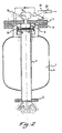
- Figure 2 illustrates the same apparatus as depicted in figure 1 with the outlet opening opened
- FIGS 1 and 2 show the same air cannon according to the invention with a valve in two different positions.
- the air cannon comprises a pressure tank 1 with an outlet opening 2 for the air from the pressure tank 1.
- the outlet opening consist of a first tube 3, which is airtightly fastened in the wall 4 of the pressure tank 1.
- a flange 5 is fastened at the end of tube 3 for easy mounting of the air cannon on a silo.
- the air cannon in this embodiment has a flange 6, on which a flange 7 is fastened.
- a second tube 8 On flange 7 a second tube 8 has been airtightly welded and concentric within this second tube 8 flange 7 supports a third tube 9 of which the diameter is smaller and the length shorter than those of the second tube 8.
- the diameter of the second tube 8 is larger than the diameter of the first tube 3.
- the first tube 3 and the third tube 9 are almost in line of each other. Between the ends of first tube 3 and third tube 9 is a space, in which a valve 10 is placed.
- Valve 10 in this embodiment comprises a metal inner disk 11 covered on its two faces by a rubber jacket 12.
- Rubber jacket 12 has two integrally formed collars 13, 14 at its circumference, one on either side of the main plane perpendicular to the axis, which collars diverge conically.
- the largest diameter of the valve collars corresponds approximately with the inner diameter of the second tube 8.
- the pressure tank 1 can be filled with air under pressure.
- valve 10 After the air cannon is released, it can be filled again with air under pressure resetting the threeway valve in the filling position and which brings valve 10 back into its initial position.
- the wall of the tubular part 8 along which the valve 10 glides also need not to be made accurate and can be manufactured of normal commercial quality seamless steel tube, so that all kinds of costly operations, such as grinding, become unnecessary.
- the inner wall of the tubular part 8 can possibly be provided with a high quality plastic coating.
- small holes can be made in the wall of the collar 14 of the valve 10, through which the air enclosed by the space bounded by the tubular part 8 and the flange 7 can flow to the space bounded by the two collars 13, 14 of the valve 10.
Landscapes
- Engineering & Computer Science (AREA)
- Mechanical Engineering (AREA)
- Filling Or Discharging Of Gas Storage Vessels (AREA)
- Catching Or Destruction (AREA)
- Air Transport Of Granular Materials (AREA)
- Control Of Fluid Pressure (AREA)
- Physical Or Chemical Processes And Apparatus (AREA)
- Respiratory Apparatuses And Protective Means (AREA)
Claims (6)
Priority Applications (1)
| Application Number | Priority Date | Filing Date | Title |
|---|---|---|---|
| AT86200896T ATE47113T1 (de) | 1985-05-24 | 1986-05-22 | Luftstossgeraet. |
Applications Claiming Priority (2)
| Application Number | Priority Date | Filing Date | Title |
|---|---|---|---|
| NL8501483 | 1985-05-24 | ||
| NL8501483A NL8501483A (nl) | 1985-05-24 | 1985-05-24 | Luchtstootapparaat. |
Publications (2)
| Publication Number | Publication Date |
|---|---|
| EP0202720A1 EP0202720A1 (de) | 1986-11-26 |
| EP0202720B1 true EP0202720B1 (de) | 1989-10-11 |
Family
ID=19846032
Family Applications (1)
| Application Number | Title | Priority Date | Filing Date |
|---|---|---|---|
| EP86200896A Expired EP0202720B1 (de) | 1985-05-24 | 1986-05-22 | Luftstossgerät |
Country Status (9)
| Country | Link |
|---|---|
| US (1) | US4703869A (de) |
| EP (1) | EP0202720B1 (de) |
| JP (1) | JPS62182087A (de) |
| AT (1) | ATE47113T1 (de) |
| AU (1) | AU580414B2 (de) |
| CA (1) | CA1298248C (de) |
| DE (1) | DE3666211D1 (de) |
| NL (1) | NL8501483A (de) |
| ZA (1) | ZA863778B (de) |
Families Citing this family (25)
| Publication number | Priority date | Publication date | Assignee | Title |
|---|---|---|---|---|
| DE3800114A1 (de) * | 1988-01-05 | 1989-07-13 | Agrichema Materialflusstechnik | Luftstossgeraet zum beseitigen von materialaufstauungen von schuettguetern in bunkern u. dgl. |
| DE3934988A1 (de) * | 1989-10-20 | 1991-04-25 | Hosch Co | Geraet zur erzeugung einer druckwelle |
| DE4236896A1 (de) * | 1992-10-31 | 1994-05-05 | Maury Hans Dietmar | Luftkanone zur Beseitigung von Schüttgutanbackungen und -stauungen |
| US5853160A (en) * | 1997-12-23 | 1998-12-29 | Martin Engineering Company | Aerator valve assembly |
| DE19743789B4 (de) * | 1997-10-02 | 2005-10-06 | Agrichema Materialflusstechnik Gmbh & Co. Kg | Vorrichtung zum stoßartigen Ausblasen von Druckluft zur Beseitigung von Materialanbackungen von Schüttgütern in Reaktionsbehältern |
| US6325605B1 (en) | 1998-11-02 | 2001-12-04 | Owens Corning Canada Inc. | Apparatus to control the dispersion and deposition of chopped fibrous strands |
| DE10101041B4 (de) * | 2001-01-11 | 2014-09-18 | Agrilux Beteiligungs Gmbh | Ventileinheit für eine Vorrichtung zum stoßartigen Ausblasen von Druckluft aus einem Druckluftspeicherbehälter zur Beseitigung von Materialanbackungen und -aufstauungen |
| US6321939B1 (en) | 2001-02-06 | 2001-11-27 | Global Mfg. Inc. | High stress blast aerator with dampended piston |
| US6749528B2 (en) * | 2001-10-09 | 2004-06-15 | Wilson S. Wengert | Apparatus and method for playing golf using a ball launcher |
| US6644294B2 (en) | 2001-11-09 | 2003-11-11 | Robert N. Christensen | Air cannon |
| US6726059B2 (en) | 2002-01-16 | 2004-04-27 | Global Manufacturing Inc. | Quick release trigger valve and blast aerator |
| US6702248B2 (en) * | 2002-01-16 | 2004-03-09 | Global Manufacturing, Inc. | Blast aerator with springless, pneumatically dampened actuator |
| DE602005020375D1 (de) * | 2004-01-14 | 2010-05-20 | Martin Eng Co | Druckbetriebene Belüftungsventilanordnung |
| US7409794B2 (en) | 2004-09-20 | 2008-08-12 | Daniel Triano | Fishing line casting and bait projectile system |
| JP2006282083A (ja) * | 2005-04-01 | 2006-10-19 | Denso Corp | 車両用空気質成分供給装置 |
| JP2006282082A (ja) * | 2005-04-01 | 2006-10-19 | Denso Corp | 車両用空気砲発生装置 |
| US20070209648A1 (en) * | 2006-03-10 | 2007-09-13 | Martin Engineering Company | Air cannon for removal of flowable material from a material handling system |
| US7837062B2 (en) * | 2006-03-10 | 2010-11-23 | Martin Engineering Company | Air cannon for removal of flowable material from a material handling system |
| US20080121220A1 (en) * | 2006-11-28 | 2008-05-29 | Disney Enterprises, Inc. | Device for producing high speed air projectiles or pulses |
| CN103363292B (zh) * | 2013-07-22 | 2015-04-08 | 广州龙之杰科技有限公司 | 可精确控制的分气气罐装置 |
| CN104828412A (zh) * | 2015-05-13 | 2015-08-12 | 濮阳市鸿宇压力容器有限公司 | 用于空气炮罐体的密封检测装置 |
| US9650206B2 (en) * | 2015-07-24 | 2017-05-16 | Dynamic Aur Inc. | Conveying systems |
| WO2018235099A1 (en) * | 2017-06-20 | 2018-12-27 | Thejo Engineering Ltd. | Air blaster |
| US11117740B2 (en) * | 2018-04-30 | 2021-09-14 | Global Mfg. Inc. | Externally controlled aerator control module and blast aerator equipped therewith |
| US10737877B2 (en) * | 2018-04-30 | 2020-08-11 | Global Manufacturing Inc. | Externally controlled retrofittable aerator control module and blast aerator equipped therewith |
Family Cites Families (4)
| Publication number | Priority date | Publication date | Assignee | Title |
|---|---|---|---|---|
| US2627873A (en) * | 1949-06-20 | 1953-02-10 | Edward F Bothe | Flush valve |
| US3788527A (en) * | 1973-01-22 | 1974-01-29 | Martin Eng Co | Quick-release aerator for introducing high pressure air into a container to facilitate dispensing |
| FR2459188A1 (fr) * | 1979-06-19 | 1981-01-09 | Ermap | Dispositif d'aeration par decharge brusque d'air comprime |
| FR2547639B1 (fr) * | 1983-06-15 | 1985-10-25 | Simoens Herve | Piston de valve d'alimentation d'une capacite puis de decharge brutale de cette capacite et valve de decharge brutale pourvue de ce piston |
-
1985
- 1985-05-24 NL NL8501483A patent/NL8501483A/nl not_active Application Discontinuation
-
1986
- 1986-05-21 JP JP61118351A patent/JPS62182087A/ja active Pending
- 1986-05-21 ZA ZA863778A patent/ZA863778B/xx unknown
- 1986-05-22 AT AT86200896T patent/ATE47113T1/de not_active IP Right Cessation
- 1986-05-22 DE DE8686200896T patent/DE3666211D1/de not_active Expired
- 1986-05-22 EP EP86200896A patent/EP0202720B1/de not_active Expired
- 1986-05-22 AU AU57697/86A patent/AU580414B2/en not_active Ceased
- 1986-05-23 CA CA000509851A patent/CA1298248C/en not_active Expired - Fee Related
- 1986-05-27 US US06/868,365 patent/US4703869A/en not_active Expired - Fee Related
Also Published As
| Publication number | Publication date |
|---|---|
| CA1298248C (en) | 1992-03-31 |
| NL8501483A (nl) | 1986-12-16 |
| ATE47113T1 (de) | 1989-10-15 |
| JPS62182087A (ja) | 1987-08-10 |
| DE3666211D1 (en) | 1989-11-16 |
| US4703869A (en) | 1987-11-03 |
| EP0202720A1 (de) | 1986-11-26 |
| AU5769786A (en) | 1986-11-27 |
| ZA863778B (en) | 1986-12-30 |
| AU580414B2 (en) | 1989-01-12 |
Similar Documents
| Publication | Publication Date | Title |
|---|---|---|
| EP0202720B1 (de) | Luftstossgerät | |
| US4197966A (en) | Air blaster or air accumulator and quick dump apparatus | |
| US4776498A (en) | Invertable pump for liquid media | |
| US4456155A (en) | Aerosol spray device | |
| US3158296A (en) | Fluid storage and discharge apparatus | |
| EP0191614B1 (de) | Ventil für unter Druck stehende Abgabebehälter | |
| US5143256A (en) | Gas accumulator and blaster apparatus | |
| US5441171A (en) | Air cannon for removing cakes of flowable material and clearing clogged areas of flowable material | |
| JPS63186014A (ja) | ダブルカートリッジ操作用の圧力媒体駆動式吐出装置 | |
| US3357604A (en) | Aerosol tilt valve | |
| US3090408A (en) | Apparatus for filling containers | |
| US3500879A (en) | Container filling apparatus | |
| US3143151A (en) | Nose-pieces for isobaric liquid-drawers | |
| JPH01294487A (ja) | 加圧ビンの充填ヘッド | |
| US5727606A (en) | Container filling machine | |
| US4015755A (en) | Electromagnetically actuatable metering valve for successive delivery of measured volumes of fluid from a fluid reservoir | |
| CN87106616A (zh) | 液体灌装设备 | |
| US4445629A (en) | Container filling machine product dispensing cylinder | |
| US3527267A (en) | Automatic container filling apparatus | |
| JPH08508961A (ja) | レセプタクルに液体ボリュームを充填する方法および装置 | |
| US4434821A (en) | Device for the automatic filling of bottles and installation containing same | |
| JPH0260593B2 (de) | ||
| US4638925A (en) | Apparatus for volumetric metering and dispensing or liquids | |
| US4146065A (en) | Method and machine for charging liquid into containers | |
| US4493349A (en) | Liquid filling machine |
Legal Events
| Date | Code | Title | Description |
|---|---|---|---|
| PUAI | Public reference made under article 153(3) epc to a published international application that has entered the european phase |
Free format text: ORIGINAL CODE: 0009012 |
|
| AK | Designated contracting states |
Kind code of ref document: A1 Designated state(s): AT BE CH DE FR GB IT LI LU NL SE |
|
| 17P | Request for examination filed |
Effective date: 19861223 |
|
| 17Q | First examination report despatched |
Effective date: 19870916 |
|
| GRAA | (expected) grant |
Free format text: ORIGINAL CODE: 0009210 |
|
| AK | Designated contracting states |
Kind code of ref document: B1 Designated state(s): AT BE CH DE FR GB IT LI LU NL SE |
|
| REF | Corresponds to: |
Ref document number: 47113 Country of ref document: AT Date of ref document: 19891015 Kind code of ref document: T |
|
| REF | Corresponds to: |
Ref document number: 3666211 Country of ref document: DE Date of ref document: 19891116 |
|
| ITF | It: translation for a ep patent filed | ||
| ET | Fr: translation filed | ||
| PLBE | No opposition filed within time limit |
Free format text: ORIGINAL CODE: 0009261 |
|
| STAA | Information on the status of an ep patent application or granted ep patent |
Free format text: STATUS: NO OPPOSITION FILED WITHIN TIME LIMIT |
|
| 26N | No opposition filed | ||
| ITTA | It: last paid annual fee | ||
| EPTA | Lu: last paid annual fee | ||
| EAL | Se: european patent in force in sweden |
Ref document number: 86200896.8 |
|
| PGFP | Annual fee paid to national office [announced via postgrant information from national office to epo] |
Ref country code: SE Payment date: 19980423 Year of fee payment: 13 Ref country code: GB Payment date: 19980423 Year of fee payment: 13 |
|
| PGFP | Annual fee paid to national office [announced via postgrant information from national office to epo] |
Ref country code: CH Payment date: 19980501 Year of fee payment: 13 |
|
| PGFP | Annual fee paid to national office [announced via postgrant information from national office to epo] |
Ref country code: AT Payment date: 19980526 Year of fee payment: 13 |
|
| PGFP | Annual fee paid to national office [announced via postgrant information from national office to epo] |
Ref country code: FR Payment date: 19980529 Year of fee payment: 13 |
|
| PGFP | Annual fee paid to national office [announced via postgrant information from national office to epo] |
Ref country code: LU Payment date: 19980604 Year of fee payment: 13 |
|
| PGFP | Annual fee paid to national office [announced via postgrant information from national office to epo] |
Ref country code: BE Payment date: 19980707 Year of fee payment: 13 |
|
| PG25 | Lapsed in a contracting state [announced via postgrant information from national office to epo] |
Ref country code: LU Free format text: LAPSE BECAUSE OF NON-PAYMENT OF DUE FEES Effective date: 19990522 Ref country code: GB Free format text: LAPSE BECAUSE OF NON-PAYMENT OF DUE FEES Effective date: 19990522 Ref country code: AT Free format text: LAPSE BECAUSE OF NON-PAYMENT OF DUE FEES Effective date: 19990522 |
|
| PG25 | Lapsed in a contracting state [announced via postgrant information from national office to epo] |
Ref country code: SE Free format text: LAPSE BECAUSE OF NON-PAYMENT OF DUE FEES Effective date: 19990523 |
|
| PG25 | Lapsed in a contracting state [announced via postgrant information from national office to epo] |
Ref country code: LI Free format text: LAPSE BECAUSE OF NON-PAYMENT OF DUE FEES Effective date: 19990531 Ref country code: CH Free format text: LAPSE BECAUSE OF NON-PAYMENT OF DUE FEES Effective date: 19990531 Ref country code: BE Free format text: LAPSE BECAUSE OF NON-PAYMENT OF DUE FEES Effective date: 19990531 |
|
| BERE | Be: lapsed |
Owner name: TECHNISCH BUREAU KNOL B.V. Effective date: 19990531 |
|
| REG | Reference to a national code |
Ref country code: CH Ref legal event code: PL |
|
| GBPC | Gb: european patent ceased through non-payment of renewal fee |
Effective date: 19990522 |
|
| EUG | Se: european patent has lapsed |
Ref document number: 86200896.8 |
|
| PG25 | Lapsed in a contracting state [announced via postgrant information from national office to epo] |
Ref country code: FR Free format text: LAPSE BECAUSE OF NON-PAYMENT OF DUE FEES Effective date: 20000131 |
|
| REG | Reference to a national code |
Ref country code: FR Ref legal event code: ST |
|
| NLS | Nl: assignments of ep-patents |
Owner name: AIR-O-BLAST B.V. |
|
| PG25 | Lapsed in a contracting state [announced via postgrant information from national office to epo] |
Ref country code: IT Free format text: LAPSE BECAUSE OF NON-PAYMENT OF DUE FEES;WARNING: LAPSES OF ITALIAN PATENTS WITH EFFECTIVE DATE BEFORE 2007 MAY HAVE OCCURRED AT ANY TIME BEFORE 2007. THE CORRECT EFFECTIVE DATE MAY BE DIFFERENT FROM THE ONE RECORDED. Effective date: 20050522 |
|
| PGFP | Annual fee paid to national office [announced via postgrant information from national office to epo] |
Ref country code: NL Payment date: 20050531 Year of fee payment: 20 |
|
| PGFP | Annual fee paid to national office [announced via postgrant information from national office to epo] |
Ref country code: DE Payment date: 20050728 Year of fee payment: 20 |
|
| NLS | Nl: assignments of ep-patents |
Owner name: AIR-O-BLAST GMBH Effective date: 20050727 |
|
| PG25 | Lapsed in a contracting state [announced via postgrant information from national office to epo] |
Ref country code: NL Free format text: LAPSE BECAUSE OF EXPIRATION OF PROTECTION Effective date: 20060522 |
|
| NLV7 | Nl: ceased due to reaching the maximum lifetime of a patent |
Effective date: 20060522 |