EP0202401B1 - Heating device - Google Patents
Heating device Download PDFInfo
- Publication number
- EP0202401B1 EP0202401B1 EP86102669A EP86102669A EP0202401B1 EP 0202401 B1 EP0202401 B1 EP 0202401B1 EP 86102669 A EP86102669 A EP 86102669A EP 86102669 A EP86102669 A EP 86102669A EP 0202401 B1 EP0202401 B1 EP 0202401B1
- Authority
- EP
- European Patent Office
- Prior art keywords
- heating resistor
- heating
- circuit
- sensor
- measuring
- Prior art date
- Legal status (The legal status is an assumption and is not a legal conclusion. Google has not performed a legal analysis and makes no representation as to the accuracy of the status listed.)
- Expired - Lifetime
Links
- 238000010438 heat treatment Methods 0.000 title claims abstract description 82
- 238000005476 soldering Methods 0.000 claims abstract description 26
- 238000005259 measurement Methods 0.000 claims description 9
- 230000001105 regulatory effect Effects 0.000 claims description 6
- 230000001276 controlling effect Effects 0.000 claims description 2
- XEEYBQQBJWHFJM-UHFFFAOYSA-N Iron Chemical compound [Fe] XEEYBQQBJWHFJM-UHFFFAOYSA-N 0.000 abstract description 8
- 229910052742 iron Inorganic materials 0.000 abstract description 4
- 238000011156 evaluation Methods 0.000 description 4
- 230000000903 blocking effect Effects 0.000 description 2
- 238000004804 winding Methods 0.000 description 2
- 238000013461 design Methods 0.000 description 1
- 238000011161 development Methods 0.000 description 1
- 230000018109 developmental process Effects 0.000 description 1
- 238000010586 diagram Methods 0.000 description 1
- 235000000396 iron Nutrition 0.000 description 1
- 238000002955 isolation Methods 0.000 description 1
- 239000000463 material Substances 0.000 description 1
- 238000000034 method Methods 0.000 description 1
Images

Classifications
-
- B—PERFORMING OPERATIONS; TRANSPORTING
- B23—MACHINE TOOLS; METAL-WORKING NOT OTHERWISE PROVIDED FOR
- B23K—SOLDERING OR UNSOLDERING; WELDING; CLADDING OR PLATING BY SOLDERING OR WELDING; CUTTING BY APPLYING HEAT LOCALLY, e.g. FLAME CUTTING; WORKING BY LASER BEAM
- B23K3/00—Tools, devices, or special appurtenances for soldering, e.g. brazing, or unsoldering, not specially adapted for particular methods
- B23K3/02—Soldering irons; Bits
- B23K3/03—Soldering irons; Bits electrically heated
- B23K3/033—Soldering irons; Bits electrically heated comprising means for controlling or selecting the temperature or power
-
- G—PHYSICS
- G05—CONTROLLING; REGULATING
- G05D—SYSTEMS FOR CONTROLLING OR REGULATING NON-ELECTRIC VARIABLES
- G05D23/00—Control of temperature
- G05D23/19—Control of temperature characterised by the use of electric means
- G05D23/20—Control of temperature characterised by the use of electric means with sensing elements having variation of electric or magnetic properties with change of temperature
- G05D23/24—Control of temperature characterised by the use of electric means with sensing elements having variation of electric or magnetic properties with change of temperature the sensing element having a resistance varying with temperature, e.g. a thermistor
- G05D23/2401—Control of temperature characterised by the use of electric means with sensing elements having variation of electric or magnetic properties with change of temperature the sensing element having a resistance varying with temperature, e.g. a thermistor using a heating element as a sensing element
Definitions
- a soldering iron is known in which the temperature of the soldering tip is measured with the aid of a sensor in the form of a thermocouple which is arranged directly behind the soldering tip in order to keep the temperature of the soldering point as constant as possible.
- the leads to the sensor and the heating resistor are routed separately to a control circuit, the output signal of the sensor forming the input variable of the control circuit. Therefore four lines are required to connect the sensor and the heating resistor to the control circuit. At most, it is possible to combine a line of the sensor with a line of the heating resistor, so that only a three-wire line is required.
- a hot-air device is also known from EP-A-0 048 772, in which the resistance value of a heating resistor is measured at the times at which this heating resistor is not supplied with feed current.
- the heating resistor has a corresponding temperature coefficient, so that the temperature can be determined on the basis of the resistance value and used as a control criterion for a temperature control circuit. In this way, a separate sensor is not required, so that corresponding supply lines can also be omitted.
- the measurement of the resistance value of a heating resistor only allows a reliable determination of the temperature of the object to be heated if the temperature of the object to be heated is always the same as the temperature of the heating resistor over its entire extent, since otherwise incorrect measurements result.
- This control element formed by the series resistor is arranged spatially behind the heating element containing the heating resistor and even more behind the soldering tip, so that the temperature of the soldering tip is only regulated with a great time delay and therefore very imprecise. Furthermore, the series resistor forming the control element must have a large resistance compared to the heating element in order to enable regulation, and the use of this heating element series resistor combination in connection with an electronic control circuit for controlling the current flowing through the heating element would not make sense.
- a soldering tool is also known from EP-A-0 102 315, in which the control circuit constantly switches between measuring and heating.
- the heating resistor is used as a temperature measuring element and the current flowing through the heating resistor during the measuring process is made with the help of a measuring resistor connected in series with the heating resistor of the evaluated.
- this measuring resistor is arranged away from the heating resistor in the control circuit and the measurement is carried out with the power actuator switched through, the voltage drop across the measuring resistor being measured and forming the input variable of the control circuit.
- the heating resistor must in turn have a PTC or NTC behavior, which is not expedient in the case of regulated soldering irons in which the working temperature of the soldering tip is to be reached quickly.
- the use of the heating resistor for measuring the temperature of a soldering tip heated by this heating resistor leads to incorrect measurements.
- the invention has for its object to provide a heating element of the type mentioned, which enables precise control of the temperature of the object to be heated, without the need for separate sensor leads.
- the senor and the heating resistor are electrically connected in series, the sensor having a low electrical resistance, so that the self-heating due to the current flowing through the heating resistor and the sensor is low. Furthermore, the sensor has one if possible Large temperature coefficient, and it is arranged as close as possible to that point of the object to be heated, the temperature of which is to be controlled.
- the senor can be formed by a measuring resistor, the temperature coefficient of which is high compared to the temperature coefficient of the heating resistor.
- the heating resistor should preferably have a negligibly small temperature coefficient.
- the temperature change of the sensor is preferably evaluated in this case in a bridge circuit, one branch of which is formed by the sensor / heating resistor combination. In this case, a measuring current is introduced into the sensor / heating resistor combination at the times when the heating resistor is not being supplied with feed current.
- the senor can be formed by a thermocouple, in which case the use of a separate measuring current source can be omitted.
- Fig. 1 an embodiment of the heating element is shown, which consists of a sensor 1 and a heating resistor 2, which are arranged inside the soldering tip 10 of a soldering iron.
- a heating resistor 2 which are arranged inside the soldering tip 10 of a soldering iron.
- an inverted arrangement can also be used, i.e. the sensor and the heating resistor can be arranged around the shaft of a soldering tip if an externally heated release tip is used.
- the sensor and the heating resistor are directly connected to each other.
- the sensor 1 is formed by a resistance coil which is arranged as close as possible to the front end of the soldering tip.
- This resistance coil could also be replaced by a thermocouple, which is also traversed by the current flowing through the heating resistor.
- the supply of the feed current and the measurement of the output voltage of the sensor is carried out via two leads 2a, 2b, so that the additional leads previously used can be omitted.
- the heating resistor 2 is very high-resistance compared to the internal resistance of the sensor, so that practically all of the heat is generated on the heating winding, whereby it is expedient when designing the sensor in the form of a resistance coil to use a material with a negligibly small temperature coefficient for the heating resistor.
- the senor should have the largest possible temperature coefficient when configured as a resistance coil.
- the senor can be arranged at a point separate from the heating resistor, specifically at a point which reproduces the actual temperature of the object to be heated as precisely as possible.
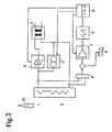
- FIG. 2 shows an embodiment of a control circuit which can be used together with the sensor / heating resistor combination according to FIG. 1.
- the entire control circuit and the heating resistor are fed from a network transformer 3, this network transformer being dispensable if no galvanic isolation from the AC network is required.
- the secondary winding of the power transformer 3 feeds the sensor-heating resistor combination 1, 2 via a power actuator 9, for example in the form of a thyristor or triac, the duty cycle of the power actuator being controlled via a synchronizing circuit 8, which in turn is controlled via a measurement signal evaluation to be explained in more detail becomes.
- This synchronizing circuit 8 controls a measuring current source 11 during the blocking times of the power actuator 9 in such a way that a measuring at these times current through the combination of the sensor 1 and the heating resistor 2 is passed.
- This sensor / heating resistor combination is also connected to an evaluation circuit 5, 7, which includes a bridge circuit 5, which evaluates temperature changes in the sensor 1.
- the output signal of the bridge circuit 5 is compared with a setpoint from a setpoint generator 6, the error voltage in an amplifier 7 and a comparator circuit 4 being compared and supplied to the synchronization circuit 8 as a control signal.
- the error amplifier 7 is also controlled by the output signal of the synchronizing circuit 8 in such a way that it is only active when the power actuator 9 is in the blocked state.
- thermocouple is used instead of the sensor 1 of the resistance type, the measuring current source 11 can be omitted and the voltage of the thermocouple can be evaluated in the bridge circuit 5 during the blocking times of the power actuator 9.
- the resistance of this sensor is very low, so that it is characterized by the heating resistor and the operating current flowing through the sensor is not significantly heated.
- the heating resistor has a temperature coefficient that is as negligible as possible, so that the influence of changes in resistance of the heating resistor in the evaluation of the measurement signal is negligible.
Landscapes
- Engineering & Computer Science (AREA)
- Mechanical Engineering (AREA)
- Physics & Mathematics (AREA)
- General Physics & Mathematics (AREA)
- Automation & Control Theory (AREA)
- Control Of Resistance Heating (AREA)
- Resistance Heating (AREA)
- Yarns And Mechanical Finishing Of Yarns Or Ropes (AREA)
- Control And Other Processes For Unpacking Of Materials (AREA)
- Heat-Pump Type And Storage Water Heaters (AREA)
- Control Of Temperature (AREA)
Abstract
Description
Aus der CH-A-523 735 ist ein Lötkolben bekannt, bei dem die Temperatur der Lötspitze mit Hilfe eines Meßfühlers in Form eines Thermoelementes gemessen wird, das unmittelbar hinter der Lötspitze angeordnet ist, um die Temperatur der Lötstelle möglichst konstant zu halten. Hierbei werden die Zuleitungen zum Meßfühler und zum Heizwiderstand getrennt zu einer Regelschaltung geführt, wobei das Ausgangssignal des Meßfühlers die Eingangsgröße der Regelschaltung bildet. Daher sind vier Leitungen zur Verbindung des Meßfühlers und des Heizwiderstandes mit der Regelschaltung erforderlich. Allenfalls ist es möglich, eine Leitung des Meßfühlers mit einer Leitung des Heizwiderstandes zu vereinigen, so daß nur eine dreidrähtige Leitungsführung erforderlich ist.From CH-A-523 735 a soldering iron is known in which the temperature of the soldering tip is measured with the aid of a sensor in the form of a thermocouple which is arranged directly behind the soldering tip in order to keep the temperature of the soldering point as constant as possible. Here, the leads to the sensor and the heating resistor are routed separately to a control circuit, the output signal of the sensor forming the input variable of the control circuit. Therefore four lines are required to connect the sensor and the heating resistor to the control circuit. At most, it is possible to combine a line of the sensor with a line of the heating resistor, so that only a three-wire line is required.
Aus der EP-A-0 048 772 ist weiterhin ein Heißluftgerät bekannt, bei dem der Widerstandswert eines Heizwiderstandes zu den Zeiten gemessen wird, zu denen dieser Heizwiderstand nicht mit Speisestrom beaufschlagt wird. Der Heizwiderstand weist einen entsprechenden Temperaturkoeffizienten auf, so daß sich anhand des Widerstandswertes die Temperatur ermitteln und als Regelkriterium für eine Temperaturregelschaltung verwenden läßt. Auf diese Weise ist ein getrennter Meßfühler nicht erforderlich, so daß auch entsprechende Zuleitungen entfallen können. Die Messung des Widerstandswertes eines Heizwiderstandes ermöglicht jedoch nur dann eine sichere Bestimmung der Temperatur des zu beheizenden Gegenstandes, wenn die Temperatur des zu beheizenden Gegenstandes immer gleich der Temperatur des Heizwiderstandes über dessen gesamte Erstreckung ist, da sich sonst Fehlmessungen ergeben. Dies ist insbesondere dann der Fall, wenn der Heizwiderstand zur Beheizung der Lötspitze verwendet wird, da in diesem Fall der Heizwiderstand eine erhebliche Länge und Abschnitte aufweist, die einen erheblichen Abstand von der Lötstelle am Ende der Löt spitze aufweisen. In diesem Fall ist es daher weiterhin zweckmäßig, zur Erzielung einer genauen Temperaturregelung gemäß der CH-A-523 735 einen getrennten Meßfühler zu verwenden, der so nah wie möglich an der Lötstelle am freien Ende der Lötspitze angeordnet ist.A hot-air device is also known from EP-A-0 048 772, in which the resistance value of a heating resistor is measured at the times at which this heating resistor is not supplied with feed current. The heating resistor has a corresponding temperature coefficient, so that the temperature can be determined on the basis of the resistance value and used as a control criterion for a temperature control circuit. In this way, a separate sensor is not required, so that corresponding supply lines can also be omitted. The measurement of the resistance value of a heating resistor, however, only allows a reliable determination of the temperature of the object to be heated if the temperature of the object to be heated is always the same as the temperature of the heating resistor over its entire extent, since otherwise incorrect measurements result. This is particularly the case when the heating resistor is used to heat the soldering tip, since in this case the heating resistor has a considerable length and sections which are at a considerable distance from the soldering point at the end of the soldering have peak. In this case, it is therefore furthermore expedient to use a separate sensor to achieve precise temperature control in accordance with CH-A-523 735, which is arranged as close as possible to the soldering point at the free end of the soldering tip.
Aus der Literaturstelle 'Product Engineering', Bd. 26, Nr. 7, Juli 1955, S. 143 'Quick Heating Solvering Gun' ist es weiterhin bekannt, bei einem Lötwerkzeug in Reihe mit einem einen niedrigen Widerstand und einen niedrigen Temperaturkoeffizienten des Widerstandswertes aufweisenden Heizwiderstand ein Regelelement in Form eines Vorwiderstandes mit einem hohen Temperaturkoeffizienten anzuordnen, um beim Einschalten eine sehr schnelle Erwärmung des Heizwiderstandes zu erzielen, wobei der Vorwiderstand durch den durch ihn fließenden Stromes zunehmend erwärmt wird und damit seinen Widerstand erhöht, so daß sich ein Gleichgewichtzustand ergibt. Jede nachfolgende Stromänderung wird durch eine Änderung des Widerstandes des das Regelelement bildenden Vorwiderstandes kompensiert, wodurch die Temperatur unabhängig von Stromschwankungen konstant gehalten wird. Dieses durch den Vorwiderstand gebildete Regelelelement ist räumlich hinter dem den Heizwiderstand enthaltenden Heizelement und erst recht hinter der Lötspitze angeordnet, so daß eine Regelung der Temperatur der Lötspitze nur mit großer zeitlicher Verzögerung und damit sehr ungenau erfolgt. Weiterhin muß der das Regelelement bildende Vorwiderstand einen verglichen mit dem Heizelement großen Widerstand aufweisen, um eine Regelung zu ermöglichen, und die Verwendung dieser Heizelement-Vorwiderstandskombination in Verbindung mit einer elektronischen Regelschaltung zur Steuerung des durch das Heizelement fließenden Stromes wäre nicht sinnvoll.From the reference 'Product Engineering', Vol. 26, No. 7, July 1955, p. 143 'Quick Heating Solvering Gun' it is also known to use a soldering tool in series with a low resistance and a low temperature coefficient of resistance Heating resistor to arrange a control element in the form of a series resistor with a high temperature coefficient in order to achieve a very rapid heating of the heating resistor when switched on, the series resistor being increasingly heated by the current flowing through it and thus increasing its resistance, so that an equilibrium state results. Each subsequent change in current is compensated for by a change in the resistance of the series resistor forming the control element, as a result of which the temperature is kept constant regardless of current fluctuations. This control element formed by the series resistor is arranged spatially behind the heating element containing the heating resistor and even more behind the soldering tip, so that the temperature of the soldering tip is only regulated with a great time delay and therefore very imprecise. Furthermore, the series resistor forming the control element must have a large resistance compared to the heating element in order to enable regulation, and the use of this heating element series resistor combination in connection with an electronic control circuit for controlling the current flowing through the heating element would not make sense.
Aus der EP-A-0 102 315 ist weiterhin ein Lötwerkzeug bekannt, bei dem die Regelschaltung ein ständiges Umschalten zwischen Messen und Heizen durchführt. Hierbei wird der Heizwiderstand als Temperatur-Meßelement ausgenutzt und der während des Meßvorganges durch den Heizwiderstand fließende Strom wird mit Hilfe eines mit dem Heizwiderstand in Reihe geschalteten Meßwiderstan des ausgewertet. Dieser Meßwiderstand ist jedoch von dem Heizwiderstand entfernt in der Regelschaltung angeordnet und die Messung erfolgt bei durchgeschaltetem Leistungsstellglied, wobei der Spannungsabfall am Meßwiderstand gemessen wird und die Eingangsgröße der Regelschaltung bildet. Hierbei muß der Heizwiderstand seinerseits ein PTC- oder ein NTC-Verhalten aufweisen, was bei geregelten Lötkolben, bei denen die Arbeitstemperatur der Lötspitze schnell erreicht werden soll, nicht zweckmäßig ist. Außerdem führt aus den vorstehend hinsichtlich der EP-A-0 048 772 angegebenen Gründen die Verwendung des Heizwiderstandes zur Messung der Temperatur einer von diesem Heizwiderstand beheizten Lötspitze zu Fehlmessungen.A soldering tool is also known from EP-A-0 102 315, in which the control circuit constantly switches between measuring and heating. Here, the heating resistor is used as a temperature measuring element and the current flowing through the heating resistor during the measuring process is made with the help of a measuring resistor connected in series with the heating resistor of the evaluated. However, this measuring resistor is arranged away from the heating resistor in the control circuit and the measurement is carried out with the power actuator switched through, the voltage drop across the measuring resistor being measured and forming the input variable of the control circuit. The heating resistor must in turn have a PTC or NTC behavior, which is not expedient in the case of regulated soldering irons in which the working temperature of the soldering tip is to be reached quickly. In addition, for the reasons given above with regard to EP-A-0 048 772, the use of the heating resistor for measuring the temperature of a soldering tip heated by this heating resistor leads to incorrect measurements.
Der Erfindung liegt die Aufgabe zugrunde, ein Heizelement der eingangs genannten Art zu schaffen, das eine genaue Regelung der Temperatur des zu beheizenden Gegenstandes ermöglicht, ohne daß getrennte Meßfühlerzuleitungen erforderlich sind.The invention has for its object to provide a heating element of the type mentioned, which enables precise control of the temperature of the object to be heated, without the need for separate sensor leads.
Diese Aufgabe wird durch die im kennzeichnenden Teil des Patentanspruchs 1 angegebenen Merkmale gelöst.This object is achieved by the features specified in the characterizing part of
Vorteilhafte Ausgestaltungen und Weiterbildungen der Erfindung ergeben sich aus den Unteransprüchen.Advantageous refinements and developments of the invention result from the subclaims.
Bei dem erfindungsgemäßen Heizelement sind der Meßfühler und der Heizwiderstand elektrisch in Reihe geschaltet, wobei der Meßfühler einen niedrigen elektrischen Widerstand aufweist, so daß die Eigenerwärmung infolge des durch den Heizwiderstand und den Meßfühler fließenden Stromes gering ist. Weiterhin weist der Meßfühler einen möglichst großen Temperaturkoeffizienten auf, und er ist so nahe wie möglich an derjenigen Stelle des zu beheizenden Gegenstandes angeordnet, dessen Temperatur geregelt werden soll.In the heating element according to the invention, the sensor and the heating resistor are electrically connected in series, the sensor having a low electrical resistance, so that the self-heating due to the current flowing through the heating resistor and the sensor is low. Furthermore, the sensor has one if possible Large temperature coefficient, and it is arranged as close as possible to that point of the object to be heated, the temperature of which is to be controlled.
Der Meßfühler kann gemäß einer Ausgestaltung der Erfindung durch einen Meßwiderstand gebildet sein, dessen Temperaturkoeffizient verglichen mit dem Temperaturkoeffizienten des Heizwiderstandes hoch ist. Der Heizwiderstand sollte vorzugsweise einen vernachlässigbar kleinen Temperaturkoeffizienten aufweisen. Die Temperaturänderung des Meßfühlers wird in diesem Fall vorzugsweise in einer Brückenschaltung ausgewertet, deren einer Zweig durch die Meßfühler-Heizwiderstands-Kombination gebildet ist. In diesem Fall wird zu den Zeiten, zu denen der Heizwiderstand nicht mit Speisestrom beaufschlagt wird, ein Meßstrom in die Meßfühler-Heizwiderstands-Kombination eingeleitet.According to one embodiment of the invention, the sensor can be formed by a measuring resistor, the temperature coefficient of which is high compared to the temperature coefficient of the heating resistor. The heating resistor should preferably have a negligibly small temperature coefficient. The temperature change of the sensor is preferably evaluated in this case in a bridge circuit, one branch of which is formed by the sensor / heating resistor combination. In this case, a measuring current is introduced into the sensor / heating resistor combination at the times when the heating resistor is not being supplied with feed current.
Gemäß einer weiteren Ausgestaltung der Erfindung kann der Meßfühler durch ein Thermoelement gebildet sein, wobei in diesem Fall die Verwendung einer getrennten Meßstromquelle entfallen kann.According to a further embodiment of the invention, the sensor can be formed by a thermocouple, in which case the use of a separate measuring current source can be omitted.
Die Erfindung wird im folgenden anhand von in der Zeichnung dargestellten Ausführungsbeispielen noch näher erläutert.The invention is explained in more detail below with reference to exemplary embodiments shown in the drawing.
In der Zeichnung zeigen:
Figur 1 eine schematische Darstellung der Meßfühler-Heizwiderstands-Kombination in Anwendung auf die Beheizung der Lötspitze eines Lötkolbens,Figur 2 ein Blockschaltbild einer Ausführungsform einer Betriebsschaltung für das Heizelement.
- FIG. 1 shows a schematic illustration of the sensor / heating resistor combination when used for heating the soldering tip of a soldering iron,
- Figure 2 is a block diagram of an embodiment of an operating circuit for the heating element.
In Fig. 1 ist eine Ausführungsform des Heizelementes dargestellt, das aus einem Meßfühler 1 und einem Heizwiderstand 2 besteht, die im Inneren der Lötspitze 10 eines Lötkolbens angeordnet sind. Selbstverständlich kann auch eine umgekehrte Anordnung verwendet werden, d.h. der Meßfühler und der Heizwiderstand können um den Schaft einer Lötspitze herum angeordnet sein, wenn eine außenbeheizte Löstspitze verwendet wird.In Fig. 1, an embodiment of the heating element is shown, which consists of a
Die Lötspitze gemäß Fig. 1 kann auch durch irgendeinen anderen zu beheizenden Gegenstand ersetzt sein.1 can also be replaced by any other object to be heated.
Wie aus Fig. 1 zu erkennen ist, sind der Meßfühler und der Heizwiderstand direkt miteinander verbunden. Gemäß Fig. 1 ist der Meßfühler 1 durch eine Widerstandswendel gebildet, die so nahe wie möglich zum vorderen Ende der Lötspitze hin angeordnet ist.As can be seen from Fig. 1, the sensor and the heating resistor are directly connected to each other. 1, the
Diese Widerstandswendel könnte auch durch ein Thermoelement ersetzt sein, das ebenfalls von dem durch den Heizwiderstand fließenden Strom durchflossen wird. Die Zuführung des Speisestroms und die Messung der Ausgangsspannung des Meßfühlers erfolgt über zwei Zuleitungen 2a, 2b, so daß die bisher verwendeten zusätzlichen Zuleitungen entfallen können.This resistance coil could also be replaced by a thermocouple, which is also traversed by the current flowing through the heating resistor. The supply of the feed current and the measurement of the output voltage of the sensor is carried out via two leads 2a, 2b, so that the additional leads previously used can be omitted.
Der Heizwiderstand 2 ist verglichen mit dem Innenwiderstand des Meßfühlers sehr hochohmig, so daß praktisch die gesamte Wärme an der Heizwicklung entsteht, wobei es bei Ausbildung des Meßfühlers in Form einer Widerstandswendel zweckmäßig ist, für den Heizwiderstand ein Material mit einem vernachlässigbar kleinen Temperaturkoeffizienten zu verwenden.The
Entsprechend sollte der Meßfühler bei Ausgestaltung als Widerstandswendel einen möglichst großen Temperaturkoeffizienten haben.Accordingly, the sensor should have the largest possible temperature coefficient when configured as a resistance coil.
Durch die getrennte Ausbildung von Meßfühler und Heizwiderstand kann der Meßfühler an einer von dem Heizwiderstand getrennten Stelle angeordnet werden, und zwar an einer Stelle, die so genau wie möglich die tatsächliche Temperatur des zu beheizenden Gegenstandes wiedergibt.Due to the separate design of the sensor and the heating resistor, the sensor can be arranged at a point separate from the heating resistor, specifically at a point which reproduces the actual temperature of the object to be heated as precisely as possible.
In Fig. 2 ist eine Ausführungsform einer Regelschaltung dargestellt, die zusammen mit der Meßfühler-Heizwiderstands-Kombination nach Fig. 1 verwendet werden kann. Die gesamte Regelschaltung und der Heizwiderstand werden aus einem Netztransformator 3 gespeist, wobei dieser Netztransformator entfallen kann, wenn keine galvanische Trennung vom Wechselspannungsnetz erforderlich ist. Die Sekundärwicklung des Netztransformators 3 speist die Meßfühler-Heizwiderstands-Kombination 1,2 über ein Leistungsstellglied 9, beispielsweise in Form eines Thyristors oder Triak, wobei die Einschaltdauer des Leistungsstellgliedes über eine Synchronisierschaltung 8 gesteuert wird, die ihrerseits über eine noch näher zu erläuternde Meßsignalauswertung angesteuert wird. Diese Synchronisierschaltung 8 steuert eine Meßstromquelle 11 während der Sperrzeiten des Leistungsstellgliedes 9 derart an, daß zu diesen Zeiten ein Meß strom durch die aus dem Meßfühler 1 und dem Heizwiderstand 2 bestehende Kombination geleitet wird. Diese Meßfühler-Heizwiderstands-Kombination ist weiterhin mit einer Auswerteschaltung 5,7 verbunden, die eine Brückenschaltung 5 einschließt, die Temperaturänderungen des Meßfühlers 1 auswertet. Das Ausgangssignal der Brückenschaltung 5 wird mit einem Sollwert von einem Sollwertgeber 6 verglichen, wobei die Fehlerspannung in einem Verstärker 7 und einer Komparatorschaltung 4 verglichen und als Steuersignal der Synchronisierschaltung 8 zugeführt wird.FIG. 2 shows an embodiment of a control circuit which can be used together with the sensor / heating resistor combination according to FIG. 1. The entire control circuit and the heating resistor are fed from a
Der Fehlerverstärker 7 wird ebenfalls durch das Ausgangssignal der Synchronisierschaltung 8 derart gesteuert, daß er nur im Sperrzustand des Leistungsstellgliedes 9 aktiv ist.The
Auf diese Weise ist eine Auswertung der durch Temperaturänderungen hervorgerufenen Widerstandsänderung des Meßfühlers möglich, ohne daß getrennte Zuleitungen zu der Meßfühlers-Heizwiderstands-Kombination erforderlich sind.In this way, an evaluation of the change in resistance of the sensor caused by temperature changes is possible without the need for separate leads to the sensor / heating resistor combination.
Wenn anstelle des Meßfühlers 1 vom Widerstandstyp ein Thermoelement verwendet wird, so kann die Meßstromquelle 11 entfallen und die Spannung des Thermoelementes während der Sperrzeiten des Leistungsstellgliedes 9 in der Brückenschaltung 5 ausgewertet werden.If a thermocouple is used instead of the
Unabhängig davon, ob der Meßfühler 1 in Form einer Widerstandswendel oder eines Thermoelementes ausgebildet ist, ist der Widerstand dieses Meßfühlers sehr gering, so daß er sich durch den durch den Heizwiderstand und den Meßfühler fließenden Betriebsstrom nicht wesentlich erwärmt. Andererseits weist der Heizwiderstand einen möglichst vernachlässigbaren Temperaturkoeffizienten auf, so daß der Einfluß von Widerstandsänderungen des Heizwiderstandes bei der Auswertung des Meßsignals vernachlässigbar ist.Regardless of whether the
Claims (7)
Priority Applications (1)
| Application Number | Priority Date | Filing Date | Title |
|---|---|---|---|
| AT86102669T ATE59713T1 (en) | 1985-04-17 | 1986-02-28 | HEATING ELEMENT. |
Applications Claiming Priority (2)
| Application Number | Priority Date | Filing Date | Title |
|---|---|---|---|
| DE19853513857 DE3513857A1 (en) | 1985-04-17 | 1985-04-17 | HEATING ELEMENT |
| DE3513857 | 1985-04-17 |
Publications (3)
| Publication Number | Publication Date |
|---|---|
| EP0202401A2 EP0202401A2 (en) | 1986-11-26 |
| EP0202401A3 EP0202401A3 (en) | 1988-08-10 |
| EP0202401B1 true EP0202401B1 (en) | 1991-01-02 |
Family
ID=6268364
Family Applications (1)
| Application Number | Title | Priority Date | Filing Date |
|---|---|---|---|
| EP86102669A Expired - Lifetime EP0202401B1 (en) | 1985-04-17 | 1986-02-28 | Heating device |
Country Status (4)
| Country | Link |
|---|---|
| EP (1) | EP0202401B1 (en) |
| JP (1) | JPH0782902B2 (en) |
| AT (1) | ATE59713T1 (en) |
| DE (2) | DE3513857A1 (en) |
Families Citing this family (9)
| Publication number | Priority date | Publication date | Assignee | Title |
|---|---|---|---|---|
| IT1207334B (en) * | 1986-11-05 | 1989-05-17 | Santoro Giovanni Francolini Er | LIGHTWEIGHT WELDER, ESPECIALLY SUITABLE FOR TIN SILVER WELDING |
| DE3704534C1 (en) * | 1987-02-13 | 1988-10-27 | Bert Dr-Ing Kueppers | Circuit arrangement for temperature-dependent heating elements |
| JPS6427771A (en) * | 1987-07-21 | 1989-01-30 | Toshiba Corp | Reflow power source |
| DE3738155A1 (en) * | 1987-11-10 | 1989-05-18 | Zeva Gmbh | SOLDERING DEVICE, CONSISTING OF AT LEAST ONE SOLDERING IRON |
| DE3812139A1 (en) * | 1988-04-12 | 1989-10-26 | Sachs Ersa Kg | METHOD AND DEVICE FOR OPERATING A SOLDERING STATION |
| DE3830415A1 (en) * | 1988-09-07 | 1990-03-15 | Sachs Ersa Kg | TERMINAL COMPENSATION MEASUREMENT FOR TEMPERATURE CONTROLLERS AND MEASURING DEVICES |
| ES2157168B1 (en) * | 1999-09-23 | 2002-08-01 | Jbc Ind S A | ELECTRIC WELDER. |
| JP5975652B2 (en) * | 2012-01-17 | 2016-08-23 | 太洋電機産業株式会社 | Solder blotter |
| WO2016114263A1 (en) * | 2015-01-13 | 2016-07-21 | 太洋電機産業株式会社 | Soldering iron |
Family Cites Families (11)
| Publication number | Priority date | Publication date | Assignee | Title |
|---|---|---|---|---|
| CH440484A (en) * | 1964-12-08 | 1967-07-31 | Dreamland Electrical Appliance | Device for regulating the temperature of an electric heater |
| CH523735A (en) * | 1970-04-22 | 1972-06-15 | Hydrel Ag Maschf | Electronically power-controlled and temperature-controlled soldering iron |
| JPS50106251A (en) * | 1973-08-06 | 1975-08-21 | ||
| DE2726458A1 (en) * | 1977-06-11 | 1979-01-04 | Bosch Gmbh Robert | ELECTRICALLY POWERED RAPID HEATING DEVICE |
| JPS5425249A (en) * | 1977-07-27 | 1979-02-26 | Kono Shiyouzou | Temperatureeadjustable electric soldering iron |
| JPS56112085A (en) * | 1980-02-07 | 1981-09-04 | Hakko Denki Seisakusho Kk | Method of controlling temperature |
| JPS6014821Y2 (en) * | 1981-01-29 | 1985-05-11 | 東陶機器株式会社 | Freeze prevention device in piping |
| JPS5819890A (en) * | 1981-07-28 | 1983-02-05 | ユルダ・フライ | Heating cartridge with sensor |
| JPS5825445U (en) * | 1981-08-12 | 1983-02-18 | ナショナル住宅産業株式会社 | Peripheral storage structure of flooring material |
| DE3228202C2 (en) * | 1982-07-28 | 1990-11-15 | ERSA Ernst Sachs KG, GmbH & Co, 6980 Wertheim | Circuit arrangement for regulating the operating temperature of the heating element of an electrical soldering device, in particular a soldering iron |
| JPS6012689A (en) * | 1983-06-30 | 1985-01-23 | 杉森 英夫 | Heater drive controller |
-
1985
- 1985-04-17 DE DE19853513857 patent/DE3513857A1/en not_active Withdrawn
-
1986
- 1986-02-28 EP EP86102669A patent/EP0202401B1/en not_active Expired - Lifetime
- 1986-02-28 AT AT86102669T patent/ATE59713T1/en not_active IP Right Cessation
- 1986-02-28 DE DE8686102669T patent/DE3676343D1/en not_active Expired - Lifetime
- 1986-04-16 JP JP61087520A patent/JPH0782902B2/en not_active Expired - Lifetime
Also Published As
| Publication number | Publication date |
|---|---|
| JPS61279086A (en) | 1986-12-09 |
| ATE59713T1 (en) | 1991-01-15 |
| DE3513857A1 (en) | 1986-10-30 |
| JPH0782902B2 (en) | 1995-09-06 |
| DE3676343D1 (en) | 1991-02-07 |
| EP0202401A3 (en) | 1988-08-10 |
| EP0202401A2 (en) | 1986-11-26 |
Similar Documents
| Publication | Publication Date | Title |
|---|---|---|
| DE3228202C2 (en) | Circuit arrangement for regulating the operating temperature of the heating element of an electrical soldering device, in particular a soldering iron | |
| DE3812139C2 (en) | ||
| DE2827928C2 (en) | Starting switching device for diesel internal combustion engines | |
| EP0004035B1 (en) | Soldering device with temperature control | |
| DE2139999A1 (en) | Status sensor circuit in bridge arrangement | |
| EP0202401B1 (en) | Heating device | |
| EP0561798B1 (en) | Temperature regulator for soldering and unsoldering equipment | |
| DE3014955A1 (en) | TEMPERATURE STABILIZED CHAMBER, ESPECIALLY FOR A CRYSTAL OSCILLATOR | |
| EP0064610B1 (en) | Electrically heated soldering tool | |
| DE3327340A1 (en) | HEATING ARRANGEMENT FOR THERMALLY GLUING PLASTIC FILMS AND METHOD FOR OPERATING THE HEATING ARRANGEMENT | |
| DE1279813B (en) | Two-point controller with a thyratron as an actuator | |
| DE2908147C2 (en) | Room unit that is connected to a weather-compensated controller for regulating the flow temperature via cables | |
| DE2643658B2 (en) | Temperature control device | |
| EP0048772B1 (en) | Hot-air device for desoldering, soldering, shrinking and the like | |
| DE2731014C3 (en) | Device for controlling a three-phase electric arc furnace | |
| DE3042947A1 (en) | CIRCUIT ARRANGEMENT | |
| DE3712648C2 (en) | ||
| DE3022854C1 (en) | Temperature controlled soldering iron | |
| DE2062713A1 (en) | Electronic charge control, consisting of a central control unit and a number of heat storage ovens equipped with charge controllers | |
| DE3145512C2 (en) | Arrangement for controlling the heating power generated by a resistor | |
| DE2153408A1 (en) | ELECTRONIC MULTI-CIRCUIT TEMPERATURE CONTROLLER | |
| DE1159109B (en) | Equipment for electric hotplates | |
| DE2632668B1 (en) | Fuel burner control for central heating system - has diode net work to control voltages in rated value branch of a measurement bridge | |
| DE3030295A1 (en) | Short circuit detection for thermo-element connection - uses operational amplifier to compare thermal voltage and reference voltage | |
| DE3912417A1 (en) | Electronic room temp. controller relay control transistor - has control voltage influenced by capacitor voltage to give rapid response to temp. variations |
Legal Events
| Date | Code | Title | Description |
|---|---|---|---|
| PUAI | Public reference made under article 153(3) epc to a published international application that has entered the european phase |
Free format text: ORIGINAL CODE: 0009012 |
|
| AK | Designated contracting states |
Kind code of ref document: A2 Designated state(s): AT BE CH DE FR GB IT LI LU NL SE |
|
| PUAL | Search report despatched |
Free format text: ORIGINAL CODE: 0009013 |
|
| AK | Designated contracting states |
Kind code of ref document: A3 Designated state(s): AT BE CH DE FR GB IT LI LU NL SE |
|
| 17P | Request for examination filed |
Effective date: 19880829 |
|
| 17Q | First examination report despatched |
Effective date: 19891214 |
|
| GRAA | (expected) grant |
Free format text: ORIGINAL CODE: 0009210 |
|
| AK | Designated contracting states |
Kind code of ref document: B1 Designated state(s): AT BE CH DE FR GB IT LI LU NL SE |
|
| REF | Corresponds to: |
Ref document number: 59713 Country of ref document: AT Date of ref document: 19910115 Kind code of ref document: T |
|
| ITF | It: translation for a ep patent filed | ||
| REF | Corresponds to: |
Ref document number: 3676343 Country of ref document: DE Date of ref document: 19910207 |
|
| ET | Fr: translation filed | ||
| GBT | Gb: translation of ep patent filed (gb section 77(6)(a)/1977) | ||
| PLBE | No opposition filed within time limit |
Free format text: ORIGINAL CODE: 0009261 |
|
| STAA | Information on the status of an ep patent application or granted ep patent |
Free format text: STATUS: NO OPPOSITION FILED WITHIN TIME LIMIT |
|
| 26N | No opposition filed | ||
| EPTA | Lu: last paid annual fee | ||
| EAL | Se: european patent in force in sweden |
Ref document number: 86102669.8 |
|
| PGFP | Annual fee paid to national office [announced via postgrant information from national office to epo] |
Ref country code: LU Payment date: 20000210 Year of fee payment: 15 |
|
| PGFP | Annual fee paid to national office [announced via postgrant information from national office to epo] |
Ref country code: NL Payment date: 20001222 Year of fee payment: 16 |
|
| PGFP | Annual fee paid to national office [announced via postgrant information from national office to epo] |
Ref country code: GB Payment date: 20010104 Year of fee payment: 16 |
|
| PGFP | Annual fee paid to national office [announced via postgrant information from national office to epo] |
Ref country code: AT Payment date: 20010105 Year of fee payment: 16 |
|
| PGFP | Annual fee paid to national office [announced via postgrant information from national office to epo] |
Ref country code: SE Payment date: 20010201 Year of fee payment: 16 Ref country code: FR Payment date: 20010201 Year of fee payment: 16 |
|
| PG25 | Lapsed in a contracting state [announced via postgrant information from national office to epo] |
Ref country code: LU Free format text: LAPSE BECAUSE OF NON-PAYMENT OF DUE FEES Effective date: 20010228 |
|
| PGFP | Annual fee paid to national office [announced via postgrant information from national office to epo] |
Ref country code: BE Payment date: 20010313 Year of fee payment: 16 |
|
| PGFP | Annual fee paid to national office [announced via postgrant information from national office to epo] |
Ref country code: CH Payment date: 20010321 Year of fee payment: 16 |
|
| REG | Reference to a national code |
Ref country code: GB Ref legal event code: IF02 |
|
| PG25 | Lapsed in a contracting state [announced via postgrant information from national office to epo] |
Ref country code: LI Free format text: LAPSE BECAUSE OF NON-PAYMENT OF DUE FEES Effective date: 20020228 Ref country code: GB Free format text: LAPSE BECAUSE OF NON-PAYMENT OF DUE FEES Effective date: 20020228 Ref country code: CH Free format text: LAPSE BECAUSE OF NON-PAYMENT OF DUE FEES Effective date: 20020228 Ref country code: BE Free format text: LAPSE BECAUSE OF NON-PAYMENT OF DUE FEES Effective date: 20020228 Ref country code: AT Free format text: LAPSE BECAUSE OF NON-PAYMENT OF DUE FEES Effective date: 20020228 |
|
| PG25 | Lapsed in a contracting state [announced via postgrant information from national office to epo] |
Ref country code: SE Free format text: LAPSE BECAUSE OF NON-PAYMENT OF DUE FEES Effective date: 20020301 |
|
| BERE | Be: lapsed |
Owner name: COOPER INDUSTRIES INC. Effective date: 20020228 |
|
| PG25 | Lapsed in a contracting state [announced via postgrant information from national office to epo] |
Ref country code: NL Free format text: LAPSE BECAUSE OF NON-PAYMENT OF DUE FEES Effective date: 20020901 |
|
| REG | Reference to a national code |
Ref country code: CH Ref legal event code: PL |
|
| GBPC | Gb: european patent ceased through non-payment of renewal fee |
Effective date: 20020228 |
|
| EUG | Se: european patent has lapsed |
Ref document number: 86102669.8 |
|
| PG25 | Lapsed in a contracting state [announced via postgrant information from national office to epo] |
Ref country code: FR Free format text: LAPSE BECAUSE OF NON-PAYMENT OF DUE FEES Effective date: 20021031 |
|
| NLV4 | Nl: lapsed or anulled due to non-payment of the annual fee |
Effective date: 20020901 |
|
| REG | Reference to a national code |
Ref country code: FR Ref legal event code: ST |
|
| PG25 | Lapsed in a contracting state [announced via postgrant information from national office to epo] |
Ref country code: IT Free format text: LAPSE BECAUSE OF NON-PAYMENT OF DUE FEES Effective date: 20050228 |
|
| PGFP | Annual fee paid to national office [announced via postgrant information from national office to epo] |
Ref country code: DE Payment date: 20050228 Year of fee payment: 20 |