EP0201777A2 - Device for discharging bulk material from a container - Google Patents
Device for discharging bulk material from a container Download PDFInfo
- Publication number
- EP0201777A2 EP0201777A2 EP86105700A EP86105700A EP0201777A2 EP 0201777 A2 EP0201777 A2 EP 0201777A2 EP 86105700 A EP86105700 A EP 86105700A EP 86105700 A EP86105700 A EP 86105700A EP 0201777 A2 EP0201777 A2 EP 0201777A2
- Authority
- EP
- European Patent Office
- Prior art keywords
- lifting
- support tube
- drive
- container
- lifting rod
- Prior art date
- Legal status (The legal status is an assumption and is not a legal conclusion. Google has not performed a legal analysis and makes no representation as to the accuracy of the status listed.)
- Granted
Links
Images


Classifications
-
- B—PERFORMING OPERATIONS; TRANSPORTING
- B65—CONVEYING; PACKING; STORING; HANDLING THIN OR FILAMENTARY MATERIAL
- B65G—TRANSPORT OR STORAGE DEVICES, e.g. CONVEYORS FOR LOADING OR TIPPING, SHOP CONVEYOR SYSTEMS OR PNEUMATIC TUBE CONVEYORS
- B65G53/00—Conveying materials in bulk through troughs, pipes or tubes by floating the materials or by flow of gas, liquid or foam
- B65G53/34—Details
- B65G53/40—Feeding or discharging devices
-
- B—PERFORMING OPERATIONS; TRANSPORTING
- B65—CONVEYING; PACKING; STORING; HANDLING THIN OR FILAMENTARY MATERIAL
- B65D—CONTAINERS FOR STORAGE OR TRANSPORT OF ARTICLES OR MATERIALS, e.g. BAGS, BARRELS, BOTTLES, BOXES, CANS, CARTONS, CRATES, DRUMS, JARS, TANKS, HOPPERS, FORWARDING CONTAINERS; ACCESSORIES, CLOSURES, OR FITTINGS THEREFOR; PACKAGING ELEMENTS; PACKAGES
- B65D88/00—Large containers
- B65D88/54—Large containers characterised by means facilitating filling or emptying
- B65D88/64—Large containers characterised by means facilitating filling or emptying preventing bridge formation
- B65D88/68—Large containers characterised by means facilitating filling or emptying preventing bridge formation using rotating devices
Definitions
- the invention relates to a device for bulk material discharge from a container with a metering body arranged in a container outlet, which is connected to a lifting drive via an upwardly extending lifting rod.
- the lifting movements of the metering body serve primarily to meter the bulk material discharge.
- the stroke movements are controlled according to the stroke size and / or stroke frequency.
- the stroke movements of the dosing body also cause a constant loosening of the bulk material in the area of the container outlet. so that even more difficult bulk material that tends to form bridges can be discharged.
- the object of the invention is therefore to design a device of the type mentioned at the outset in such a way that even very difficult bulk goods can be discharged with it, for example gypsum with an increased moisture content.
- This object is achieved in that agitator blades are arranged in the container above the container outlet, that the agitator blades are attached to a rotatably mounted support tube concentrically surrounding the lifting rod, which is connected to a rotary drive, and that the support tube by a lifting drive for continuous lifting movements is drivable.
- Rotatable tubular blades in the lower region of bulk goods containers are known in many embodiments as an effective measure to facilitate bulk material discharge.
- the support tube carrying the agitator blades can be connected to a separate lifting drive or can be driven together with the dosing body by a common lifting drive.
- the common stroke drive of the agitator blades with the rotating body can be achieved in a structurally particularly simple manner in that the supporting tube carrying the tubular blades is axially connected to the lifting rod and is rotatably mounted on the lifting rod Carrier tube rotates while the lifting rod is not rotating.
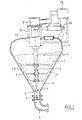
- a container 2 intended for receiving a bulk material 1, for example gypsum with an increased moisture content, has a container section 3 which tapers in the shape of a truncated cone and ends in a container outlet 4.
- a pipe 6 for the further transport of the bulk material 1 is connected to the container outlet 4 via a sealing cap 5, which is connected, for example, to a pneumatic conveying line Lift drive 9, for example a pressure-operated cylinder is connected.
- a control device 10 controls the stroke movements of the metering body 7 via the stroke drive 9 and the stroke rod 8 according to size and / or frequency.
- agitator blades 12 are arranged at the lower end and pass through the lower region of the container 2 during a rotary movement in order to loosen up the bulk material 1.
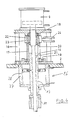
- the support tube 11 is connected at its upper end to a sleeve 13 which is rotatably mounted on the lifting rod 8 via axial bearings 14, 15, but is axially fixed. During the lifting movements, which the lifting rod 8 executes by means of the lifting drive 9, the support tube 11 is taken along in this way.
- a driving bush 17 is rotatably mounted in radial bearings 18, 19.
- the driving sleeve 17 surrounds the lifting rod 8 and the upper end of the sleeve 13 and has a plurality of longitudinal slots 20, into each of which a guide roller 21 projects, which is connected to the sleeve 13. In this way, the support tube 11 and the bushing 13 connected to it can be moved longitudinally in the driving bushing 17, which is arranged concentrically thereto, but non-rotatably.
- the inner ring of a freewheel mechanism 22 is non-rotatably connected to an upper shoulder of the driving sleeve 17 by a feather key 23.
- the outer ring of the freewheel mechanism 22 is connected via a lever 24 to a pressure-actuated cylinder 25 (FIG. 1), which forms a rotary drive for the support tube 11 and the agitator blades 12.
- the control device 10 controls the cylinder 25 in time with the stroke drive 9. With each work cycle, the driving sleeve 17 and thus the support tube 11 perform a turning step. At the same time, the support tube 11 is carried along by the lifting movement of the lifting rod 8 taking place in the same cycle.
- the control device 10 can also be operated in such a way that the rotary drive 25 of the agitator blades 12 deviates in its clock frequency from the stroke frequency of the stroke drive 9. For example, every second stroke of the metering body 7 can have an optionally longer or shorter rotational stroke of the agitator blades 12. This control and coordination of the stroke movement of the metering body 7 and the rotary movements of the agitator blades 12 takes place as a function of the properties of the bulk material 1 to be discharged in each case.
- FIG. 3 shows a modified embodiment of a container with a dosing and discharge device in a representation similar to FIG. 1.
- the same components are provided with the same reference numerals as in Fig. 1.
- the embodiment shown in FIG. 3 differs from the embodiment according to FIG. 1 only in that the lifting drive of the support tube 11 carrying the agitator blades 12 'is not effected by the lifting drive 9 of the lifting rod 8 for the metering body 7, but by a separate lifting drive 26 , which is formed, for example, by a pressure-operated cylinder, which is arranged at the lower end of the frame 16.
- the stroke drive 26 is also controlled by the control device 10. Details are shown in FIG. 4.
- the support tube 11 (FIG. 4) is connected at its upper end to the sleeve 13, which extends through a cylinder 27, which is attached below the frame 16.
- a piston 28 is sealingly guided in the cylinder 27 and is connected to the sleeve 13. If the top or bottom of the piston 28 is alternately struck with a pressure medium in the cylinder 27, the piston 28 performs lifting movements. He takes the sleeve 13 and the agitator blades 12 'with the support tube 11.
- the connection of the piston 28 to the sleeve 13 can be carried out so that the sleeve 13 can rotate in the piston 28.
- a lifting drive 26 which is independent of the lifting drive 9 of the dosing body 7 is provided for the stirring blades 12 ', different lifting heights and lifting frequencies can be selected for the lifting movements of the dosing body 7 and the stirring blades 12'. This has proven to be particularly advantageous for the discharge of difficult bulk goods. Some bulk materials that are particularly difficult to discharge, such as moist gypsum, can only be discharged under certain operating conditions if the lifting movements of the stirring blades 12 ′ are controlled independently of the lifting movements of the metering body 7, and the lifting movements of the stirring blades 12 may also be required at times 'switch off completely.
- Fig. 3 shows that the agitator blades 12 'in the lower stroke position lie close to the container wall of the truncated cone-shaped container section 3.
- the agitator blades 12 ' are here designed to be cutting-like, their cutting edge moving closely along the container wall during a rotary movement in the lower stroke position.
Abstract
Description
Die Erfindung betrifft eine Vorrichtung zum Schüttgutaustrag aus einem Behälter mit einem in einem Behälterauslaß angeordneten Dosierkörper, der über eine sich nach oben erstreckende Hubstange mit einem Hubantrieb verbunden ist.The invention relates to a device for bulk material discharge from a container with a metering body arranged in a container outlet, which is connected to a lifting drive via an upwardly extending lifting rod.
Bei einer solchen bekannten Vorrichtung (DE-PS 25 33 070) dienen die Hubbewegungen des Dosierkörpers in erster Linie zu einer Dosierung des Schüttgutaustrags. Zu diesem Zweck werden die Hubbewegungen nach Hubgröße und/oder Hubfrequenz gesteuert. Außerdem bewirken die Hubbewegungen des Dosierkörpers aber auch eine ständige Auflockerung des Schüttgutes im Bereich des Behälterauslasses. so daß auch schwierigeres Schüttgut, das zu einer Brückenbildung neigt, ausgetragen werden kann. Es gibt jedoch Schüttgüter, die so schwierig auszutragen sind, daß sie auch durch die Hubbewegungen des Dosierkörpers im Behälterauslaß und gfs. eine zusätzliche seitliche Belüftung im unteren Bereich des Behälters nicht ausreichend gelockert werden können, um einen zufreidenstellenden Schüttgutaustrag zu ermöglichen.In such a known device (DE-PS 25 33 070), the lifting movements of the metering body serve primarily to meter the bulk material discharge. For this purpose, the stroke movements are controlled according to the stroke size and / or stroke frequency. In addition, the stroke movements of the dosing body also cause a constant loosening of the bulk material in the area of the container outlet. so that even more difficult bulk material that tends to form bridges can be discharged. However, there are bulk materials that are so difficult to discharge that they are also due to the lifting movements of the dosing body in the container outlet and gfs. an additional side ventilation in the lower area of the container cannot be loosened sufficiently to enable bulk material to be discharged.
Aufgabe der Erfindung ist es daher, ein Vorrichtung der eingangs genannten Gattung so auszugestalten, daß damit auch sehr schwierige Schüttgüter ausgetragen werden können, beispielsweise Gips mit einem erhöhten Feuchtigkeitsanteil. Diese Aufgabe wird erfindungsgemäß dadurch gelöst, daß im Behälter oberhalb des Behälterauslasses Rührflügel angeordnet sind, daß die Rührflügel an einem die Hubstange konzentrisch umgebenden, drehbar gelagerten Tragrohr befestigt sind, das mit einem Drehantrieb verbunden ist, und daß das Tragrohr durch einen Hubantrieb zu kontinuierlichen Hubbewegungen antreibbar ist. Drehbar angetriebene Rohrflügel im unteren Bereich von Schüttgutbehältem sind als wirksame Maßnahme zur Erleichterung des Schüttgutaustrags in zahlreichen Ausführungsformen bekannt. Es hat sich jedoch gezeigt, daß bei besonders schwierigem Schüttgut auch die sich drehenden Rührflügel keine ausreichende Auflockerung des Schüttgutes bewirken können, um einen - kontinuierlichen Schüttgutaustrag zu ermöglichen. Erst durch die der Drehbewegung überlagerte Hubbewegung der Rührflügel wird es möglich, schwieriges Schüttgut, wie beispielsweise feuchten Gips, kontinuierlich und dosiert aus dem Behälter auszutragen. Brückenbildungen oder sonstiges Verstopfen werden wirksam verhindert.The object of the invention is therefore to design a device of the type mentioned at the outset in such a way that even very difficult bulk goods can be discharged with it, for example gypsum with an increased moisture content. This object is achieved in that agitator blades are arranged in the container above the container outlet, that the agitator blades are attached to a rotatably mounted support tube concentrically surrounding the lifting rod, which is connected to a rotary drive, and that the support tube by a lifting drive for continuous lifting movements is drivable. Rotatable tubular blades in the lower region of bulk goods containers are known in many embodiments as an effective measure to facilitate bulk material discharge. However, it has been shown that, in the case of particularly difficult bulk material, the rotating agitator blades cannot sufficiently loosen the bulk material in order to enable continuous bulk material discharge. It is only through the stroke movement of the agitator blades, which is superimposed on the rotary movement, that it is possible to discharge difficult bulk goods, such as moist plaster, continuously and in a metered manner from the container. Bridges or other blockages are effectively prevented.
Das die Rührflügel tragende Tragrohr kann mit einem gesonderten Hubantrieb verbunden sein oder zusammen mit dem Dosierkörper durch einen gemeinsamen Hubantrieb angetrieben werden.The support tube carrying the agitator blades can be connected to a separate lifting drive or can be driven together with the dosing body by a common lifting drive.
Der gemeinsame Hubantrieb der Rührflügel mit dem Drehkörper läßt sich in konstruktiv besonders einfacher Weise dadurch erreichen, daß das die Rohrflügel tragende Tragrohr mit der Hubstange axial verbunden und an der Hubstange drehbar gelagert ist Die Hubstange nimmt dadurch das Tragrohr zu den Hubbewegungen mit, wobei sich das Tragrohr dreht, während die Hubstange keine Drehbewegungen ausführt.The common stroke drive of the agitator blades with the rotating body can be achieved in a structurally particularly simple manner in that the supporting tube carrying the tubular blades is axially connected to the lifting rod and is rotatably mounted on the lifting rod Carrier tube rotates while the lifting rod is not rotating.
Weitere vorteilhafte Ausgestaltungen des Erfindungsgedankens sind Gegenstand weiterer Unteransprüche.Further advantageous embodiments of the inventive concept are the subject of further dependent claims.
Die Erfindung wird nachfolgend an einem Ausführungsbeispiel nähert erläuter, das in der Zeichnung dargestellt ist. Es zeigt:
- Fig. 1 im senkrechten Schnitt einen Behälter mit einer Dosier-und Austragseinrichtung,
- Fig. 2 einen vergrößerten Teilschnitt durch den Hubund Drehantrieb der Vorrichtung nach Fig. 1,
- Fig. 3 eine andere Ausführungsform in einem Schnitt ähnlich der Fig. 1 und
- Fig. 4 einen vergrößerten Teilschnitt ähnlich der Fig. 2 durch die Hubantriebe un den Drehantrieb der Vorrichtung nach Fig. 3.
- 1 in vertical section a container with a dosing and discharge device,
- 2 shows an enlarged partial section through the lifting and rotary drive of the device according to FIG. 1,
- Fig. 3 shows another embodiment in a section similar to FIGS. 1 and
- 4 shows an enlarged partial section similar to FIG. 2 through the lifting drives and the rotary drive of the device according to FIG. 3.
Ein zur Aufnahme eines Schüttgutes 1, beispielsweise Gips mit einem erhöhten Feuchtigkeitsgehalt, bestimmter Behälter 2 weist einen sich nach unten kegelstumpfförmig verjüngenden Behälterabschnitt 3 auf, der in einem Behälterauslaß 4 endet. An den Behälterauslaß 4 ist über eine Verschlußkappe 5 eine Rohrleitung 6 für den weiteren Transport des Schüttgutes 1 angeschlossen, die beispielsweise mit einer pneumatischen Förderleitung verbunden ist Im Behälterauslaß 4 ist ein doppelkegelförmiger Dosierkörper 7 angeordnet, der über eine senkrecht nach oben ragende Hubstange 8 mit einem Hubantrieb 9, beispielsweise einem druckmittelbetätigten Zylinder verbunden ist. Eine Steuereinrichtung 10 steuert die Hubbewegungen des Dosierkörpers 7 über den Hubantrieb 9 und die Hubstange 8 nach Größe und/oder Frequenz.A
An einem die Hubstange 8 konzentrisch umgebenden Tragrohr 11 sind am unteren Ende Rührflügel 12 angeordnet, die bei einer Drehbewegung den unteren Bereich des Behälters 2 durchlaufen, um das Schüttgut 1 aufzulockern.On a
Wie in Fig. 2 in Einzelheiten dargestellt ist, ist das Tragrohr 11 an seinem oberen Ende mit einer Hülse 13 verbunden, die über Axiallager 14, 15 an der Hubstange 8 drehbar gelagert, jedoch axial festgelegt ist. Bei den Hubbewegungen, die die Hubstange 8 mittels des Hubantriebs 9 ausführt, wird auf diese Weise das Tragrohr 11 mitgenommen.As shown in Fig. 2 in detail, the
In einem auf den Behälter 2 aufgesetzten Gestell 16 ist eine Mitnahmebüchse 17 in Radiallagern 18, 19 drehbar gelagert. Die Mitnahmebüchse 17 umgibt die Hubstange 8 und das obere Ende der Hülse 13 und weist mehrere Längsschlitze 20 auf, in die jeweils eine Führungsrolle 21 ragt, die mit der Büchse 13 verbunden ist. Auf diese Weise ist das Tragrohr 11 und die damit verbundene Büchse 13 in der konzentrisch dazu angeordneten Mitnahmebüchse 17 längsverschiebbar, jedoch undrehbar geführt.In a
Der Innenring eines Freilaufgesperres 22 ist undrehbar mit einem oberen Ansatz der Mitnahmebüchse 17 durch eine Paßfeder 23 verbunden. Der Außenring des Freilaufgesperres 22 ist über einen Hebel 24 mit einem druckmittelbetätigten Zylinder 25 (Fig. 1) verbunden, der einen Drehantrieb für das Tragrohr 11 und die Rührflügel 12 bildet.The inner ring of a
Die Steuereinrichtung 10 steuert den Zylinder 25 im Takt des Hubantriebs 9. Bei jedem Arbeitstakt führt die Mitnahmebüchse 17 und damit das Tragrohr 11 einen Drehschritt aus. Zugleich wird das Tragrohr 11 durch die im gleichen Takt erfolgende Hubbewegung der Hubstange 8 mitgenommen.The
Die Steuereinrichtung 10 kann auch so betätigt werden, daß der Drehantrieb 25 der Rührflügel 12 in seiner Taktfrequenz von der Hubfrequenz des Hubantriebs 9 abweicht. Beispielsweise kann auf jeden zweiten Hub des Dosierkörpers 7 ein wahlweise längerer oder kürzerer Drehhub der Rührflügel 12 entfallen. Diese Steuerung und Abstimmung der Hubbewegung des Dosierkörpers 7 und der Drehbewegungen der Rührflügel 12 erfolgt in Abhängigkeit von den Eigenschaften des jeweils auszutragenden Schüttgutes 1.The
Fig. 3 zeigt in einer der Fig. 1 ähnlichen Darstellungsform eine abgewandelte Ausführungsform eines Behälters mit einer Dosier-und Austragseinrichtung. Gleiche Bauteile sind mit gleichen Bezugszeichen wie in Fig. 1 versehen. Die in Fig. 3 dargestellte Ausführungsform unterscheidet sich von der Ausführungsform nach Fig. 1 nur dadurch, daß der Hubantrieb des die Rührflügel 12' tragenden Tragrohres 11 nicht durch den Hubantrieb 9 der Hubstange 8 für den Dosierkörper 7 erfolgt, sondern durch einen gesonderten Hubantrieb 26, der beispielsweise von einem druckmittelbetätigten Zylinder gebildet wird, der am unteren Ende des Gestells 16 angeordnet ist. Der Hubantrieb 26 wird ebenfalls von der Steuereinrichtung 10 gesteuert. Einzelheiten sind in Fig. 4 dargestellt.3 shows a modified embodiment of a container with a dosing and discharge device in a representation similar to FIG. 1. The same components are provided with the same reference numerals as in Fig. 1. The embodiment shown in FIG. 3 differs from the embodiment according to FIG. 1 only in that the lifting drive of the
Das Tragrohr 11 (Fig. 4) ist an seinem oberen Ende mit der Hülse 13 verbunden, die sich durch einen Zylinder 27 hindurch erstreckt, der unterhalb des Gestells 16 angebracht ist. Im Zylinder 27 ist ein Kolben 28 dichtend geführt, der mit der Hülse 13 verbunden ist. Wenn im Zylinder 27 die Oberseite bzw. die Unterseite des Kolbens 28 abwechselnd mit einem Druckmittel beauf schlagt wird, führt der Kolben 28 Hubbewegungen auf. Dabei nimmit er die Hülse 13 und über das Tragrohr 11 die Rührflügel 12' mit. Die Verbindung des Kolbens 28 mit der Hülse 13 kann so ausgeführt sein, daß sich die Hülse 13 im Kolben 28 drehen kann.The support tube 11 (FIG. 4) is connected at its upper end to the
Da bei dieser Ausführungsform für die Rührflügel 12' ein vom Hubantrieb 9 des Dosierkörpers 7 unabhängiger Hubantrieb 26 vorgesehen ist, können für die Hubbewegungen des Dosierkörpers 7 und der Rührflügel 12' unterschiedliche Hubhöhen und Hubfrequenzen gewählt werden. Dies hat sich für den Austrag schwieriger Schüttgüter als besonders vorteilhaft erwiesen. Manche besonders schwierig auszutragende Schüttgüter, wie beispielsweise feuchter Gips, lassen sich unter bestimmten Betriebsbedingungen nur dann austragen, wenn die Hubbewegungen der Rührflügel 12' unabhängig von den Hubbewegungen des Dosierkörpers 7 gesteuert werden, wobei es auch zeitweise erforderlich sein kann, die Hubbewegungen der Rührflügel 12' ganz abzuschalten.Since, in this embodiment, a
Fig. 3 zeigt, daß die Rührflügel 12' in der unteren Hubstellung dicht an der Behälterwand des kegelstumpfförmigen Behälterabschnitts 3 anliegen. Die Rührflügel 12' sind hierbei - schneidenförmig gestaltet, wobei sich ihre Schneidenkante bei einer Drehbewegung in der unteren Hubstellung dicht an der Behälterwand entlang bewegt. Es ist aber auch möglich, die Rührflügel 12' in engem Abstand zur Behälterwand anzuordnen.Fig. 3 shows that the agitator blades 12 'in the lower stroke position lie close to the container wall of the truncated cone-
Claims (9)
Priority Applications (1)
| Application Number | Priority Date | Filing Date | Title |
|---|---|---|---|
| AT86105700T ATE44518T1 (en) | 1985-04-27 | 1986-04-24 | DEVICE FOR DISCHARGE BULK MATERIAL FROM A CONTAINER. |
Applications Claiming Priority (2)
| Application Number | Priority Date | Filing Date | Title |
|---|---|---|---|
| DE3515379 | 1985-04-27 | ||
| DE19853515379 DE3515379A1 (en) | 1985-04-27 | 1985-04-27 | DEVICE FOR DISCHARGING GOODS FROM A CONTAINER |
Publications (3)
| Publication Number | Publication Date |
|---|---|
| EP0201777A2 true EP0201777A2 (en) | 1986-11-20 |
| EP0201777A3 EP0201777A3 (en) | 1987-06-16 |
| EP0201777B1 EP0201777B1 (en) | 1989-07-12 |
Family
ID=6269376
Family Applications (1)
| Application Number | Title | Priority Date | Filing Date |
|---|---|---|---|
| EP86105700A Expired EP0201777B1 (en) | 1985-04-27 | 1986-04-24 | Device for discharging bulk material from a container |
Country Status (3)
| Country | Link |
|---|---|
| EP (1) | EP0201777B1 (en) |
| AT (1) | ATE44518T1 (en) |
| DE (2) | DE3515379A1 (en) |
Cited By (14)
| Publication number | Priority date | Publication date | Assignee | Title |
|---|---|---|---|---|
| GB2246694A (en) * | 1990-07-17 | 1992-02-12 | Econ Group Ltd | Improvements relating to discharge of fluent material |
| EP0521794A1 (en) * | 1991-07-05 | 1993-01-07 | Commissariat A L'energie Atomique | Apparatus for storing and conveying ice-balls, without sticking to each other, from their place of production to their place of use, where they are propelled against a target |
| DE4410568C1 (en) * | 1994-03-26 | 1995-08-03 | Kloeckner Becorit Ind | Dosing appliance for bulk goods |
| DE19828559C1 (en) * | 1998-06-26 | 2000-03-16 | Chronos Richardson Gmbh | Dosing device |
| FR2847176A1 (en) * | 2002-11-14 | 2004-05-21 | Villele Trancrede De | Metering and agitating device for use in sand blasting includes an agitator with a sufficiently thin profile for eliminating zones of compaction of aggregate in the tank |
| WO2005037682A1 (en) * | 2003-10-10 | 2005-04-28 | Process Control Corporation | Intermittent agitation of particulate matter |
| WO2007039614A1 (en) * | 2005-10-03 | 2007-04-12 | Mettler-Toledo Ag | Dosing device for powdery or pasty substances |
| GB2440545A (en) * | 2006-08-01 | 2008-02-06 | Christopher John Twyford | Retro-fit pipe coupling |
| EP1733785B1 (en) * | 2005-06-16 | 2010-07-21 | JAG Jakob Prozesstechnik AG | Apparatus and set for mixing a granular solid material or a liquid with a liquid |
| US7770761B2 (en) | 2005-10-03 | 2010-08-10 | Mettler-Toledo Ag | Dosage-dispensing device for substances in powder or paste form |
| WO2011117531A1 (en) * | 2010-03-23 | 2011-09-29 | Hmrexpert | Movable container for dispensing ice particles |
| CN106829225A (en) * | 2017-02-14 | 2017-06-13 | 冯云鹏 | A kind of Traditional Chinese medicine health-preserving products factory anti-blockage type hopper |
| CN112046948A (en) * | 2020-09-08 | 2020-12-08 | 曹庆华 | Anti-blocking device for raw coal bunker discharging and use method thereof |
| EP3954456A4 (en) * | 2019-04-09 | 2023-01-04 | Niu, Enpeng | Solution preparation device, and solution replacement system and method |
Families Citing this family (2)
| Publication number | Priority date | Publication date | Assignee | Title |
|---|---|---|---|---|
| CN102673911A (en) * | 2012-04-16 | 2012-09-19 | 郑州大学 | Sectional cleaning and blockage removing device for deep cylinder bin |
| CN102718001B (en) * | 2012-06-19 | 2014-07-23 | 程晓堂 | Blade rotary solid material conveying device with function of intelligently clearing blockage |
Citations (1)
| Publication number | Priority date | Publication date | Assignee | Title |
|---|---|---|---|---|
| AT196794B (en) * | 1954-01-19 | 1958-03-25 | Rene Jaques Henri Planiol | Device for dispensing fine powder from a storage container |
-
1985
- 1985-04-27 DE DE19853515379 patent/DE3515379A1/en not_active Withdrawn
-
1986
- 1986-04-24 DE DE8686105700T patent/DE3664309D1/en not_active Expired
- 1986-04-24 EP EP86105700A patent/EP0201777B1/en not_active Expired
- 1986-04-24 AT AT86105700T patent/ATE44518T1/en not_active IP Right Cessation
Patent Citations (1)
| Publication number | Priority date | Publication date | Assignee | Title |
|---|---|---|---|---|
| AT196794B (en) * | 1954-01-19 | 1958-03-25 | Rene Jaques Henri Planiol | Device for dispensing fine powder from a storage container |
Non-Patent Citations (1)
| Title |
|---|
| SOVIET INVENTIONS ILLUSTRATED, Sektion P,Q, Woche D39, 4. November 1981 DERWENT PUBLICATIONS LTD. London, Q 34 * |
Cited By (26)
| Publication number | Priority date | Publication date | Assignee | Title |
|---|---|---|---|---|
| GB2246694B (en) * | 1990-07-17 | 1994-01-26 | Econ Group Ltd | Improvements relating to discharge of fluent material |
| GB2246694A (en) * | 1990-07-17 | 1992-02-12 | Econ Group Ltd | Improvements relating to discharge of fluent material |
| US5319946A (en) * | 1991-07-05 | 1994-06-14 | Commissariat A L'energie Atomique | Apparatus for storing and transporting ice balls, without any sticking thereof, from their place of production to their place of use, where they are projected onto a target |
| FR2678527A1 (en) * | 1991-07-05 | 1993-01-08 | Commissariat Energie Atomique | APPARATUS FOR STORING AND PROJECTING ICE BEADS. |
| EP0521794A1 (en) * | 1991-07-05 | 1993-01-07 | Commissariat A L'energie Atomique | Apparatus for storing and conveying ice-balls, without sticking to each other, from their place of production to their place of use, where they are propelled against a target |
| DE4410568C1 (en) * | 1994-03-26 | 1995-08-03 | Kloeckner Becorit Ind | Dosing appliance for bulk goods |
| DE19828559C1 (en) * | 1998-06-26 | 2000-03-16 | Chronos Richardson Gmbh | Dosing device |
| US6237815B1 (en) | 1998-06-26 | 2001-05-29 | Chronos Richardson Gmbh | Dispensing device including a rotatable closing cone |
| FR2847176A1 (en) * | 2002-11-14 | 2004-05-21 | Villele Trancrede De | Metering and agitating device for use in sand blasting includes an agitator with a sufficiently thin profile for eliminating zones of compaction of aggregate in the tank |
| WO2005037682A1 (en) * | 2003-10-10 | 2005-04-28 | Process Control Corporation | Intermittent agitation of particulate matter |
| US6997600B2 (en) | 2003-10-10 | 2006-02-14 | Process Control Corporation | Intermittent agitation of particular matter |
| EP1733785B1 (en) * | 2005-06-16 | 2010-07-21 | JAG Jakob Prozesstechnik AG | Apparatus and set for mixing a granular solid material or a liquid with a liquid |
| WO2007039614A1 (en) * | 2005-10-03 | 2007-04-12 | Mettler-Toledo Ag | Dosing device for powdery or pasty substances |
| US8141751B2 (en) | 2005-10-03 | 2012-03-27 | Mettler-Toledo Ag | Dosage-dispensing device for substances in powder-or paste form |
| US7770761B2 (en) | 2005-10-03 | 2010-08-10 | Mettler-Toledo Ag | Dosage-dispensing device for substances in powder or paste form |
| CN101166956B (en) * | 2005-10-03 | 2012-07-04 | 梅特勒-托利多公开股份有限公司 | Dosing device for powdery or pasty substances |
| US7922044B2 (en) | 2005-10-03 | 2011-04-12 | Mettler-Toledo Ag | Dosage-dispensing device for substances in powder or paste form |
| US7922043B2 (en) | 2005-10-03 | 2011-04-12 | Mettler-Toledo Ag | Dosage-dispensing device for substances in powder- or paste form |
| GB2440545A (en) * | 2006-08-01 | 2008-02-06 | Christopher John Twyford | Retro-fit pipe coupling |
| GB2440545B (en) * | 2006-08-01 | 2011-04-06 | Christopher John Twyford | Pipe coupling |
| FR2957832A1 (en) * | 2010-03-23 | 2011-09-30 | Hmrexpert | MOBILE TANK FOR ICE PARTICLE DISTRIBUTION |
| WO2011117531A1 (en) * | 2010-03-23 | 2011-09-29 | Hmrexpert | Movable container for dispensing ice particles |
| CN106829225A (en) * | 2017-02-14 | 2017-06-13 | 冯云鹏 | A kind of Traditional Chinese medicine health-preserving products factory anti-blockage type hopper |
| EP3954456A4 (en) * | 2019-04-09 | 2023-01-04 | Niu, Enpeng | Solution preparation device, and solution replacement system and method |
| CN112046948A (en) * | 2020-09-08 | 2020-12-08 | 曹庆华 | Anti-blocking device for raw coal bunker discharging and use method thereof |
| CN112046948B (en) * | 2020-09-08 | 2022-05-13 | 曹庆华 | Anti-blocking device for raw coal bunker discharging and use method thereof |
Also Published As
| Publication number | Publication date |
|---|---|
| EP0201777B1 (en) | 1989-07-12 |
| EP0201777A3 (en) | 1987-06-16 |
| ATE44518T1 (en) | 1989-07-15 |
| DE3515379A1 (en) | 1986-11-06 |
| DE3664309D1 (en) | 1989-08-17 |
Similar Documents
| Publication | Publication Date | Title |
|---|---|---|
| EP0201777B1 (en) | Device for discharging bulk material from a container | |
| DE2709309C3 (en) | Device for discharging flowable material | |
| DE10359379B4 (en) | Screw ribbon blender | |
| EP1382947A2 (en) | Metering device for powdery pigments | |
| EP1237801B1 (en) | Dispensing and dosing device for bulk items | |
| EP1152228A2 (en) | Dosing device for filling containers with small aperture | |
| AT413021B (en) | DEVICE FOR MIXING AND SPREADING BULK GOODS | |
| DE2543379A1 (en) | Continuous mortar mixer with endless screw metering dry mix - has partly filled mixing chamber with water inlet and screw discharge | |
| DE2421720A1 (en) | Dough kneading machine with rotating mixing bowl - tough dough being ejected without tilting bowl being left clean | |
| DE2460869B2 (en) | Seed drill | |
| DE3638252A1 (en) | DEVICE FOR DOSING COMPONENTS OF A LIQUID MIXTURE, ESPECIALLY A COLOR | |
| DE3322233C2 (en) | Concrete conveyor for hanging railways | |
| DE3429023C2 (en) | ||
| DE3410301C2 (en) | Silo for bulk goods | |
| DE2056145C3 (en) | Concrete spraying machine | |
| DE737856C (en) | Device for filling valve bags | |
| DE638753C (en) | Measuring device for filling machines | |
| DE1268872B (en) | Automatic dosing scale | |
| DE19814011A1 (en) | Distribution of fodder to animal stalls on either side | |
| DE3942558A1 (en) | SILO WITH A DISCHARGE DEVICE | |
| DE3714091C2 (en) | ||
| DE2142026A1 (en) | Mixer/discharger appts - for powdered and granular material | |
| DE1792092C3 (en) | Conveyor device for the delivery of bulk goods, in particular composted garbage from a container | |
| DE801618C (en) | Mixer for sand, gravel or the like. | |
| DE2530553C3 (en) | Mixer and distribution wagons |
Legal Events
| Date | Code | Title | Description |
|---|---|---|---|
| PUAI | Public reference made under article 153(3) epc to a published international application that has entered the european phase |
Free format text: ORIGINAL CODE: 0009012 |
|
| AK | Designated contracting states |
Kind code of ref document: A2 Designated state(s): AT BE CH DE FR GB IT LI NL SE |
|
| PUAL | Search report despatched |
Free format text: ORIGINAL CODE: 0009013 |
|
| AK | Designated contracting states |
Kind code of ref document: A3 Designated state(s): AT BE CH DE FR GB IT LI NL SE |
|
| 17P | Request for examination filed |
Effective date: 19870624 |
|
| 17Q | First examination report despatched |
Effective date: 19880330 |
|
| GRAA | (expected) grant |
Free format text: ORIGINAL CODE: 0009210 |
|
| AK | Designated contracting states |
Kind code of ref document: B1 Designated state(s): AT BE CH DE FR GB IT LI NL SE |
|
| PG25 | Lapsed in a contracting state [announced via postgrant information from national office to epo] |
Ref country code: IT Free format text: LAPSE BECAUSE OF FAILURE TO SUBMIT A TRANSLATION OF THE DESCRIPTION OR TO PAY THE FEE WITHIN THE PRE;WARNING: LAPSES OF ITALIAN PATENTS WITH EFFECTIVE DATE BEFORE 2007 MAY HAVE OCCURRED AT ANY TIME BEFORE 2007. THE CORRECT EFFECTIVE DATE MAY BE DIFFERENT FROM THE ONE RECORDED.SCRIBED TIME-LIMIT Effective date: 19890712 Ref country code: GB Effective date: 19890712 Ref country code: NL Effective date: 19890712 Ref country code: FR Free format text: THE PATENT HAS BEEN ANNULLED BY A DECISION OF A NATIONAL AUTHORITY Effective date: 19890712 |
|
| REF | Corresponds to: |
Ref document number: 44518 Country of ref document: AT Date of ref document: 19890715 Kind code of ref document: T |
|
| REF | Corresponds to: |
Ref document number: 3664309 Country of ref document: DE Date of ref document: 19890817 |
|
| EN | Fr: translation not filed | ||
| NLV1 | Nl: lapsed or annulled due to failure to fulfill the requirements of art. 29p and 29m of the patents act | ||
| GBV | Gb: ep patent (uk) treated as always having been void in accordance with gb section 77(7)/1977 [no translation filed] | ||
| PG25 | Lapsed in a contracting state [announced via postgrant information from national office to epo] |
Ref country code: SE Effective date: 19900201 |
|
| PG25 | Lapsed in a contracting state [announced via postgrant information from national office to epo] |
Ref country code: AT Effective date: 19900424 |
|
| PG25 | Lapsed in a contracting state [announced via postgrant information from national office to epo] |
Ref country code: CH Effective date: 19900430 Ref country code: LI Effective date: 19900430 |
|
| PLBE | No opposition filed within time limit |
Free format text: ORIGINAL CODE: 0009261 |
|
| STAA | Information on the status of an ep patent application or granted ep patent |
Free format text: STATUS: NO OPPOSITION FILED WITHIN TIME LIMIT |
|
| 26N | No opposition filed | ||
| REG | Reference to a national code |
Ref country code: CH Ref legal event code: PL |
|
| PGFP | Annual fee paid to national office [announced via postgrant information from national office to epo] |
Ref country code: BE Payment date: 19950412 Year of fee payment: 10 |
|
| PG25 | Lapsed in a contracting state [announced via postgrant information from national office to epo] |
Ref country code: BE Effective date: 19960430 |
|
| BERE | Be: lapsed |
Owner name: KBI-KLOCKER-BECORIT INDUSTRIETECHNIK G.M.B.H. Effective date: 19960430 |
|
| PGFP | Annual fee paid to national office [announced via postgrant information from national office to epo] |
Ref country code: DE Payment date: 19980330 Year of fee payment: 13 |
|
| PG25 | Lapsed in a contracting state [announced via postgrant information from national office to epo] |
Ref country code: DE Free format text: LAPSE BECAUSE OF NON-PAYMENT OF DUE FEES Effective date: 20000201 |