EP0201754A2 - Verfahren zum Generieren von quadratischen Kurvensignalen - Google Patents
Verfahren zum Generieren von quadratischen Kurvensignalen Download PDFInfo
- Publication number
- EP0201754A2 EP0201754A2 EP86105380A EP86105380A EP0201754A2 EP 0201754 A2 EP0201754 A2 EP 0201754A2 EP 86105380 A EP86105380 A EP 86105380A EP 86105380 A EP86105380 A EP 86105380A EP 0201754 A2 EP0201754 A2 EP 0201754A2
- Authority
- EP
- European Patent Office
- Prior art keywords
- octant
- point
- sign
- selecting
- judged
- Prior art date
- Legal status (The legal status is an assumption and is not a legal conclusion. Google has not performed a legal analysis and makes no representation as to the accuracy of the status listed.)
- Ceased
Links
Images


Classifications
-
- G—PHYSICS
- G09—EDUCATION; CRYPTOGRAPHY; DISPLAY; ADVERTISING; SEALS
- G09G—ARRANGEMENTS OR CIRCUITS FOR CONTROL OF INDICATING DEVICES USING STATIC MEANS TO PRESENT VARIABLE INFORMATION
- G09G5/00—Control arrangements or circuits for visual indicators common to cathode-ray tube indicators and other visual indicators
- G09G5/20—Function-generator circuits, e.g. circle generators line or curve smoothing circuits
-
- G—PHYSICS
- G09—EDUCATION; CRYPTOGRAPHY; DISPLAY; ADVERTISING; SEALS
- G09G—ARRANGEMENTS OR CIRCUITS FOR CONTROL OF INDICATING DEVICES USING STATIC MEANS TO PRESENT VARIABLE INFORMATION
- G09G1/00—Control arrangements or circuits, of interest only in connection with cathode-ray tube indicators; General aspects or details, e.g. selection emphasis on particular characters, dashed line or dotted line generation; Preprocessing of data
- G09G1/06—Control arrangements or circuits, of interest only in connection with cathode-ray tube indicators; General aspects or details, e.g. selection emphasis on particular characters, dashed line or dotted line generation; Preprocessing of data using single beam tubes, e.g. three-dimensional or perspective representation, rotation or translation of display pattern, hidden lines, shadows
- G09G1/08—Control arrangements or circuits, of interest only in connection with cathode-ray tube indicators; General aspects or details, e.g. selection emphasis on particular characters, dashed line or dotted line generation; Preprocessing of data using single beam tubes, e.g. three-dimensional or perspective representation, rotation or translation of display pattern, hidden lines, shadows the beam directly tracing characters, the information to be displayed controlling the deflection and the intensity as a function of time in two spatial co-ordinates, e.g. according to a cartesian co-ordinate system
Definitions
- This invention relates to a method for generating signals representing a quadratic curve such as a circle, an ellipse or a parabola, and more particularly to a method for generating quadratic curve signals best suited for use in a CRT display unit or a plotter.
- This method first selects one octant from among the first octant in which point (x + 1, y + 1) or x + 1, y) can be selected, the second octant in which point (x + 1, y) or (x + 1, y-1) can be selected, the third octant in which point (x + 1, y-1) or (x, y-1) can be selected, the fourth octant in which point (x, y-1) or (x-1, y-1) can be selected, the fifth octant in which point (x-1, y-1) or (x-1, y) can be selected, the sixth octant in which point (x-1, y) or - (x-1, y+1) can be selected, the seventh octant in which point (x-1, y + 1) or (x, y + 1) can be selected, and the eigth octant in which point (x, y + 1) or - (x + 1, x + 1) can be selected.
- the method described in the above paper requires many parameters, complicated operations, and many operations for changing of parameters when changing the octant. And, it has a problem that it is difficult to be realized on hardware.
- An object of this invention is to provide a method for generating quadratic curve signals which requires relatively few parameters, can generate signals representing a quadratic curve with only simple operations, and can be easily realized in hardware.
- the next point is a point which does not change the sign of F (x, y) but if possible it reduces the absolute value of F (x, y). So the selection of a point is performed only by determining the sign.
- F (X,, Y,) -F (X o , Y o ) a (the accrual of F when point (X,, Y,) is selected), and
- F (X 2 , Y 2 ) -F (X., Y 0 ) ⁇ (the accrual of F when point (X 2 , Y 2 ) is selected). Then, if points only in the region of F (x, y) ⁇ 0 are to be selected, the following steps are sufficient to decide the choice of the next point:
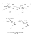
- FIG. 4 (a) shows the first octant in which a point (x + 1, y+1) or (x + 1, y) can be selected as the next point to the current point (x, y)
- FIG. 4 (b) shows the second octant in which a point (x + 1, y) or (x+1, y-1) can be selected as the next point
- FIG. 4 (c) shows the third octant in which a point - (x+1, y-1) or (x, y-1) can be selected as the next, point
- FIG. 4 (a) shows the first octant in which a point (x + 1, y+1) or (x + 1, y) can be selected as the next point to the current point (x, y)
- FIG. 4 (b) shows the second octant in which a point (x + 1, y) or (x+1, y-1) can be selected as the next point
- FIG. 4 (c) shows the third octant in which
- FIG. 4 (d) shows the fourth octant in which a point (x, y-1) or (x-1, y-1) can be selected as the next point
- FIG. 4 (e) shows the fifth octant in which a point (x-1, y-1) or (x-1, y) can be selected as the next point
- FIG. 4 (f) shows the sixth octant in which a point (x-1, y) or (x-1, y + 1) can be selected as the next point
- FIG. 4 (g) shows the seventh octant in which a point (x-1, y + 1) or (x, y + 1) can be selected as the next point
- FIG. 4 (h) shows the eighth octant in which a point (x, y + 1) or (x + 1, y + 1) can be selected as the next point.
- a and ⁇ are:
- a changes while ⁇ does not, in a transistion between the first and second octants, or between the third and fourth octants, or the fifth and sixth, or the seventh and eighth octants.
- ⁇ changes but a does not, in any transition between the second and third, or the fourth and fifth, the sixth and seventh, or the eigth and first octants.
- a and ⁇ will change in value and must be updated.
- T1 is a parameter which must be added to ⁇ after selecting a point that displaces by (+1 or (-1) along either X or Y direction from the current point (x, y).
- T1 has the following values:
- T1 is 2a in the first, second, fifth and sixth octant, and is 2c in the third, fourth, seventh and eighth octants.
- T2 is a parameter which must be added to a after selecting a point that displaces by (+1) or (-1) along either X or Y direction from the current point (x, y), and must be added to ⁇ after selecting a point that displaces by (+1) or (-1) in X direction and by (+1) and (-1) in Y direction, from the current point (x, y).
- T2 has the following values:
- T3 is 2a + 2c + 2b in the first, fourth, fifth and eighth octants and is 2a + 2c -2b in the second, third, sixth and seventh octants.
- Table 1 shows the values of ⁇ , ⁇ , T1 (T1'), T2 and T3 (T3') in the eight octants.
- the equations in the change column are:
- the start point (X s , Y s ) is to be given.
- values for F, a, ⁇ , T1, T1' and b are obtained at the start point and an octant is selected.
- an octant is selected. For example, when drawing a circle if it is assumed that the start point is (-5, 5) and the initial octant is the first octant, then (by Table 1) are set.
- values for T3, T3' and T2 are found from the following equations (by Table 1):
- the current octant is the first or fifth octant, or not, in block 12. If so, as shown in the block 14, an operation is performed to change the value of a. This means that the current octant is changed to the second or the sixth octants, respectively. In the above example, this changes the first octant to the second octant. If in the block 12 it is decided that the current octant is not the first or the fifth octant, it is the third or the seventh octant, so that an operation is performed in the block 16 to change the value of a. This means that the current octant is changed to the fourth or the eighth octant.
- the block 10 provides an affirmative result of judgment, the necessity of change of ⁇ is detected, and then, as shown in the block 18, it is judged whether the current octant is the second or sixth octant, or not. If so, as shown in the block 20, an operation is performed to change ⁇ . This means that the current octant is changed to the third or the seventh octant. If the block 18 provides a negative decision, the current octant is the fourth or the eighth octant, so that an operation is performed to change ⁇ , as showh in block 22. This means that the current octant is changed to the fifth or the first octant.
- T1 (T1').. T2 and T3(T3') are also changed according to Table 1, as briefly indicated in block 24 of FIG. 1. It is clear from Table 1 that new values for all of them corresponding to the new octant can be determined using the values set in the block 2 or 4.
- the signs of the new a and ⁇ are checked, again in the decision block 6. If a and ⁇ have different signs, the point selection process in block 30 is performed. If they still have the same sign, the octant change process in block 8 is again performed. This process continues until a and ⁇ have different signs.
- F and a have different signs, it is first judged in the block 32 whether F and a have the same or different signs. It is equivalent to the checking of signs of F and ß because, when it is intended to draw a curve in the region of F a 0, F is positive (including zero), so that the fact that F and a have the same sign means that a is positive (or zero) and ⁇ is negative. When it is intended to draw a curve in the region of F ⁇ 0, F is negative, so the fact that F and a have the same sign means that a is negative and is positive (or zero).
- the signs of F and F + ⁇ are compared, as shown in block 34. If the same sign, the point that displaces by (+1) or (-1) along either X or Y direction is selected, as shown in the block 36. Thus, if it is assumed to be the first octant, (X+1, Y) is selected. If F and F + ⁇ are judged in block 34 to have different signs, the point that displaces by (+1) or (-1) in the X direction and (+1) or (-1) in the Y direction is selected, as shown in the block 42. Now, if it is assumed to be the first octant, - (X+1, Y+1) is selected.
- F and a are judged in block 32 to have different signs, the signs of F and F + a are compared in the block 40. If the same sign, the point that displaces by (+ 1) or (-1) in the X direction and (+1) or (-1) in the Y direction is selected as shown in the block 42. If F and F + a are judged to have different signs, the point that displaces by (+ 1) or (-1) along either X or Y direction is selected, as shown in the block 36.
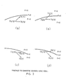
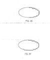
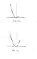
- Tables 3 and 4 below, taken together as one table, show F, ⁇ , ⁇ and the octant change when drawing the curve of FIG. 6, also recalling Table 2 above.
- Table 5 shows F, ⁇ , ⁇ and the octant change when drawing the curve of FIG. 7, while also recalling Table 2 above.
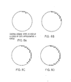
- Table 6A, 6B, 6C, 6D, 6E, 6F, 6G and 6H show F, ⁇ , ⁇ , the octant, T1, T1', T2, T3 and T3' corresponding to FIGS. 8A to 8H, respectively.
- Table 7A, 7B, 7C, 7D, 7E and 7F show F, a, ⁇ , the octant, T1, T1', T2. T3 and T3' corresponding to FIGS. 9A to 9F, respectively.
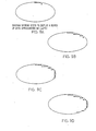
- Table 8A, 8B, 8C, 8D, 8E and 8F show F, a, ⁇ , the octant, T1, T1', T2, T3 and T3' corresponding to FIGS. 10A to 10F, respectively.
- Table 9A, 9B, 9C, 9D, 9E, 9F and 9G show F, a, ⁇ , the octant, T1, T1', T2, T3 and T3' corresponding to FIGS. 11 A to 11G, respectively.
- FIG. 12 shows a configuration of an apparatus used for implementing the method of FIG. 1.
- the parameters F, a, S, T1, T1' and b representing a curve to be drawn as well as the octant are given through a data bus 50 and a multiplexer 52.
- the parameters F, a, ⁇ , T1, T1' and b are stored in an F register 60, a register 54, ⁇ register 56, T1 register 62, T1' register 64 and b register 58, respectively.
- the octant is provided to an octant section 74.
- a pair of start coordinates (X s , Y s ) is set in an X counter 84 and a Y counter 86, respectively.
- an adder control circuit 78 receives an instruction to perform operation according to the following equations through the data bus 50 and the multiplexer 52:
- an adder 80 performs the above operations using output from the T1, T1' and b registers 62, 64 and 58, respectively, and supplies the results to T3, T3' and T2 registers 68, 70 and 66, respectively.
- a first sign judging section 72 receives outputs from the a and ⁇ registers 54 and 56 and compares the signs of a and ⁇ .
- the first sign judging section 72 supplies an octant change request signal to the octant section 74 through a line 73 if the signs of a and ⁇ are the same.
- the octant section 74 also receives through a line 75 a signal indicating whether change of a was performed in the last octant change or not. However, it is unknown whether a was changed in the last octant change when the octant is first provided. So a signal indicating whether change of a should be assumed in the last octant change or not is supplied at the same time when an octant is provided from outside.
- the octant section 74 When the octant section 74 receives a signal indicating that a change of a was (or would have been) performed in an octant preceding to the given octant, it causes the adder 80 to perform an operation through the adder control circuit 78 if the given octant is the second, third, sixth or seventh octant, and supplies the result to the register 56.
- the octant section 74 causes the adder 80 to perform an operation through the adder control circuit 78 if the given octant is the first fourth, fifth or eighth octant, and supplies the result to the ⁇ register 56.
- the first sign judging section 72 does not issue the octant change request signal any more. Then, the second sign judging section 76 receives the outputs of the a register 54 and the - F register 60 and checks the signs of F and ⁇ . If they are the same, the section 76 instructs the adder control circuit 78 to perform an operation to generate F + ⁇ . According to this, the adder 80 receives the outputs of the F and ⁇ registers 60 and 56, performs the operation (F + ⁇ ), and supplies the result to a step control circuit 82, through the miltiplexer 52.
- the step control circuit 82 is also supplied with the output of the F register 60, and a signal representing the current octant from the octant section 74.
- the step control circuit 82 generates output as listed in Table 10 below.
- the second sign judging circuit 76 detects that the signs of F and a are different, it instructs the adder control circuit 78 to perform an operation to generate F + ⁇ .
- the adder 80 receives the outputs of the F and a registers 60 and 54, performs the operation (F + a), and supplies the result to the step control circuit 82.In this case, the step control circuit 82 generates output as listed in Table 11.
- the X and Y counters 84 and 86 respectively, increase or decrease the values of X and Y by one according to output supplied from the step control circuit 82.
- the output of the step control circuit 82 is also supplied to the adder control circuit 78.
- the adder control circuit 78 causes the adder 80 to perform the following operations to update the values of F, a and ⁇ .
- the adder control circuit 78 causes the adder 80 to perform the following operations to update the values of F,
- the change of octant can be continuously performed until the signs of ⁇ and become different, and, therefore, a sharp curve in which a plurality of octant changes are continuously occurring can easily be drawn.
Landscapes
- Engineering & Computer Science (AREA)
- Physics & Mathematics (AREA)
- Computer Hardware Design (AREA)
- General Physics & Mathematics (AREA)
- Theoretical Computer Science (AREA)
- Radar, Positioning & Navigation (AREA)
- Remote Sensing (AREA)
- Image Generation (AREA)
- Controls And Circuits For Display Device (AREA)
- Digital Computer Display Output (AREA)
- Complex Calculations (AREA)
Applications Claiming Priority (2)
| Application Number | Priority Date | Filing Date | Title |
|---|---|---|---|
| JP60100672A JPS61261779A (ja) | 1985-05-14 | 1985-05-14 | 二次曲線信号発生装置 |
| JP100672/85 | 1985-05-14 |
Publications (2)
| Publication Number | Publication Date |
|---|---|
| EP0201754A2 true EP0201754A2 (de) | 1986-11-20 |
| EP0201754A3 EP0201754A3 (de) | 1990-07-25 |
Family
ID=14280252
Family Applications (1)
| Application Number | Title | Priority Date | Filing Date |
|---|---|---|---|
| EP86105380A Ceased EP0201754A3 (de) | 1985-05-14 | 1986-04-18 | Verfahren zum Generieren von quadratischen Kurvensignalen |
Country Status (3)
| Country | Link |
|---|---|
| US (1) | US4789954A (de) |
| EP (1) | EP0201754A3 (de) |
| JP (1) | JPS61261779A (de) |
Cited By (3)
| Publication number | Priority date | Publication date | Assignee | Title |
|---|---|---|---|---|
| WO1989006031A3 (en) * | 1987-12-18 | 1989-07-13 | Digital Equipment Corp | Method of drawing in graphics rendering system |
| US4935880A (en) * | 1987-12-24 | 1990-06-19 | Digital Equipment Corporation | Method of tiling a figure in graphics rendering system |
| FR2646257A1 (fr) * | 1989-04-24 | 1990-10-26 | Digital Equipment Int | Procede d'affichage d'arcs de courbes parametriques polynomiales, sur un support de visualisation d'un moyen d'affichage relie a un ordinateur |
Families Citing this family (6)
| Publication number | Priority date | Publication date | Assignee | Title |
|---|---|---|---|---|
| JPS63186385A (ja) * | 1987-01-28 | 1988-08-01 | Mita Ind Co Ltd | だ円パタ−ン発生装置 |
| US5313227A (en) * | 1988-04-15 | 1994-05-17 | International Business Machines Corporation | Graphic display system capable of cutting out partial images |
| US4941116A (en) * | 1988-07-15 | 1990-07-10 | Honeywell Inc. | Elliptical arc generator for display systems |
| US5495160A (en) * | 1993-12-06 | 1996-02-27 | Reliance Electric Company | Digital sine wave generator and motor controller |
| US5739818A (en) * | 1995-05-31 | 1998-04-14 | Canon Kabushiki Kaisha | Apparatus and method for performing perspectively correct interpolation in computer graphics |
| JP7172420B2 (ja) * | 2018-10-15 | 2022-11-16 | 株式会社ニューフレアテクノロジー | 描画データ生成方法及びマルチ荷電粒子ビーム描画装置 |
Family Cites Families (5)
| Publication number | Priority date | Publication date | Assignee | Title |
|---|---|---|---|---|
| US3917932A (en) * | 1970-03-24 | 1975-11-04 | Yaskawa Denki Seisakusho Kk | Generation of digital functions |
| JPS5386122A (en) * | 1977-01-07 | 1978-07-29 | Nippon Telegr & Teleph Corp <Ntt> | Pattern signal generator |
| US4272808A (en) * | 1979-05-21 | 1981-06-09 | Sperry Corporation | Digital graphics generation system |
| US4484298A (en) * | 1981-04-30 | 1984-11-20 | Yokogawa Hokushin Electric Corporation | Method and device for generation of quadratic curve signal |
| US4692887A (en) * | 1983-05-10 | 1987-09-08 | Casio Computer Co., Ltd. | Circle and circular arc generator |
-
1985
- 1985-05-14 JP JP60100672A patent/JPS61261779A/ja active Granted
-
1986
- 1986-04-18 EP EP86105380A patent/EP0201754A3/de not_active Ceased
- 1986-05-13 US US06/862,901 patent/US4789954A/en not_active Expired - Fee Related
Cited By (3)
| Publication number | Priority date | Publication date | Assignee | Title |
|---|---|---|---|---|
| WO1989006031A3 (en) * | 1987-12-18 | 1989-07-13 | Digital Equipment Corp | Method of drawing in graphics rendering system |
| US4935880A (en) * | 1987-12-24 | 1990-06-19 | Digital Equipment Corporation | Method of tiling a figure in graphics rendering system |
| FR2646257A1 (fr) * | 1989-04-24 | 1990-10-26 | Digital Equipment Int | Procede d'affichage d'arcs de courbes parametriques polynomiales, sur un support de visualisation d'un moyen d'affichage relie a un ordinateur |
Also Published As
| Publication number | Publication date |
|---|---|
| US4789954A (en) | 1988-12-06 |
| JPS61261779A (ja) | 1986-11-19 |
| EP0201754A3 (de) | 1990-07-25 |
| JPH0523439B2 (de) | 1993-04-02 |
Similar Documents
| Publication | Publication Date | Title |
|---|---|---|
| US5363479A (en) | System and method for rendering bezier splines | |
| Miyazaki et al. | An improved pattern matching algorithm for strings in terms of straight-line programs | |
| EP0218984A2 (de) | Rechnergraphikverarbeitungsgerät und -verfahren | |
| EP0336776A2 (de) | Bildvergrösserung | |
| EP0201754A2 (de) | Verfahren zum Generieren von quadratischen Kurvensignalen | |
| US4593372A (en) | Line generating method | |
| US6052489A (en) | Image output apparatus and method | |
| US4608660A (en) | Data processing system with condition data setting function | |
| US6668020B2 (en) | Method for motion estimation in video coding | |
| US5079719A (en) | Method and apparatus for clipping polygons | |
| EP0388089B1 (de) | Bildverarbeitungsgerät | |
| US4849907A (en) | Draw processing method and apparatus | |
| JPH0721224A (ja) | 図形修正方法 | |
| US6914602B2 (en) | Approximating gradients with offset midpoints | |
| EP1315126A2 (de) | Bildverarbeitungsverfahren und -vorrichtung, Bildausgabe-Anlage und Speichermedium | |
| US5809170A (en) | Method for automatically recognizing line symmetry of a figure | |
| JPH05242238A (ja) | 所与の拡大率によって画像を拡大する方法及び装置 | |
| EP0471849A1 (de) | Verfahren zur erzeugung von punktsignalen für zeichenmuster und einrichtung hierzu | |
| Čepek et al. | Note: On the two‐machine no‐idle flowshop problem | |
| JPS63292375A (ja) | 階層化構造的テンプレ−ト・マッチング方法 | |
| US6654774B1 (en) | Generation of sign extended shifted numerical values | |
| EP0637000A2 (de) | Geradlinigkoordinatengenerator | |
| EP0707286A2 (de) | Verfahren und Gerät zum Füllen von Polygonen auf einem Rechnerbildschirm | |
| JP2780496B2 (ja) | 描画装置のクリッピング処理方式 | |
| JP2507812B2 (ja) | 平方根計算方法 |
Legal Events
| Date | Code | Title | Description |
|---|---|---|---|
| PUAI | Public reference made under article 153(3) epc to a published international application that has entered the european phase |
Free format text: ORIGINAL CODE: 0009012 |
|
| AK | Designated contracting states |
Kind code of ref document: A2 Designated state(s): DE FR GB |
|
| 17P | Request for examination filed |
Effective date: 19870327 |
|
| PUAL | Search report despatched |
Free format text: ORIGINAL CODE: 0009013 |
|
| AK | Designated contracting states |
Kind code of ref document: A3 Designated state(s): DE FR GB |
|
| 17Q | First examination report despatched |
Effective date: 19920115 |
|
| STAA | Information on the status of an ep patent application or granted ep patent |
Free format text: STATUS: THE APPLICATION HAS BEEN REFUSED |
|
| 18R | Application refused |
Effective date: 19930215 |
|
| RIN1 | Information on inventor provided before grant (corrected) |
Inventor name: MORIMOTO, YUTAKA Inventor name: IIDA, HIDEAKI Inventor name: MAMIYA, JOHJI |