EP0200979A2 - Tube bending machine - Google Patents
Tube bending machine Download PDFInfo
- Publication number
- EP0200979A2 EP0200979A2 EP86105500A EP86105500A EP0200979A2 EP 0200979 A2 EP0200979 A2 EP 0200979A2 EP 86105500 A EP86105500 A EP 86105500A EP 86105500 A EP86105500 A EP 86105500A EP 0200979 A2 EP0200979 A2 EP 0200979A2
- Authority
- EP
- European Patent Office
- Prior art keywords
- clamping
- bending
- clamping jaw
- bending template
- template
- Prior art date
- Legal status (The legal status is an assumption and is not a legal conclusion. Google has not performed a legal analysis and makes no representation as to the accuracy of the status listed.)
- Granted
Links
Images

Classifications
-
- B—PERFORMING OPERATIONS; TRANSPORTING
- B21—MECHANICAL METAL-WORKING WITHOUT ESSENTIALLY REMOVING MATERIAL; PUNCHING METAL
- B21D—WORKING OR PROCESSING OF SHEET METAL OR METAL TUBES, RODS OR PROFILES WITHOUT ESSENTIALLY REMOVING MATERIAL; PUNCHING METAL
- B21D7/00—Bending rods, profiles, or tubes
- B21D7/02—Bending rods, profiles, or tubes over a stationary forming member; by use of a swinging forming member or abutment
- B21D7/024—Bending rods, profiles, or tubes over a stationary forming member; by use of a swinging forming member or abutment by a swinging forming member
-
- B—PERFORMING OPERATIONS; TRANSPORTING
- B21—MECHANICAL METAL-WORKING WITHOUT ESSENTIALLY REMOVING MATERIAL; PUNCHING METAL
- B21D—WORKING OR PROCESSING OF SHEET METAL OR METAL TUBES, RODS OR PROFILES WITHOUT ESSENTIALLY REMOVING MATERIAL; PUNCHING METAL
- B21D7/00—Bending rods, profiles, or tubes
- B21D7/02—Bending rods, profiles, or tubes over a stationary forming member; by use of a swinging forming member or abutment
- B21D7/021—Construction of forming members having more than one groove
Definitions
- the invention relates to a pipe bending machine with the features of the preamble of claim 1.
- a contact surface in particular a recess for exchangeably accommodating a clamping body provided with the clamping surface, is provided on the bending template and the clamping jaw, and each clamping body is arranged on a guide and provided with a hydraulic drive, which moves the clamping body with a vertical movement in the recess so that one or the other clamping surface of the plurality of different clamping surfaces of the clamping body arranged one above the other enters the plane of the groove of the bending template.
- the present invention is based on the task of arranging and moving the clamping bodies on the bending template and on the clamping jaw in such a way that their rapid change is possible and the clamping surfaces that are not in operation when the tube is inserted into the tube bending machine or during bending to disturb.
- the proposal to arrange the cylinder space for the drive of the clamping body of the bending template within the bending template and to arrange the cylinder space for the clamping body of the clamping jaw within the clamping jaw means that the hydraulic drive protrudes only a small amount above the top of the bending template or clamping jaw and therefore no or only insignificant hindrance can occur when inserting the tube or when bending.
- the clamping bodies are connected to the associated piston rod via a cantilever.
- the bending template is comparatively flat, then part of the cylinder can protrude above the top. It is also possible for a part of the cylinder to protrude downward over the underside of the bending template into the bending table. In any case, the invention provides that the overall height of the bending template and / or the clamping jaw is used to accommodate or partially accommodate the hydraulic cylinder.
- the clamping jaw can be rotated in a manner known per se about a horizontal axis and has two flat surfaces which are adjacent to one another, preferably at a right angle, and on one of the two surfaces or on both surfaces of the clamping body provided with several different clamping surfaces is slidably mounted. This measure makes it possible in a simple manner to arrange clamping surfaces of different designs in a comparatively narrow space and to bring them into effect quickly.
- Another proposal is that there are three different clamping surfaces on top of one another on the clamping body arranged on the bending template and two different clamping surfaces arranged one behind the other and one above the other in the working position on the clamping jaw assigned to the clamping jaw.
- FIG. 1 shows a conventional pipe bending machine with a feed carriage 10, which can slide back and forth on one or more guide rails 11 on the top of the machine housing 12.
- the feed carriage 10 has a hollow cylinder 13, in the interior of which there is a clamping sleeve 14, in which the end region of the pipe section or pipe 15 to be bent is clamped.
- the pipe section 15 is guided around a pivotably mounted bending template 16, which has a groove 17 for the pipe which corresponds to the pipe radius.
- a clamping jaw 19 is pressed by means of a clamping device 18, which also has a groove corresponding to the pipe radius as clamping surface and clamps the pipe 15 on the bending template 16.
- a hydraulic cylinder 20 is shown as an example, which moves the clamping device 18 of the clamping jaw 19 towards the bending template 16 for clamping the tube or removes it from this template.
- the bending template 16 is fixedly arranged on the bending table 21, while the clamping device 18 can be pushed back and forth in the indicated arrow direction 22 via the cylinder 20 shown as an example. If the bending template 16 is pivoted over the bending table 21 together with the clamping jaw 19 in the direction of the arrow 23, the pipe section 15 is given a curvature which corresponds to the profile of the bending template 16. During this bending process, the end part of the pipe section 15 remains clamped in the clamping sleeve 14 of the feed carriage 10 in order to safely guide the pipe section in all positions.
- a slide rail 24 is pressed onto this pipe section part, which also has a groove which corresponds to the pipe radius.
- the clamping sleeve 14 of the feed carriage 10 not only clamps the pipe section 15 firmly, but also turns it by amounts up to 360 ° if successive pipe bends are to be bent in different directions.
- a hydraulic motor rotates a worm which interacts with a worm wheel (not shown) which is connected to the clamping sleeve 14.
- FIG. 2 shows an exhaust pipe which can be produced with the bending machine and in which curved sections or pipe bends S 1 and S 2 as well as S 3 and S 4 are directly connected. There are also linear intermediate lengths L 1, L 2 and L 3, which, however, do not need to be present except for the length L 1.
- FIG. 2 thus shows a tube in which there are partially straight intermediate lengths between bends and partially straight intermediate lengths between bends do not exist.
- This tube shown in Figure 2 can be bent with a single relaxation on the tube bending machine. Such a machine is shown as an example in FIG. 3.
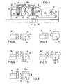
- FIG. 3 shows that the cylinder space or cylinder 25 of the hydraulic drive, which has a piston 26 with a piston rod 27, is arranged within the bending template.
- a right-angled outrigger 28 At the upper end of the piston rod there is a right-angled outrigger 28, on which a clamping element 30 is arranged via a fastening element 29, which has differently designed clamping surfaces 31 and 32 at two different heights.
- the bending template has the bending groove 33.
- the opposing clamping jaw 19 also has a cylinder 25a with a piston and piston rod of the design described above, so that the clamping body 30a with the associated clamping surfaces 31a and 32a arranged one above the other can be used in different operating positions.
- the jaw body 19 is additionally rotatable about the horizontal axis 34, specifically via a hydraulic motor 35 which is provided with a boom 36 which is articulated on a rod 37 which is fastened to the axis 38 of the clamping jaw 19 .
- the clamping jaw has two flat surfaces 39 and 40 adjacent at a right angle, the clamping body 30a with the different clamping surfaces 31a and 32a being slidably mounted on the surface 40, while a stationary clamping body 41 is arranged on the surface 39.
- Figures 4 to 8 show different positions of the clamping body 30 to the opposite clamping body 30a or depending on the rotation of the clamping jaw to the opposite individual clamping body 41.
- Figure 8 shows that a clamping body 30 is arranged on the bending template 16, which has three clamping surfaces arranged one above the other of different dimensions or design.
- Clamping bodies 30a and 41a are present on the clamping jaw 19, which can be displaced on the assigned surfaces via a hydraulic drive and each have two different clamping surfaces.
Landscapes
- Engineering & Computer Science (AREA)
- Mechanical Engineering (AREA)
- Bending Of Plates, Rods, And Pipes (AREA)
Abstract
Bei der Rohrbiegemaschine mit einem an einer Achse schwenkbaren Biegetisch, der eine Biegeschablone und eine gegenüber dieser verschiebbare Spannbacke aufweist und wobei Biegeschablone und Spannbacke geraden und gekrümmten Abschnitten des zu biegenden Rohres angepaßte, jeweils einander zugeordnete Klemmflächen an Klemmkörpern aufweisen, die durch eine hydraulische Kolben-Zylinder-Anordnung bewegt sind, ist der jeweilige hydraulische Zylinder (25, 25a) des Antriebes der Klemmkörper (30, 30a) in der Biegeschablone (16) und/oder in der Spannbacke (19) angeordnet.
Description
Die Erfindung betrifft eine Rohrbiegemaschine mit den Merkmalen des Oberbegriffes des Anspruches 1.The invention relates to a pipe bending machine with the features of the preamble of claim 1.
Beim Biegen von Rohren, bei denen sich ohne gerade Zwischenlängen ein gebogener Abschnitt an den nächsten gebogenen Abschnitt anfügt oder bei Rohren, die an ihrem Kopfende eine andere Ausbildung haben als über ihre Länge, so beispielsweise durch eine Aufweitung oder einen vor dem Biegen abgeschweißten Flansch, ist ein Wechsel der Klemmflächen an der Biegeschablone und auch an der Spannback notwendig. Es sind viele Vorschläge unterbreitet worden, diesen Wechsel der Klemmflächen vorzunehmen.When bending pipes in which a curved section joins the next bent section without straight intermediate lengths or in pipes which have a design at their head end that is different from their length, for example by an expansion or a flange welded before bending, it is necessary to change the clamping surfaces on the bending template and also on the clamping jaw. Many suggestions have been made to make this change of the clamping surfaces.
In der deutschen Patentschrift 26 26 202 des Anmelders ist vorgeschlagen worden, die Spannbacke um eine horizontale Achse drehbar anzuordnen, damit an deren Umfang angeordnete Klemmflächen unterschiedlicher Ausbildung zur Wirkung kommen können.In the applicant's
In der europäischen Patentanmeldung 0120336 des Anmelders ist vorgeschlagen worden, daß jeweils an der Biegeschablone und der Spannbacke eine Anlagefläche, insbesondere Ausnehmung zur auswechselbaren Aufnahme eines mit der Klemmfläche versehenen Klemmkörpers vorhanden ist und jeder Klemmkörper an einer Führung angeordnet und mit einem hydraulischen Antrieb versehen ist, der den Klemmkörper mit einer Vertikalbewegung in der Ausnehmung so bewegt, daß von den mehreren übereinander angeordneten unterschiedlichen Klemmflächen des Klemmkörpers die eine oder andere Klemmfläche in die Ebene der Rille der Biegeschablone gelangt.In the applicant's European patent application 0120336 it has been proposed that a contact surface, in particular a recess for exchangeably accommodating a clamping body provided with the clamping surface, is provided on the bending template and the clamping jaw, and each clamping body is arranged on a guide and provided with a hydraulic drive, which moves the clamping body with a vertical movement in the recess so that one or the other clamping surface of the plurality of different clamping surfaces of the clamping body arranged one above the other enters the plane of the groove of the bending template.
Die vorliegende Erfindung geht von der Aufgabe aus, die Klemmkörper an der Biegeschablone und an der Spannbacke in der Weise anzuordnen und zu bewegen, daß deren schneller Wechsel möglich und die nich in Tätigkeit befindlichen Klemmflächen beim Einlegen des Rohres in die Rohrbiegemaschine oder während des Biegens nicht stören.The present invention is based on the task of arranging and moving the clamping bodies on the bending template and on the clamping jaw in such a way that their rapid change is possible and the clamping surfaces that are not in operation when the tube is inserted into the tube bending machine or during bending to disturb.
Zur Lösung dieser Aufgabe wird bei einer Rohrbiegemaschine mit den Merkmalen nach dem Oberbegriff des Anspruches 1 vorgeschlagen, daß der hydraulische Zylinder des Klemmkörper-Antriebes in der Biegeschablone oder in der Spannbacke angeordnet ist.To solve this problem it is proposed in a pipe bending machine with the features according to the preamble of claim 1, that the hydraulic cylinder of the clamping body drive is arranged in the bending template or in the clamping jaw.
Durch den Vorschlag, innerhalb der Biegeschablone den Zylinderraum für den Antrieb des Klemmkörpers der Biegeschablone anzuordnen und innerhalb der Spannbacke den Zylinderraum für den Klemmkörper der Spannbacke anzuordnen, wird erreicht, daß der hydraulische Antrieb nur um ein geringes Maß über die Oberseite der Biegeschablone oder Spannbacke vorsteht und daher beim Einlegen des Rohres oder beim Biegen keine oder nur unwesentliche Behinderung erfolgen kann. Bei dieser Lösung sind die Klemmkörper über einen Ausleger mit der zugeordneten Kolbenstange verbunden.The proposal to arrange the cylinder space for the drive of the clamping body of the bending template within the bending template and to arrange the cylinder space for the clamping body of the clamping jaw within the clamping jaw means that the hydraulic drive protrudes only a small amount above the top of the bending template or clamping jaw and therefore no or only insignificant hindrance can occur when inserting the tube or when bending. In this solution, the clamping bodies are connected to the associated piston rod via a cantilever.
Sofern die Biegeschablone vergleichsweise flach ist, dann kann ein Teil des Zylinders über die Oberseite hinaus nach oben ragen. Es ist auch möglich, daß ein Teil des Zylinders nach unten über die Unterseite der Biegeschablone in den Biegetisch hineinragt. Jedenfalls sieht die Erfindung vor, daß die Bauhöhe der Biegeschablone und/oder der Spannbacke zur Unterbringung oder teilweisen Unterbringung des Hydraulik-Zylinders genutzt wird.If the bending template is comparatively flat, then part of the cylinder can protrude above the top. It is also possible for a part of the cylinder to protrude downward over the underside of the bending template into the bending table. In any case, the invention provides that the overall height of the bending template and / or the clamping jaw is used to accommodate or partially accommodate the hydraulic cylinder.
In weiterer erfindungsgemäßer Ausgestaltung wird vorgeschlagen, daß die Spannbacke in an sich bekannter Weise um eine horizontale Achse drehbar ist und zwei einander, vorzugsweise in einem rechten Winkel angrenzende ebene Flächen hat und an einer der beiden Flächen oder an beiden Flächen der mit mehreren unterschiedlichen Klemmflächen versehene Klemmkörper verschiebbar gelagert ist. Durch diese Maßnahme ergibt sich auf einfache Weise die Möglichkeit, auf vergleichsweise engem Raum Klemmflächen unterschiedlicher Ausbildung anzuordnen und schnell zur Wirkung zu bringen.In a further embodiment according to the invention it is proposed that the clamping jaw can be rotated in a manner known per se about a horizontal axis and has two flat surfaces which are adjacent to one another, preferably at a right angle, and on one of the two surfaces or on both surfaces of the clamping body provided with several different clamping surfaces is slidably mounted. This measure makes it possible in a simple manner to arrange clamping surfaces of different designs in a comparatively narrow space and to bring them into effect quickly.
Ein weiterer Vorschlag geht dahin, daß an dem der Biegeschablone angeordneten Klemmkörper übereinander drei unterschiedliche Klemmflächen und an dem der Spannbacke zugeordneten Klemmbacke zwei hintereinander und in der Arbeitsstellung übereinander angeordnete unterschiedliche Klemmflächen vorhanden sind.Another proposal is that there are three different clamping surfaces on top of one another on the clamping body arranged on the bending template and two different clamping surfaces arranged one behind the other and one above the other in the working position on the clamping jaw assigned to the clamping jaw.
Die Erfindung ist in der Zeichnung beispielhaft dargestellt.The invention is illustrated by way of example in the drawing.
Es zeigen:
- Figur 1 eine Rohrbiegemaschine in perspektivischer Darstellung,
- Figur 2 ein gebogenes Rohr,
- Figur 3 in teilweise vertikalem Schnitt den Biegetisch mit Biegeschablone und Spannbacke,
- Figur 4 unterschiedlich zueinander angeordnete Klemmflächen, bis 7
- Figur 8 eine abgewandelte Ausbildung der Klemmkörper.
- FIG. 1 shows a pipe bending machine in perspective,
- FIG. 2 shows a bent tube,
- FIG. 3 shows the bending table with a bending template and clamping jaw in a partially vertical section,
- FIG. 4 differently arranged clamping surfaces up to 7
- Figure 8 shows a modified design of the clamping body.
Figur 1 zeigt eine herkömmliche Rohrbiegemaschine mit einem Vorschubwagen 10, der auf einer oder mehreren Führungsschienen 11 auf der Oberseite des Maschinengehäuses 12 hin- und hergleiten kann.FIG. 1 shows a conventional pipe bending machine with a
Der Vorschubwagen 10 hat einen Hohlzylinder 13, in dessen Inneren sich eine Spannhülse 14 befindet, in welcher der Endbereich des zu biegenden Rohrstückes bzw. Rohres 15 eingespannt ist. Das Rohrstück 15 ist um eine schwenkbar gelagerte Biegeschablone 16 herumgeführt, welche eine dem Rohrhalbmesser entsprechende Rille 17 für das Rohr hat. An einem Teil des um die Biegeschablone 16 herumgeführten Rohrstückes 15 ist mittels einer Spanneinrichtung 18 eine Spannbacke 19 angedrückt, welcher ebenfalls eine dem Rohrhalbmesser entsprechende Rille als Spannfläche hat und das Rohr 15 an der Biegeschablone 16 festklemmt. Es ist ein Hydraulikzylinder 20 beispielhaft dargestellt, der die Spanneinrichtung 18 der Spannbacke 19 zur Biegeschablone 16 zur Festklemmung des Rohres hin bewegt oder von dieser Schablone entfernt. Die Biegeschablone 16 ist an dem Biegetisch 21 fest angeordnet, während die Spanneinrichtung 18 über den beispielhaft dargestellten Zylinder 20 in angegebener Pfeilrichtung 22 hin- und herverschiebbar ist. Wird die Biegeschablone 16 über den Biegetisch 21 zusammen mit der Spannbacke 19 in Richtung des Pfeiles 23 umgeschwenkt, so erhält das Rohrstück 15 eine Krümmung, welche dem Profil der Biegeschablone 16 entspricht. Während dieses Biegevorganges bleibt der Endteil des Rohrstückes 15 in der Spannhülse 14 des Vorschubwagens 10 eingespannt, um das Rohrstück in allen Lagen sicher zu führen. Damit das zwischen Spannhülse 14 und Biegeschablone 16 freie Rohrstück 15 seitlich nicht abknicken kann, ist an dieses Rohrstückteil eine Gleitschiene 24 angedrückt, die ebenfalls eine Rille hat, welche dem Rohrhalbmesser entspricht. Die Spannhülse 14 des Vorschubwagens 10 spannt das Rohrstück 15 nicht nur fest ein, sondern wendet es auch um Beträge bis zu 360°, wenn aufeinanderfolgende Rohrbiegungen nach verschiedenen Richtungen gekrümmt werden sollen. Zur Verdrehung der Spannhülse 14 dreht ein hydraulischer Motor eine Schnecke, die mit einem nicht dargestellten mit der Spannhülse 14 in Verbindung stehenden Schneckenrad zusammenwirkt.The
Figur 2 zeigt ein Auspuffrohr, das mit der Biegesmaschine herstellbar ist und bei dem sich gebogene Abschnitte bzw. Rohrbögen S 1 und S 2 sowie S 3 und S 4 unmittelbar anschließen. Es sind auch geradlinige Zwischenlängen L 1, L 2 und L 3 vorhanden, die aber bis auf die Länge L 1 nicht vorhanden zu sein brauchen.FIG. 2 shows an exhaust pipe which can be produced with the bending machine and in which curved sections or pipe bends S 1 and S 2 as well as S 3 and S 4 are directly connected. There are also linear intermediate lengths L 1, L 2 and L 3, which, however, do not need to be present except for the length L 1.
Figur 2 zeigt somit ein Rohr, bei dem teils geradlinige Zwischenlängen zwischen Biegungen vorhanden sind und teils geradlinige Zwischenlängen zwischen Biegungen nicht vorhanden sind. Dieses in Figur 2 dargestellte Rohr kann bei einer einzigen Entspannung auf der Rohrbiegemaschine gebogen werden. Eine solche Maschine ist beispielhaft in Figur 3 dargestellt.FIG. 2 thus shows a tube in which there are partially straight intermediate lengths between bends and partially straight intermediate lengths between bends do not exist. This tube shown in Figure 2 can be bent with a single relaxation on the tube bending machine. Such a machine is shown as an example in FIG. 3.
Figur 3 zeigt, daß innerhalb der Biegeschablone der Zylinderraum bzw. eingesetzte Zylinder 25 des hydraulischen Antriebes angeordnet ist, der einen Kolben 26 mit Kolbenstange 27 aufweist. Am oberen Ende der Kolbenstange ist der rechtwinklig abgehende Ausleger 28 vorhanden, an dem über ein Befestigungselement 29 der Klemmkörper 30 angeordnet ist, der in zwei verschiedenen Höhenlagen unterschiedlich ausgebildete Klemmflächen 31 und 32 aufweist. Die Biegeschablone hat die Biegerille 33.FIG. 3 shows that the cylinder space or
Auch die gegenüberliegende Spannbacke 19 hat einen Zylinder 25a mit Kolben und Kolbenstange der vorbeschriebenen Ausbildung, damit der Klemmkörper 30a mit den zugeordneten übereinander angeordneten Klemmflächen 31a und 32a in unterschiedlichen Betriebsstellungen Anwendung finden kann.The
Nach Figur 3 ist der Klemmbackenkörper 19 zusätzlich um die horizontale Achse 34 drehbar, und zwar über einen Hydro-Motor 35, der mit einem Ausleger 36 versehen ist, der an eine Stange 37 angelenkt ist, die an der Achse 38 der Spannbacke 19 befestigt ist. Die Spannbacke hat zwei in einem rechten Winkel angrenzende ebene Flächen 39 und 40, wobei an der Fläche 40 der Klemmkörper 30a mit den unterschiedlichen Klemmflächen 31a und 32a verschiebbar gelagert ist, während an der Fläche 39 ein ortsfester Klemmkörper 41 angeordnet ist.According to Figure 3, the
Die Figuren 4 bis 8 zeigen unterschiedliche Stellungen des Klemmkörpers 30 zum gegenüberliegenden Klemmkörper 30a oder abhängig von der Drehung der Spannbacke zu dem gegenüberliegenden einzelnen Klemmkörper 41.Figures 4 to 8 show different positions of the
Die unterschiedlichen Arbeitsstellungen der Klemmkörper und deren Klemmflächen erfolgen durch Betätigung der hydraulischen zugeordneten Antriebe durch Ein- und Ausfahren der Kolbenstange und durch Drehung der Spannbacke um die Achse 34. Einer besonderen Erläuterung der Figuren 4 bis 7 bedarf es nicht.The different working positions of the clamping bodies and their clamping surfaces take place by actuating the hydraulically assigned drives by retracting and extending the piston rod and by rotating the clamping jaw about the
Figur 8 zeigt, daß an der Biegeschablone 16 ein Klemmkörper 30 angeordnet ist, der drei übereinander angeordnete Klemmflächen unterschiedlicher Bemessung oder Ausbildung hat. An der Spannbacke 19 sind Klemmkörper 30a und 41a vorhanden, die an den zugeordneten Flächen über einen Hydraulik-Antrieb verschiebbar sind und jeweils zwei unterschiedliche Klemmflächen haben.Figure 8 shows that a
Es sei bemerkt, daß analog zu Figur 8 nicht lediglich zwei einander angrenzende Umfangsflächen ebener Ausbildung mit Klemmkörpern versehen sein können, sondern auch drei oder mehrere einander angrenzende Flächen.It should be noted that, analogously to FIG. 8, not only two adjacent peripheral surfaces of flat design can be provided with clamping bodies, but also three or more adjacent surfaces.
Claims (3)
Applications Claiming Priority (2)
| Application Number | Priority Date | Filing Date | Title |
|---|---|---|---|
| DE3516923 | 1985-05-10 | ||
| DE19853516923 DE3516923A1 (en) | 1985-05-10 | 1985-05-10 | PIPE BENDING MACHINE |
Publications (3)
| Publication Number | Publication Date |
|---|---|
| EP0200979A2 true EP0200979A2 (en) | 1986-11-12 |
| EP0200979A3 EP0200979A3 (en) | 1987-01-07 |
| EP0200979B1 EP0200979B1 (en) | 1989-11-15 |
Family
ID=6270419
Family Applications (1)
| Application Number | Title | Priority Date | Filing Date |
|---|---|---|---|
| EP86105500A Expired EP0200979B1 (en) | 1985-05-10 | 1986-04-21 | Tube bending machine |
Country Status (3)
| Country | Link |
|---|---|
| US (1) | US4821549A (en) |
| EP (1) | EP0200979B1 (en) |
| DE (2) | DE3516923A1 (en) |
Cited By (4)
| Publication number | Priority date | Publication date | Assignee | Title |
|---|---|---|---|---|
| EP0245623A3 (en) * | 1986-05-14 | 1990-03-28 | Rigobert Dipl.-Ing. Schwarze | Tube-bending machine |
| EP0364836A3 (en) * | 1988-10-15 | 1990-11-28 | Günther-F. Pulzer | Method of and device for bending bar-shaped work pieces |
| EP2289643A3 (en) * | 2009-08-24 | 2011-10-05 | Tracto-Technik GmbH & CO. KG | Device for bending elongated workpieces |
| US9849494B2 (en) | 2013-11-15 | 2017-12-26 | Textron Innovations Inc. | Automated bender and systems and methods for providing data to operate an automated bender |
Families Citing this family (6)
| Publication number | Priority date | Publication date | Assignee | Title |
|---|---|---|---|---|
| DE4442030A1 (en) * | 1994-11-25 | 1996-05-30 | Sen Bernhard Kreye | Metal strip bending process for rails of doors and windows |
| DE19530805A1 (en) * | 1995-08-22 | 1997-02-27 | Schwarze Rigobert | CNC controlled pipe bending machine |
| DE19630163C1 (en) * | 1996-07-26 | 1997-12-11 | Schmitz & Brill Gmbh & Co Kg | Tool for clamping and bending e.g. steel tube |
| CN101934314B (en) * | 2010-07-19 | 2012-04-04 | 江苏合丰机械制造有限公司 | Pipe bending device capable of bending left and right in pipe bending machine |
| CN109175036A (en) * | 2018-08-28 | 2019-01-11 | 四川凯润电器有限公司 | A kind of heat-exchange tube bending device |
| CN119819768B (en) * | 2025-03-13 | 2025-06-20 | 江苏精达制管有限公司 | Stainless steel pipe processing auxiliary device that bends |
Family Cites Families (11)
| Publication number | Priority date | Publication date | Assignee | Title |
|---|---|---|---|---|
| DE120336C (en) * | ||||
| DE25279C (en) * | W. NUSSBECK in Berlin, Neuer Markt 8 | Beer cooler | ||
| DE1087431B (en) * | 1959-05-29 | 1960-08-18 | Hilgers Maschinen Und App Baua | Automatic push-out device for a pipe bending machine |
| US3299681A (en) * | 1960-03-22 | 1967-01-24 | Baldwin Lima Hamilton Corp | Program controlled tube bender |
| US3147792A (en) * | 1961-09-25 | 1964-09-08 | Charles F Hautau | Tube and bar bending machinery |
| DE2626202C2 (en) * | 1976-06-11 | 1992-10-29 | Rigobert Dipl.-Ing. 5000 Köln Schwarze | Tube bending machine |
| US4238398A (en) * | 1979-10-31 | 1980-12-09 | The Upjohn Company | Antibiotics 7(R)-O-alkylnogalarols |
| DE3033300A1 (en) * | 1980-09-04 | 1982-04-01 | Rigobert Dipl.-Ing. 5000 Köln Schwarze | PIPE BENDING MACHINE |
| US4495788A (en) * | 1982-08-02 | 1985-01-29 | Eaton-Leonard Corporation | Multiple curvature bender |
| EP0120336B2 (en) * | 1983-03-26 | 1991-10-09 | Rigobert Dipl.-Ing. Schwarze | Tube bending machine |
| JPS59178131A (en) * | 1983-03-28 | 1984-10-09 | Suzuki Motor Co Ltd | Bender |
-
1985
- 1985-05-10 DE DE19853516923 patent/DE3516923A1/en not_active Withdrawn
-
1986
- 1986-04-21 DE DE8686105500T patent/DE3666923D1/en not_active Expired
- 1986-04-21 EP EP86105500A patent/EP0200979B1/en not_active Expired
-
1988
- 1988-01-13 US US07/143,617 patent/US4821549A/en not_active Expired - Lifetime
Cited By (7)
| Publication number | Priority date | Publication date | Assignee | Title |
|---|---|---|---|---|
| EP0245623A3 (en) * | 1986-05-14 | 1990-03-28 | Rigobert Dipl.-Ing. Schwarze | Tube-bending machine |
| EP0364836A3 (en) * | 1988-10-15 | 1990-11-28 | Günther-F. Pulzer | Method of and device for bending bar-shaped work pieces |
| EP2289643A3 (en) * | 2009-08-24 | 2011-10-05 | Tracto-Technik GmbH & CO. KG | Device for bending elongated workpieces |
| US9849494B2 (en) | 2013-11-15 | 2017-12-26 | Textron Innovations Inc. | Automated bender and systems and methods for providing data to operate an automated bender |
| EP3068556A4 (en) * | 2013-11-15 | 2018-02-14 | Textron Innovations Inc. | Providing data for operation of automated bender |
| US10406580B2 (en) | 2013-11-15 | 2019-09-10 | Greenlee Tools, Inc. | Automated bender and systems and methods for providing data to operate an automated bender |
| US10792718B2 (en) | 2013-11-15 | 2020-10-06 | Greenlee Tools, Inc. | Follower bar assembly for a bender |
Also Published As
| Publication number | Publication date |
|---|---|
| DE3666923D1 (en) | 1989-12-21 |
| US4821549A (en) | 1989-04-18 |
| DE3516923A1 (en) | 1986-11-13 |
| EP0200979A3 (en) | 1987-01-07 |
| EP0200979B1 (en) | 1989-11-15 |
Similar Documents
| Publication | Publication Date | Title |
|---|---|---|
| DE3601231C2 (en) | ||
| EP0245623B1 (en) | Tube-bending machine | |
| DE3922326C2 (en) | ||
| EP0108193B1 (en) | Pipe-bending machine | |
| DE3785533T2 (en) | TUBE ALIGNMENT DEVICE. | |
| DE3033300C2 (en) | ||
| DE2626202A1 (en) | PIPE BENDING MACHINE | |
| DE4335901A1 (en) | Double-head pipe bending machine | |
| EP0649687B1 (en) | Tube bending machine | |
| EP0200979B1 (en) | Tube bending machine | |
| DE68904694T2 (en) | CLAMPING MECHANISM OF A DEVICE FOR DRILLING OR LOWERING HOLES IN A WORKPIECE. | |
| DE3627502C2 (en) | Pipe bending machine | |
| EP0120336B2 (en) | Tube bending machine | |
| DE3045791C2 (en) | ||
| DE3831378C2 (en) | Stop device for table saws | |
| DE3619677C1 (en) | Device for lifting and lowering the head and foot sections of a bed frame | |
| DE69800606T2 (en) | Bending device | |
| DE2063041C3 (en) | Device for bending bars and the like | |
| DE3625074C2 (en) | ||
| DE3033950C2 (en) | Tube bending machine | |
| DE10229652B4 (en) | Carriage for pipe bending machine | |
| DE2917670C2 (en) | Jack-up platform capable of walking | |
| AT361760B (en) | DEVICE AND METHOD FOR PRODUCING A TENSION BRACKET FOR FASTENING RAILWAY RAILS | |
| DE19607968A1 (en) | Treatment couch | |
| EP0604747A1 (en) | Bending machine |
Legal Events
| Date | Code | Title | Description |
|---|---|---|---|
| PUAI | Public reference made under article 153(3) epc to a published international application that has entered the european phase |
Free format text: ORIGINAL CODE: 0009012 |
|
| AK | Designated contracting states |
Kind code of ref document: A2 Designated state(s): DE FR GB IT SE |
|
| PUAL | Search report despatched |
Free format text: ORIGINAL CODE: 0009013 |
|
| AK | Designated contracting states |
Kind code of ref document: A3 Designated state(s): DE FR GB IT SE |
|
| 17P | Request for examination filed |
Effective date: 19870124 |
|
| 17Q | First examination report despatched |
Effective date: 19880708 |
|
| GRAA | (expected) grant |
Free format text: ORIGINAL CODE: 0009210 |
|
| AK | Designated contracting states |
Kind code of ref document: B1 Designated state(s): DE FR GB IT SE |
|
| ITF | It: translation for a ep patent filed | ||
| GBT | Gb: translation of ep patent filed (gb section 77(6)(a)/1977) | ||
| ET | Fr: translation filed | ||
| REF | Corresponds to: |
Ref document number: 3666923 Country of ref document: DE Date of ref document: 19891221 |
|
| PLBI | Opposition filed |
Free format text: ORIGINAL CODE: 0009260 |
|
| 26 | Opposition filed |
Opponent name: LANG MASCHINENBAU GMBH U. CO. KG Effective date: 19900816 |
|
| ITTA | It: last paid annual fee | ||
| PLBM | Termination of opposition procedure: date of legal effect published |
Free format text: ORIGINAL CODE: 0009276 |
|
| STAA | Information on the status of an ep patent application or granted ep patent |
Free format text: STATUS: OPPOSITION PROCEDURE CLOSED |
|
| 27C | Opposition proceedings terminated |
Effective date: 19910211 |
|
| EAL | Se: european patent in force in sweden |
Ref document number: 86105500.2 |
|
| REG | Reference to a national code |
Ref country code: GB Ref legal event code: IF02 |
|
| PGFP | Annual fee paid to national office [announced via postgrant information from national office to epo] |
Ref country code: GB Payment date: 20050412 Year of fee payment: 20 |
|
| PGFP | Annual fee paid to national office [announced via postgrant information from national office to epo] |
Ref country code: FR Payment date: 20050419 Year of fee payment: 20 |
|
| PGFP | Annual fee paid to national office [announced via postgrant information from national office to epo] |
Ref country code: SE Payment date: 20050422 Year of fee payment: 20 |
|
| PGFP | Annual fee paid to national office [announced via postgrant information from national office to epo] |
Ref country code: IT Payment date: 20050427 Year of fee payment: 20 |
|
| PGFP | Annual fee paid to national office [announced via postgrant information from national office to epo] |
Ref country code: DE Payment date: 20050524 Year of fee payment: 20 |
|
| PG25 | Lapsed in a contracting state [announced via postgrant information from national office to epo] |
Ref country code: GB Free format text: LAPSE BECAUSE OF EXPIRATION OF PROTECTION Effective date: 20060420 |
|
| REG | Reference to a national code |
Ref country code: GB Ref legal event code: PE20 |
|
| EUG | Se: european patent has lapsed |