EP0200927A2 - Cable tray section for laying service conduits or the like - Google Patents
Cable tray section for laying service conduits or the like Download PDFInfo
- Publication number
- EP0200927A2 EP0200927A2 EP86104623A EP86104623A EP0200927A2 EP 0200927 A2 EP0200927 A2 EP 0200927A2 EP 86104623 A EP86104623 A EP 86104623A EP 86104623 A EP86104623 A EP 86104623A EP 0200927 A2 EP0200927 A2 EP 0200927A2
- Authority
- EP
- European Patent Office
- Prior art keywords
- channel
- cable duct
- profile
- walls
- cover
- Prior art date
- Legal status (The legal status is an assumption and is not a legal conclusion. Google has not performed a legal analysis and makes no representation as to the accuracy of the status listed.)
- Granted
Links
Images

Classifications
-
- H—ELECTRICITY
- H02—GENERATION; CONVERSION OR DISTRIBUTION OF ELECTRIC POWER
- H02G—INSTALLATION OF ELECTRIC CABLES OR LINES, OR OF COMBINED OPTICAL AND ELECTRIC CABLES OR LINES
- H02G3/00—Installations of electric cables or lines or protective tubing therefor in or on buildings, equivalent structures or vehicles
- H02G3/02—Details
- H02G3/04—Protective tubing or conduits, e.g. cable ladders or cable troughs
- H02G3/0437—Channels
-
- H—ELECTRICITY
- H02—GENERATION; CONVERSION OR DISTRIBUTION OF ELECTRIC POWER
- H02G—INSTALLATION OF ELECTRIC CABLES OR LINES, OR OF COMBINED OPTICAL AND ELECTRIC CABLES OR LINES
- H02G3/00—Installations of electric cables or lines or protective tubing therefor in or on buildings, equivalent structures or vehicles
- H02G3/02—Details
- H02G3/04—Protective tubing or conduits, e.g. cable ladders or cable troughs
- H02G3/0406—Details thereof
- H02G3/0418—Covers or lids; Their fastenings
Definitions
- the invention relates to a cable duct profile for laying installation lines or the like.
- a U-shaped duct body With a U-shaped duct body, the installation opening formed by the duct walls is closed by a cover, which is attached in particular to the ends of the duct walls on the outside.
- the invention is based on the object of improving a cable duct profile of the type mentioned at the outset in such a way that it can be manufactured with different cross sections, with partial reuse of its components, so that correspondingly larger or smaller quantities of installation lines can be laid inside .
- the channel walls and the bottom of the channel body are detachably connected to one another and can be exchanged for walls and / or floors of different dimensions. It is important for the invention that the channel walls are interchangeable. Duct walls and floors of other dimensions can be used and a cable duct profile with a different cross section can be produced with it.
- the channel walls and the floor are connected via snap-in connections. After loosening the locking connections by means of advantageous swiveling or sliding movements transverse to the longitudinal axis of the profile, the parts can be exchanged. It is conceivable to use sliding connections instead of the latching connections, so that the parts to be assembled are assembled in their longitudinal direction by pushing one into the other.
- such a design of the connection points has several disadvantages, above all the double assembly length required for assembly, but also the movement resistance due to warping of the parts transversely to their longitudinal direction.
- the bottom of the channel body and / or its cover have on their outer edges in the direction of the channel walls abutment strips, which are engaged by hook strips projecting into the channel interior.
- the latching is therefore advantageously carried out at the edges or in the corner region of the profile.
- the hook strips of a snap-in connection of a duct wall have a pressure web, which can be snapped into a snap-in recess when the cooperating hook and abutment strips are caught while overcoming a snap-in bar.
- Such locking connections ensure a secure cohesion of the components to be locked, that is, in particular the floor with walls, but also the cover, the locking connection being designed such that it connects the associated channel wall in the sense of bracing another locking connection or another releasable connection of a channel part is able to preload with another duct part.
- the hook and abutment strips have a ball joint-like cross section.
- the abutment strips of the bottom and the cover as well as the hook strips of the channel walls are each designed identically in their engagement area.
- the locking connections of the floor and the Lids are interchanged or the channel walls are to be arranged rotated by 180 ° in their plane.
- the latching connections of a channel wall are designed differently or if only one latching connection is present on a channel wall, which has a pressure web and thus prestresses the channel wall, this can optionally be used on the cover of the cable channel profile.
- the bottom and the cover of the channel for each snap connection have a snap bar support projecting into the channel interior, each with a snap recess and a snap bar.
- the latching web supports of the floor are connected to one another in a supporting manner with a connecting web, if necessary having actuating openings, and in the floor a longitudinally running fastening slot opening into a fastening groove enclosed by the gutter profile is arranged.
- the channel profile enables the arrangement of an uninterrupted longitudinal fastening slot with which the cable duct profile can be attached to the supporting surface in a stepless manner.
- the base has at least two channel profiles arranged next to one another, between which two abutment strips are arranged which are matched to their latching web supports. Both channel profiles allow the above-described fastening of the cable duct profile.
- the interior of the channel is divided by an intermediate wall, which is detachably connected to the floor via a snap connection. That is for example required to separate high-voltage and low-voltage installation lines.
- the intermediate wall and the channel walls are of identical design, which facilitates the manufacture and storage of intermediate walls.
- the bottom of the duct body has a cross-section of the cover, or the cover has a cross-section of the base if this is required for special purposes.
- the interchangeability of the cover and base is advantageously used in such a way that a cover cross-section instead of a base cross-section is present in the longitudinal direction of the cable duct profile.
- a cover piece could therefore take the place of a base piece, for example if there is no fastening possibility and a simple and therefore cheaper profile is sufficient, or if outlet openings are to be produced with a simple cover profile.
- separate duct wall section is provided to be able to, for example, to slightly expand a threaded through the side outlet openings harness, 'without having to remove the channel wall as a whole.
- this goal is achieved in that the cable duct profile is slotted at intervals over its entire length, so that the individual tabs which are created can be broken out at the desired location.
- slitting is a time-consuming manufacturing process and the slits reduce the duct wall stiffness. Both can be avoided by using the aforementioned duct wall sections.
- the cross-sectional lengths of K are portable channel profile with a grid measured in a ratio of 1: 1 or an integer multiple.
- the cable duct Profile releasably connected to a hollow profile rod, the cross-sectional lengths of which are matched to those of the cable duct and which has at least one fastening duct arranged congruently with the fastening slot of the cable duct for receiving a connecting part.
- the cable duct profile is provided with a support with which it can be freely laid, particularly over longer lengths, in the absence of other fastening options.
- the attachment of the cable duct profile to frames that are constructed from such hollow profile rods is also possible without any problems and facilitates e.g. the production of work tables using such hollow profile bars and cable duct profiles.
- the cable duct profile can also be laid across or at any angle to the hollow profile rod and attached to it.
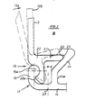
- the cable duct profile 10 of FIG. 1 which is expediently made of a light metal alloy for reasons of strength, has a base 14, two walls 13 attached to it and a cover 12 which enclose the interior 18 of the cable duct profile 10, in which e.g. electrical installation lines are laid.
- the base 14 and the channel walls 13 are assembled with latching connections 15 to form a channel body 11 which has a wide installation opening 18a between the ends 39 of the channel walls 13.
- the channel wall 13 has an L-shaped hook strip 20 which projects into the channel interior 18 and runs parallel to the wall 13 with its long L-leg.
- This L-leg or the hook strip 20 engages behind an abutment strip 19 present on the outer edge 17 of the base 14, which protrudes from the base 14 in the direction of the channel wall 13 and is flush with it.
- the abutment strip 19 has a bead 19a on the wall side, which has a circular cross-section in its area touching the hook strip 20. Accordingly, the hook strip 20 is also circularly profiled in its area of contact with the abutment strip 19.
- the hook strip 20 has at its bottom end a rib 20a projecting towards the abutment bar 19, with which the bead 19a is engaged.
- the cross section of the hook bar 20 and the abutment bar 19 in the contact area of both is ball-joint-like.
- the locking web carrier 24 is designed and arranged such that the pressure web 21 is firmly seated in the locking recess 23 and is held therein.
- the locking web carrier 24 is integrally connected to the bottom 14.
- the locking connection 15 is assembled in such a way that the wall 13 is initially arranged in the dot-dash position in which the hook strip 20 is seated on the bead 19a in such a way that the pressure web 21 abuts the locking web 22. Then the wall 13 is pivoted further in the direction of the arrow 13a and by overcoming the latching web 22 until the wall 13 assumes its position shown with a solid line. This position can be blocked in that an approximately a-strong screw is arranged between the hook bar 20 and the part 24a of the locking web carrier 24, which screw is screwed through a hole made with the aid of a drilling auxiliary groove 37 in the bottom 14. This is the drilling auxiliary groove 37 is arranged in the projection between the hook strip 20 and the locking web carrier 24.
- the dashed position 13b of the channel wall 13 indicates that the channel wall 13 is biased outwards by the latching connection 15, unless the cover 12 shown in FIG. 1 is placed on the two channel walls 13. This pulls the prestressed channel walls 13 into the position shown in FIG. 1, shown with solid lines.
- the cover 12 sits by means of. the locking connections 16 on the ends 39 of the channel walls 13 can therefore only be removed again by releasing the locking connections 16.
- a pressure web designed according to the latching connection 15 is not necessary in the region of these latching connections. Rather, it is sufficient that the hook and the abutment strips 19, 20 are designed in the same way as those of the latching connection 15.
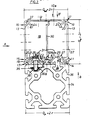
- Fig. 3 shows a K abelkarnalprofil 10a, whose cross-section length Q w of the walls 13 and Q bd the bottom 14 and the cover 12 are twice as large as the corresponding cross-sectional lengths according to Fig. 1.
- the snap-in connections 15, 16 are of the same configuration and dimensioned, as well as the adjacently arranged locking web carriers 24.
- the cover 12 has only two of these locking web carriers.
- the floor 14, on the other hand, has four locking web supports 24, two of which are each arranged in mirror image and are connected to each other to form a channel profile 27 by a connecting web 26.
- Each channel profile 27 encloses a fastening groove 28 which is accessible from the outside through a fastening slot 29.
- a connecting part 36 designed as a screw is arranged with a screw head 36a in the fastening groove 28, while the screw shaft 36b of the connecting part 36 accommodates the loading fastening slot 29 protrudes.
- the screw shaft 36b is screwed into the threaded bore of a clamping piece 38, so that the hollow profile rod 34 and the base 14 are drawn together.
- the clamping piece 38 is a prismatic body that extends perpendicular to the plane of the representation and has approximately the shape of a circular segment.
- the cross section is matched to the width of the fastening slot 29 in such a way that the clamping piece 38 can be brought into the position shown in FIG.
- the connecting part 36 is pushed with the screw head 36a from one end of the fastening groove 28 to an actuation opening 25 in the connecting web 26. Through the actuating opening 25, for example, an Allen key is inserted and the connecting part 36 is screwed into the clamping piece 38. Since two parallel channel trough profiles 27 are present in the cable duct profile 10a, this attachment can also be carried out twice.
- Both channel profiles 27 have terminal fastening strips 31 projecting towards the interior 18, on which installation clamps can be fixed, which are pushed onto these strips 31 in the direction perpendicular to the plane of illustration.
- the strips 31 are L-shaped and arranged opposite one another, so that, in the absence of the intermediate wall 30 shown in FIG. 3, it is also possible to use standard installation clamps which overlap the two strips 31 in a C-shape.
- the intermediate wall 30 is profiled like a channel wall 13, so that it can form a latching connection 15 according to FIG. 3 and, as can be seen in FIG. 3, divides the interior space 18.
- the cable duct profile can be constructed from modularly designed components.
- the cross-sectional lengths Q bd , Q w according to FIG. 1 are each equal to a grid dimension r, that is to say in a ratio of 1: 1.
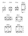
- the profiles of FIGS. 4e, f are wide, but are flat according to FIGS. 4a to 4c. 4g, h are designed in accordance with the profile of FIG.
- the profile of the F ig. 4a has a bottom 14 with a channel profile 27 for attachment to the hollow bar profile 34 of FIG. 3 or a similar profile.
- the cover 12, however, is designed according to FIG. 1.
- the profile of FIG. 4b corresponds to that of FIG. 1, that is to say it has a base part 14 with a cross section of the cover.
- the profile of FIG. 4c has a cover 12 with a bottom cross section.
- the profile of Fig. 4d corresponds to to its double cross-sectional length Q w the profile of FIG. 4a, while the profile of FIG. 4f corresponds to the profile of FIG. 4b up to its double cross-sectional length Q bd .
- the eight cable duct profiles illustrated by FIGS. 4a to 4h can be produced with a total of only six differently profiled parts, which illustrates the universality of the profile system.
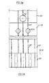
- FIG. 5a shows in view a of FIG. 3 that wall sections 33 of the channel wall 13 which are configured differently in sections in the longitudinal direction and which, for example, have a side outlet opening 32 or two ventilation openings 32a. If such a channel wall section 33 is no longer required, it can be removed and replaced by a desired replacement section.
- FIG. 5b shows in view b of FIG. 3 in the longitudinal direction 42 a duct wall section 40 with a bottom cross section according to FIG. 3 and then a duct section 41 with a cover cross section, five drilling auxiliary grooves 37 being present, as can be seen from view b 'according to FIG. 3 results.
- the hollow profile rods 34 to which the cable duct profiles 10 are attached, also have correspondingly dimensioned cross members have cut lengths, as can be seen from FIG. 3. From this figure it can be seen that the two cross-sections in question each have the same cross-sectional lengths.
Landscapes
- Engineering & Computer Science (AREA)
- Architecture (AREA)
- Civil Engineering (AREA)
- Structural Engineering (AREA)
- Details Of Indoor Wiring (AREA)
- Laying Of Electric Cables Or Lines Outside (AREA)
- Electric Cable Installation (AREA)
- Suspension Of Electric Lines Or Cables (AREA)
Abstract
Description
Die Erfindung bezieht sich auf ein Kabelkanalprofil zur Verlegung von Installationsleitungen od. dgl., mit einem U-förmigen Kanalkörper, dessen von den Kanalwänden gebildete Installationsöffnung von einem Deckel verschlossen ist, der an den Enden der Kanalwände insbesondere außen befestigt ist.The invention relates to a cable duct profile for laying installation lines or the like. With a U-shaped duct body, the installation opening formed by the duct walls is closed by a cover, which is attached in particular to the ends of the duct walls on the outside.
Herkömmliche Kabelkanalprofile werden mit einem U-förmigen Kanalkörper an einer Wand od.dgl. befestigt, mit den zu verlegenden Installationsleitungen bestückt und durch einen Deckel verschlossen, der die Kanalwände außen umklammert. Ein solches Kabelkanalprofil hat einen vorbestimmten unveränderbaren Querschnitt, so daß für unterschiedliche Installationszwecke entsprechend unterschiedlich bemessene Kabelkanalprofile zur Verfügung stehen müssen.Conventional cable duct profiles or the like with a U-shaped duct body on a wall. attached, equipped with the installation cables to be laid and closed by a cover that clasps the duct walls on the outside. Such a cable duct profile has a predetermined, unchangeable cross section, so that ent for different installation purposes speaking differently dimensioned cable duct profiles must be available.
Demgegenüber liegt der Erfindung die Aufgabe zu- grunde, ein Kabelkanalprofil der eingangs genannten Art so zu verbessern, daß es unter teilweiser Weiter- verwendung seiner Bestandteile mit unterschiedlichen Querschnitten hergestellt werden kann, damit entsprechend größere oder kleinere Mengen von Installationsleitungen in seinem Inneren verlegt werden können.In contrast, the invention is based on the object of improving a cable duct profile of the type mentioned at the outset in such a way that it can be manufactured with different cross sections, with partial reuse of its components, so that correspondingly larger or smaller quantities of installation lines can be laid inside .
Diese Aufgabe wird dadurch gelöst, daß die Kanal- wände und der Boden des Kanalkörpers lösbar mitein- ander verbunden und gegen abweichend dimensionierte Wände und/oder Böden austauschbar sind. Für die Erfindung ist von Bedeutung, daß die Kanalwände austauschbar sind. Es können Kanalwände und Böden anderer Dimensionen verwendet werden und es kann damit ein Kabelkanalprofil anderen Querschnitts hergestellt werden. Die Verbindung der Kanalwände und des Bodens erfolgt über Rastverbindungen. Nach Lösen der Rastverbindungen durch vorteilhafte Schwenk- oder Schiebebewegungen quer zur Längsachse des Profils kann der Teileaustausch vorgenommen werden. Es ist denkbar, anstelle der Rastverbindungen Schiebeverbindungen einzusetzen, so daß die zusammenzubauenden Teile in ihrer Längsrichtung durch Ineinanderschieben zusammengebaut werden. Eine derartige Ausbildung der Verbindungsstellen hat aber mehrere Nachteile, vor allem die zum Zusammenbau erforderliche doppelte Montagelänge, aber auch den nicht auszuschließenden Bewegungswiderstand durch Verwerfung der Teile quer zu ihrer Längsrichtung.This object is achieved in that the channel walls and the bottom of the channel body are detachably connected to one another and can be exchanged for walls and / or floors of different dimensions. It is important for the invention that the channel walls are interchangeable. Duct walls and floors of other dimensions can be used and a cable duct profile with a different cross section can be produced with it. The channel walls and the floor are connected via snap-in connections. After loosening the locking connections by means of advantageous swiveling or sliding movements transverse to the longitudinal axis of the profile, the parts can be exchanged. It is conceivable to use sliding connections instead of the latching connections, so that the parts to be assembled are assembled in their longitudinal direction by pushing one into the other. However, such a design of the connection points has several disadvantages, above all the double assembly length required for assembly, but also the movement resistance due to warping of the parts transversely to their longitudinal direction.
Es kann auch der Deckel an den Kanalwänden über Rastverbindungen austauschbar befestigt sein, so daß bei entsprechender Formgestaltung also das Innere des Deckels zur Verlegung von Installationsleitungen herangezogen werden kann. Das könnte insbesondere für Nachinstallationen von Interesse sein, bei denen der einmal unter Einbezug der Wände hergestellte Installationsaufbau nicht geändert oder überhaupt beeinflußt werden soll, z. B. weil der Ausbau der Kanalwände zu aufwendig ist.It can also be exchangeably attached to the cover on the channel walls via snap connections, so that with an appropriate design, the inside of the cover can be used to lay installation cables. This could be of particular interest for retrofits, where the installation structure once made with the inclusion of the walls should not be changed or influenced at all, e.g. B. because the expansion of the channel walls is too expensive.
Der Boden des Kanalkörpers und/oder dessen Deckel haben an ihren Außenkanten in die Richtungen der Kanalwände weisende Widerlagerleisten, die von in das Kanalinnere vorspringenden Hakenleisten hintergriffen sind. Damit erfolgt die Verrastung vorteilhafterweise an den Kanten bzw. im Eckbereich des Profils. Die Hakenleisten einer Rastverbindung einer Kanalwand weisen einen Drucksteg auf, der beim Verhaken der zusammenwirkenden Haken- und Widerlagerleisten unter Überwindung eines Raststegs in eine Rastausnehmung einrastbar ist. Derartige Rastverbindungen gewährleisten einen sicheren Zusammenhalt der zu verrastenden Bauteile, also insbesondere des Bodens mit seien Wänden, aber auch des Deckels, wobei die Rastverbindung so ausgestaltet ist, daß sie die zugehörige Kanalwand im Sinne einer Verspannung einer anderen Rastverbindung oder einer sonstigen lösbaren Verbindung eines Kanalteils mit einem anderen Kanalteil vorzuspannen vermag.The bottom of the channel body and / or its cover have on their outer edges in the direction of the channel walls abutment strips, which are engaged by hook strips projecting into the channel interior. The latching is therefore advantageously carried out at the edges or in the corner region of the profile. The hook strips of a snap-in connection of a duct wall have a pressure web, which can be snapped into a snap-in recess when the cooperating hook and abutment strips are caught while overcoming a snap-in bar. Such locking connections ensure a secure cohesion of the components to be locked, that is, in particular the floor with walls, but also the cover, the locking connection being designed such that it connects the associated channel wall in the sense of bracing another locking connection or another releasable connection of a channel part is able to preload with another duct part.
Um einen leichtgängigen Zusammenbau zu erreichen, weisen die Haken- und Widerlagerleisten kugelgelenkartigen Querschnitt auf.In order to achieve a smooth assembly, the hook and abutment strips have a ball joint-like cross section.
Die Widerlagerleisten des Bodens und des Deckels sowie die Hakenleisten der Kanalwände sind in ihrem Eingriffsbereich jeweils gleich ausgebildet. Infolgedessen können die Rastverbindungen des Bodens und des Deckels vertauscht werden bzw. die Kanalwände sind in ihrer Ebene um 180° gerdreht anzuordnen. Bei unterschiedlicher Ausbildung der Rastverbindungen einer Kanalwand bzw. wenn an einer Kanalwand nur eine einen Drucksteg aufweisende und damit die Kanalwand vorspannende Rastverbindung vorhanden ist, kann diese wahlweise auch am Deckel des Kabelkanalprofils angewendet werden. Vor- teilhafterweise weisen der Boden und der Deckel des Ka- .: belkanals für jede Rastverbindung einen in das Kanalinnere vorspringenden Raststegträger mit je einer Rast- ausnehmung und einem Raststeg auf. Diese Raststegträger sind gleich profiliert, so daß identisch profilierte Haken- und Widerlagerleisten sowie Druckstege für alle Rastverbindungsstellen gleichermaßen zu verwenden sind.The abutment strips of the bottom and the cover as well as the hook strips of the channel walls are each designed identically in their engagement area. As a result, the locking connections of the floor and the Lids are interchanged or the channel walls are to be arranged rotated by 180 ° in their plane. If the latching connections of a channel wall are designed differently or if only one latching connection is present on a channel wall, which has a pressure web and thus prestresses the channel wall, this can optionally be used on the cover of the cable channel profile. Advantageously, the bottom and the cover of the channel for each snap connection have a snap bar support projecting into the channel interior, each with a snap recess and a snap bar. These locking bar supports are profiled the same, so that identically profiled hook and abutment strips and pressure bars can be used equally for all locking connection points.
Um das Kabelkanalprofil in einfacher Weise befestigen zu können, sind die Raststegträger des Bodens mit einem bedarfsweise Betätigungsöffnungen aufweisenden Verbindungssteg tragend miteinander zu einem Rinnenprofil verbunden, und im Boden ist ein längsdurchlaufender, in eine von dem Rinneriprofil umschlassene Befestigungsnut mündender Befestigungsschlitz angeordnet. Das Rinnenprofil ermöglicht die Anordnung eines ununterbrochen längsdurchlaufenden Befestigungsschlitzes, mit dem das Kabelkanalprofil stufenlos an tragendem Untergrund zu befestigen ist.In order to be able to fasten the cable duct profile in a simple manner, the latching web supports of the floor are connected to one another in a supporting manner with a connecting web, if necessary having actuating openings, and in the floor a longitudinally running fastening slot opening into a fastening groove enclosed by the gutter profile is arranged. The channel profile enables the arrangement of an uninterrupted longitudinal fastening slot with which the cable duct profile can be attached to the supporting surface in a stepless manner.
Um größere, nämlich breitere Kabelkanalprofile herzustellen, hat der Boden mindestens zwei nebeneinander angeordnete Rinnenprofile, zwischen denen zwei auf deren Raststegträger abgestimmte Widerlagerleisten angeordnet sind. Beide Rinnenprofile erlauben jeweils die vorbeschriebene Befestigung des Kabelkanalprofils. Darüberhinaus ist das Kanalinnere von einer Zwischenwand unterteilt, die mit dem Boden über eine Rastverbindung lösbar verbunden ist. Das ist beispielsweise erforderlich, um Starkstrom- und Schwachstrominstallationsleitungen voneinander zu trennen. Vorteilhafterweise sind die Zwischenwand und die Kanalwände gleich ausgebildet, was die Herstellung und die Lagerhaltung von Zwischenwänden erleichtert.In order to produce larger, namely wider, cable duct profiles, the base has at least two channel profiles arranged next to one another, between which two abutment strips are arranged which are matched to their latching web supports. Both channel profiles allow the above-described fastening of the cable duct profile. In addition, the interior of the channel is divided by an intermediate wall, which is detachably connected to the floor via a snap connection. That is for example required to separate high-voltage and low-voltage installation lines. Advantageously, the intermediate wall and the channel walls are of identical design, which facilitates the manufacture and storage of intermediate walls.
Um den Aufbau des Kabelkanalprofils zu vereinfachen,, hat der Boden des Kanalkörpers Deckelquerschnitt, oder der Deckel hat Bodenquerschnitt, wenn dies bei Spezialverwendungszwecken erforderlich ist. Die Vertauschbarkeit von Deckel und Boden wird vorteilhafterweise derart eingesetzt, daß in der Längsrichtung des Kabelkanalprofils längenabschnittweise ein Deckelquerschnitt anstelle eines Bodenquerschnitts vorhanden ist. Auf einem Längenabschnitt-könnte also ein Deckelstück an die Stelle eines Bodenstücks treten, beispielsweise wenn keine Befestigungsmöglichkeit gegeben ist und ein einfaches und damit preiswerteres Profil ausreicht, oder wenn mit einem einfachen Deckelprofil Austrittsöffnungen hergestellt werden sollen. In ähnlicher Weise ist in der Längsrichtung des Kabelkanalprofils mindestens ein mit mindestens einer Seiteriaustritts- und/oder Belüftungsöffnung versehener separater Kanalwandabschnitt vorhanden, beispielsweise um einen durch die Seitenaustrittsöffnungen verlegten Kabelbaum leicht ausbauen zu können, 'ohne die Kanalwand insgesamt ausbauen zu müssen. Bei den herkömmlichen Kabelkanälen wird dieses Ziel dadurch erreicht, daß das Kabelkanalprofil über seine gesamte Länge in Abständen geschlitzt wird, so daß die dadurch entstandenen einzelnen Lappen an der jeweils gewünschten Stelle ausgebrochen werden können. Das Schlitzen ist jedoch ein zeitaufwendiger Herstellungsvorgang und durch die Schlitze wird die Kanalwandsteifigkeit herabgesetzt. Beides kann durch die Verwendung der vorgenannten Kanalwandabschnitte vermieden werden.In order to simplify the construction of the cable duct profile, the bottom of the duct body has a cross-section of the cover, or the cover has a cross-section of the base if this is required for special purposes. The interchangeability of the cover and base is advantageously used in such a way that a cover cross-section instead of a base cross-section is present in the longitudinal direction of the cable duct profile. On a length section, a cover piece could therefore take the place of a base piece, for example if there is no fastening possibility and a simple and therefore cheaper profile is sufficient, or if outlet openings are to be produced with a simple cover profile. Similarly, in the longitudinal direction of the cable channel profile at least one provided with at least one Seiteriaustritts- and / or ventilation opening separate duct wall section is provided to be able to, for example, to slightly expand a threaded through the side outlet openings harness, 'without having to remove the channel wall as a whole. In the case of conventional cable ducts, this goal is achieved in that the cable duct profile is slotted at intervals over its entire length, so that the individual tabs which are created can be broken out at the desired location. However, slitting is a time-consuming manufacturing process and the slits reduce the duct wall stiffness. Both can be avoided by using the aforementioned duct wall sections.
In Ausgestaltung der Erfindung stehen die Querschnittslängen des Kabelkanalprofils mit einem Rastermaß im Verhältnis 1 : 1 oder einem ganzzahligen Vielfachen. Damit und mit den vorstehend genannten Merkmalen ist es möglich, ein Kabelkanalprofilsystem herzustellen, daß den Anforderungen nach Vielfältigkeit der gewünschten Querschnitte und der Befestigungs- und Verwendungsmöglichkeiten genügt.In the invention, the cross-sectional lengths of K are portable channel profile with a grid measured in a ratio of 1: 1 or an integer multiple. With this and with the features mentioned above, it is possible to produce a cable duct profile system that meets the requirements for the diversity of the desired cross sections and the mounting and use options.
In Weiterbildung der Erfindung ist das Kabelkanal-. profil mit einem Hohlprofilstab lösbar verbunden, dessen Querschnittslängen auf die des Kabelkanals abgestimmt sind und der mindestens einen mit dem Befestigungs- schlitz des Kabelkanals deckungsgleich angeordneten Befestigungskanal zur Aufnahme eines Verbindungsteils aufweist. Dadurch ist das Kabelkanalprofil mit einem Träger versehen, mit dem es bei Fehlen sonstiger Befestigungsmöglichkeiten insbesondere auch über größere Längen frei verlegt werden kann. Auch die Befestigung des Kabelkänalprofils an Gestellen, die aus derartigen Hohlprofilstäben aufgebaut sind, ist ohne weiteres möglich und erleichtert z.B. das Herstellen von Arbeitstischen unter Verwendung derartiger Hohlprofilstäbe und Kabelkanalprofile. Das Kabelkanalprofil kann auch quer oder unter einem beliebigen Winkel zum Hohlprofilstab verlegt und an diesem befestigt werden.In a further development of the invention, the cable duct. Profile releasably connected to a hollow profile rod, the cross-sectional lengths of which are matched to those of the cable duct and which has at least one fastening duct arranged congruently with the fastening slot of the cable duct for receiving a connecting part. As a result, the cable duct profile is provided with a support with which it can be freely laid, particularly over longer lengths, in the absence of other fastening options. The attachment of the cable duct profile to frames that are constructed from such hollow profile rods is also possible without any problems and facilitates e.g. the production of work tables using such hollow profile bars and cable duct profiles. The cable duct profile can also be laid across or at any angle to the hollow profile rod and attached to it.
Die Erfindung wird anhand von in der Zeichnung dargestellten Ausführungsbeispielen näher erläutert.The invention is explained in more detail with reference to exemplary embodiments shown in the drawing.
Es zeigt:
- Fig. 1 einen Querschnitt eines aus einem Boden, zwei Kanalwänden und einem Deckel bestehenden Kabelkanalprofils,
- Fig. 2 eine vergrößerte Darstellung einer Rastverbindung,
- Fig. 3 einen Querschnitt einer weiteren Ausführungsform eines Kabelkanalprofils mit einem tragenden Hohlprofilstab,
- Fig. 4a bis 4h mehrere schematische Darstellungen von Kanalprofilquerschnitten und
- Fig. 5a, b Seitenansichten eines Kabelkänalprofils in den Richtungen a, b des Profils der Fig. 3.
- 1 shows a cross section of a cable duct profile consisting of a base, two duct walls and a cover,
- 2 is an enlarged view of a locking connection,
- Fig. 3 shows a cross section of another embodiment form of a cable duct profile with a load-bearing hollow profile rod,
- 4a to 4h several schematic representations of channel profile cross sections and
- 5a, b side views of a cable channel profile in the directions a, b of the profile of FIG. 3rd
Das aus Festigkeitsgründen zweckmäßigerweise aus einer Leichtmetallegierung bestehende Kabelkanalprofil 10 der Fig. 1 hat einen Boden 14, zwei daran befestigte Wände 13 und einen Deckel 12, die das Innere 18 des Kabelkanalprofils 10 umschließen, in dem z.B. elektrische Installationsleitungen verlegt werden. Der Boden 14 und die Kanalwände 13 sind mit Rastverbin- dungen 15 zu einem Kanalkörper 11 zusammengebaut, der zwischen den Enden 39 der Kanalwände 13 eine weite Installationsöffnung 18a besitzt.The
Die Kanalwand 13 hat gemäß Fig. 2 an ihrem unteren, dem Boden 14 benachbarten Ende eine L-förmige Hakenleiste 20, die in das Kanalinnere 18 hineinragt und mit ihrem langen L-Schenkel zu der Wand 13 parallel verläuft. Dieser L-Schenkel bzw. die Hakenleiste 20 hintergreift eine an der Außenkante 17 des Bodens 14 vorhandene Widerlagerleiste 19, die vom Boden 14 in Richtung der Kanalwand 13 vorspringt und mit dieser fluchtet. Infolgedessen ergibt sich zwischen den Außenkanten 17 des Kabelkanalprofils der Fig. 1 eine im wesentlichen glatte Außenfläche.2, at its lower end adjacent to the
Die Widerlagerleiste 19 hat wandseitig eine Wulst 19a, die in ihrem die Hakenleiste 20 berührenden Bereich kreisförmigen Querschnitt aufweist. Dementsprechend ist die Hakenleiste 20 in ihrem Berührungsbereich mit der Widerlagerleiste 19 ebenfalls kreisförmig profiliert. An ihrem bodenseitigen Ende hat die Hakenleiste 20 eine zur Widerlagerleiste 19 hin vorspringende Rippe 20a, mit der die Wulst 19a hintergriffen wird. Infolgedessen ist der Querschnitt der Hakenleiste 20 und der Widerlagerleiste 19 im Berührungsbereich beider kugelgelenkartig.The
An der Hakenleiste 20 greift ein Drucksteg 21 an, der etwa senkrecht zur Kanalwand 13 angeordnet ist. Er sorgt dafür, daß die Hakenleiste 20 und die Widerlagerleiste 19 in Eingriff kommen bzw. bleiben. Hierzu wirkt er mit einem Raststegträger 24 zusammen, der einen Raststeg 22 und eine Rastausnehmung 23 aufweist. Der Raststegträger 24 ist so ausgebildet und angeordnet, daß der Drucksteg 21 in der Rastausnehmung 23 fest sitzt und darin festgehalten wird. Dazu ist der Raststegträger 24 mit dem Boden 14 einstückig verbunden. Er hat einen Teil 24a, der im Abstand a parallel zum die Wulst 19a hintergreifenden Schenkel der Hakenleiste 20 verläuft, dann etwa unter 45° von der Senkrechten abweichend zur Mitte des Profilinneren 18 hin verläuft und mit einem waagerechten, den Raststeg 22 bildenden Teil das freie Ende des Druckstegs 21 hintergreift.A pressure web 21, which is arranged approximately perpendicular to the
Der Zusammenbau der Rastverbindung 15 erfolgt derart, daß die Wand 13 zunächst in der strichpunktierten Lage angeordnet wird, in der die Hakenleiste 20 auf der Wulst 19a so aufsitzt, daß der Drucksteg 21 gegen den Raststeg 22 stößt. Danach wird die Wand 13 in Pfeilrichtung 13a und unter Überwindung des Raststegs 22 weitergeschwenkt, bis die Wand 13 ihre mit ausgezogenem Strich dargestellte Lage einnimmt. Diese Lage kann dadurch blockiert werden, daß zwischen der Hakenleiste 20 und dem Teil 24a des Raststegträgers 24 eine etwa a-starke Schraube angeordnet wird, die durch eine mit Hilfe einer Anbohrhilfsrille 37 des Bodens 14 hergestellte Bohrung eingeschraubt wird. Hierzu ist die Anbohrhilfsrille 37 in der Projektion zwischen der Hakenleiste 20 und dem Raststegträger 24 angeordnet.The
Die gestrichelte Lage 13b der Kanalwand 13 deutet an, daß die Kanalwand 13 durch die Rastverbindung 15 nach außen vorgespannt wird, wenn nicht der aus Fig. 1 ersichtliche Deckel 12 auf die beiden Kanalwände 13 aufgesetzt ist. Dieser zieht die vorgespannten Kanalwände 13 in die in Fig..1 ersichtliche, mit ausgezogenen Strichen dargestellte Lage. Der Deckel 12 sitzt mittels . der Rastverbindunge 16 auf den Enden 39 der Kanalwände 13, kann also nur unter Lösen der Rastverbindungen 16 wieder entfernt werden. Wegen der Vorspannung der Ka- nalwände 13'ist im Bereich dieser Rastverbindungen ein gemäß Rastverbindung 15 ausgebildeter Drucksteg nicht erforderlich. Es genügt vielmehr, daß die Haken- und die Widerlagerleisten 19, 20 gleich denen der Rastverbindung 15 ausgebildet sind.The dashed
Fig. 3 zeigt ein Kabelkänalprofil 10a, dessen Querschnittslängen Qw der Wände 13 und Qbd des Bodens 14 bzw. des Deckels 12 doppelt so groß sind, wie die entsprechenden Querschnittslängen gemäß Fig. 1. Die Rastverbindungen 15, 16 sind jedoch gleich ausgebildet und bemessen, wie auch die benachbart angeordneten Raststegträger 24. Der Deckel 12 hat lediglich zwei dieser Raststegträger. Der Boden 14 hat hingegen vier Raststegträger 24, von denen jeweils zwei benachbarte spiegelbildlich angeordnet und durch einen Verbindungssteg 26 tragend miteinander zu einem Rinnenprofil 27 verbunden sind. Jedes Rinnenprofil 27 umschließt eine Befestigungsnut 28, die von außen durch einen Befestigungsschlitz 29 zugänglich ist. Ein als Schraube ausgebildetes Verbindungsteil 36 wird mit einem Schraubenkppf 36a in der Befestigungsnut 28 angeordnet, während der Schraubenschaft 36b des Verbindungsteils 36 den Befestigungsschlitz 29 durchragt.Fig. 3 shows a K
Der Schraubenschaft 36b wird in die Gewindebohrung eines Klemmstücks 38 eingeschraubt, so daß der Hohlprofilstab 34 und der Boden 14 zusammenge- zogen werden. Das Klemmstück 38 ist ein sich senk- recht zur Darstellungsebene erstreckender prisma- tischer Körper, der etwa Kreissegmentform hat. Der Querschnitt ist derart auf die Breite des Befesti- gungsschlitzes 29 abgestimmt, daß das Klemmstück 38 an jeder beliebigen Stelle des Hohlprofilstabs 34 durch den Befestigungssahlitz 29 in die in Fig. 3 dargestellte Lage gebracht werden kann. Das Verbindungsteil 36 wird mit dem Schraubenkopf 36ä von einem Ende der Befesti- gungsnut 28 her bis vor eine Betätigungsöffnung 25 im Verbindungssteg 26 geschoben. Durch die Betätigungsöffnung 25 wird beispielsweise ein Innenmehrkantschlüssel gesteckt und das Verbindungsteil 36 im Klemmstück 38 festgeschraubt. Da bei dem Kabelkanalprofil 10a zwei parallel verlaufende Rinnenprofile 27 vorhanden sind, kann diese Befestigung auch doppelt vorgenommen werden.The
Beide Rinnenprofile 27 besitzen zum Innenraum 18 vorspringende Klemmenbefestigungsleisten 31, an denen Installationsklemmen festgelegt werden können, die in zur Darstellungsebene senkrechter Richtung auf diese Leisten 31 aufgeschoben werden. Die Leisten 31 sind L-förmig und gegenständig angeordnet, so daß bei Nichtvorhandensein der in Fig. 3 dargestellten Zwischenwand 30 auch solche normmäßigen Installationsklemmen verwendet werden können, die die beiden Leisten 31 C-förmig übergreifen.Both channel profiles 27 have terminal fastening strips 31 projecting towards the interior 18, on which installation clamps can be fixed, which are pushed onto these
Zwischen den Rinnenprofilen 27 sind zwei gegenständig angeordnete Hakenleisten 19 vorhanden, die mit ihren benachbarten Raststegträgern 24 Raststellen für die Zwischenwand 30 bilden. Die Zwischenwand 30 ist gleich einer Kanalwand 13 profiliert, so daß sie gemäß Fig. 3 eine Rastverbindung 15 bilden kann und bei der aus Fig. 3 ersichtlichen Anordnung den Innenraum 18 wie ersichtlich unterteilt.Between the channel profiles 27 there are two oppositely arranged hook strips 19 which, with their adjacent locking web supports, have 24 locking points for form the
Aus den Fig. 4a bis 4h wird noch besser deutlich, daß das Kabelkanalprofil aus baukastenartig ausgestalteten Bestandteilen aufgebaut werden kann. Hierzu ist davon auszugehen, daß die Querschnittslängen Qbd, Qw gemäß Fig. 1 jeweils gleich einem Rastermaß r sind, also im Verhältnis 1 : 1 stehen. Kabelkanalprofile . mit gleicher Querschnittsform zeigen die Fig. 4a bis 4c. Bei dem Querschnitt der Fig. 4d ist Qbd zwar = r, jedoch Qw = 2r. Das Profil ist also schmal, aber tief. Demgegenüber sind die Profile der Fig. 4e, f breit, aber entsprechend den Fig. 4a bis 4c flach. Die Profile der Fig. 4g, h sind entsprechend dem Profil der Fig. 3 ausgebildet, also mit Qbd = 2r und Qw = 2r. Die Flächeninhalte der Profile der Fig. 4a bis 4c und 4d bis 4f sowie 4g, h stehen im Verhältnis 1 : 2 : 4. Durch eine derartige Verrasterung der Querschnittslängen bzw. der Querschnittsflächen der möglichen Kabeakanalprofile wird ein sehr vielfältig einsetzbares Baukastensystem geschaffen, das mit vergleichsweise wenig Bestandteilen auskommt und infolgedessen sehr vielseitig und preiswert ist.From FIGS. 4a to 4h it becomes even clearer that the cable duct profile can be constructed from modularly designed components. For this purpose, it can be assumed that the cross-sectional lengths Q bd , Q w according to FIG. 1 are each equal to a grid dimension r, that is to say in a ratio of 1: 1. Cable duct profiles. 4a to 4c show the same cross-sectional shape. In the cross section of FIG. 4d, Q bd is = r, but Q w = 2r. So the profile is narrow but deep. In contrast, the profiles of FIGS. 4e, f are wide, but are flat according to FIGS. 4a to 4c. 4g, h are designed in accordance with the profile of FIG. 3, ie with Q bd = 2r and Q w = 2r. The areas of the profiles of FIGS. 4a to 4c and 4d to 4f as well as 4 g , h are in a ratio of 1: 2: 4. Such a locking of the cross-sectional lengths or the cross-sectional areas of the possible cable channel profiles creates a very versatile modular system that manages with comparatively few components and is therefore very versatile and inexpensive.
Das Profil der Fig. 4ä hat einen Boden 14 mit Rinnenprofil 27 zur Befestigung an dem Hohlstabprofil 34 der Fig..3 oder einem ähnlichen Profil. Der Deckel 12 ist hingegen gemäß Fig. 1 ausgebildet. Das Profil der Fig. 4b entspricht dem der Fig. 1, besitzt also ein Bodenteil 14 mit Deckelquerschnitt. Das Profil der Fig. 4c besitzt hingegen einen Deckel 12 mit Bodenquerschnitt. Das Profil der Fig. 4d entspricht bis auf seine doppelte Querschnittslänge Q w dem Profil der Fig. 4a, während das Profil der Fig. 4f bis auf seine doppelte Querschnittslänge Qbd dem Profil der Fig. 4b entspricht. Die Fig. 4e, h sind bis auf ihre unterschiedlichen Querschnittslängen Qw = r bzw. = 2r gleich profiliert, nämlich gemäß Fig. 3, deren Quer- schnittslängen denen des Profils der Fig. 4g entsprechen, das lediglich mit einem Bodenquerschnitt aufweisenden Deckel 12 abweicht. Die durch die Fig. 4a bis 4h ver- anschaulichten acht Kabelkanalprofile sind mit insge- samt nur sechs voneinander abweichend profilierten Teilen herstellbar, was die Universalität des Profil- systems veranschaulicht.The profile of the F ig. 4a has a bottom 14 with a
Das System bietet darüberhinaus noch den Vorteil, auch in der Längsrichtung der Kabelkanalprofile sehr anpassungsfähig zu sein. Fig. 5a zeigt in der Ansicht a der Fig. 3, daß in Längsrichtung abschnittsweise unterschiedlich ausgestaltete Wandabschnitte 33 der Kanalwand 13 angeordnet werden können, die beispielsweise eine Seitenaustrittsöffnung 32 oder zwei Belüftungsöffnungen 32a aufweisen. Wird ein derartiger Kanalwandabschnitt 33 nicht mehr benötigt, so kann er entfernt und durch einen gewünschten Ersatzabschnitt ersetzt werden.The system also offers the advantage of being very adaptable in the longitudinal direction of the cable duct profiles. FIG. 5a shows in view a of FIG. 3 that
Fig. 5b zeigt in der Ansicht b der Fig. 3 in Längsrichtung 42 einen Kanalwandabschnitt 40 mit Bodenquerschnitt gemäß Fig. 3 und daran anschließend einen Kanalabschnitt 41 mit Deckelquerschnitt, wobei fünf Anbohrhilfsrillen 37 vorhanden sind, wie sich aus der Ansicht b' gemäß Fig. 3 ergibt.FIG. 5b shows in view b of FIG. 3 in the longitudinal direction 42 a
Bei einer derartigen rasterartigen Ausbildung der Kabelkanalprofile ist es vorteilhaft, wenn die Hohlprofilstäbe 34, an denen die Kabelkanalprofile 10 befestigt werden, ebenfalls entsprechend bemessene Querschnittslängen aufweisen, wie sich aus Fig. 3 ergibt. Aus dieser Figur ist ersichtlich, daß die beiden in Rede stehenden Querschnitte jeweils gleich große Querschnittslängen haben. Es ist aber auch möglich, daß das Kabelkanalprofil 10 bzw. 10a oder der Hohlprofilstab 34 voneinander abweichend rasterartig ausgebildet sind, also z.B. Qp = r und Qbd = 2r.With such a grid-like design of the cable duct profiles, it is advantageous if the
Claims (10)
Priority Applications (1)
| Application Number | Priority Date | Filing Date | Title |
|---|---|---|---|
| AT86104623T ATE61165T1 (en) | 1985-05-04 | 1986-04-04 | CABLE DUCT PROFILE FOR LAYING INSTALLATION CABLES OD. DGL. |
Applications Claiming Priority (2)
| Application Number | Priority Date | Filing Date | Title |
|---|---|---|---|
| DE19853516149 DE3516149A1 (en) | 1985-05-04 | 1985-05-04 | CABLE CHANNEL PROFILE FOR LAYING INSTALLATION CABLES OD. DGL. |
| DE3516149 | 1985-05-04 |
Publications (3)
| Publication Number | Publication Date |
|---|---|
| EP0200927A2 true EP0200927A2 (en) | 1986-11-12 |
| EP0200927A3 EP0200927A3 (en) | 1989-01-25 |
| EP0200927B1 EP0200927B1 (en) | 1991-02-27 |
Family
ID=6269892
Family Applications (1)
| Application Number | Title | Priority Date | Filing Date |
|---|---|---|---|
| EP86104623A Expired - Lifetime EP0200927B1 (en) | 1985-05-04 | 1986-04-04 | Cable tray section for laying service conduits or the like |
Country Status (3)
| Country | Link |
|---|---|
| EP (1) | EP0200927B1 (en) |
| AT (1) | ATE61165T1 (en) |
| DE (2) | DE3516149A1 (en) |
Cited By (9)
| Publication number | Priority date | Publication date | Assignee | Title |
|---|---|---|---|---|
| EP0389382A1 (en) * | 1989-03-24 | 1990-09-26 | Ingenierie Boga | Pipeduct, profile for making the same and process for mounting such a duct |
| EP0562499A1 (en) * | 1992-03-24 | 1993-09-29 | del Vesco, Heinz | Cable ducting section |
| EP0654878A1 (en) * | 1993-11-24 | 1995-05-24 | Bocchiotti Societa'per L'industria Elettrotecnica S.P.A. | Raceway for electrical cables or the like with a cover which can be removed only by means of tools |
| WO1997011516A1 (en) * | 1995-09-19 | 1997-03-27 | Andreas Hierzer | Mounting rail for lights |
| EP0767521A2 (en) * | 1995-10-03 | 1997-04-09 | Smc Corporation | Multifunctional conduit |
| WO1997050161A1 (en) * | 1996-06-24 | 1997-12-31 | Hilti Aktiengesellschaft | Cable channel section |
| EP0863594A2 (en) * | 1997-03-06 | 1998-09-09 | Albert Ackermann GmbH & Co. KG | Electrical installation channel |
| EP3595106A1 (en) * | 2018-07-10 | 2020-01-15 | Robert Bosch GmbH | Cable duct |
| EP3240129B1 (en) * | 2016-04-27 | 2023-12-20 | arc2lab GmbH | System for supplying media |
Families Citing this family (4)
| Publication number | Priority date | Publication date | Assignee | Title |
|---|---|---|---|---|
| DE4017330C1 (en) * | 1990-05-30 | 1991-11-07 | Dorma Gmbh + Co. Kg, 5828 Ennepetal, De | |
| DE19532392C2 (en) * | 1995-09-02 | 2003-07-03 | Bosch Gmbh Robert | Cable duct profile for laying installation lines or the like |
| DE102014005548B4 (en) | 2014-04-16 | 2017-04-06 | Detlef Wittkopp | Cable channel system |
| DE102015000289B4 (en) | 2015-01-17 | 2017-10-12 | Detlef Wittkopp | Cable channel system |
Citations (2)
| Publication number | Priority date | Publication date | Assignee | Title |
|---|---|---|---|---|
| DE1236621B (en) * | 1962-07-19 | 1967-03-16 | Albert Theysohn | Set of components for the assembly of cable ducts |
| US3761603A (en) * | 1972-11-14 | 1973-09-25 | Amp Inc | Wiring raceway |
-
1985
- 1985-05-04 DE DE19853516149 patent/DE3516149A1/en not_active Withdrawn
-
1986
- 1986-04-04 EP EP86104623A patent/EP0200927B1/en not_active Expired - Lifetime
- 1986-04-04 DE DE8686104623T patent/DE3677630D1/en not_active Expired - Fee Related
- 1986-04-04 AT AT86104623T patent/ATE61165T1/en not_active IP Right Cessation
Patent Citations (2)
| Publication number | Priority date | Publication date | Assignee | Title |
|---|---|---|---|---|
| DE1236621B (en) * | 1962-07-19 | 1967-03-16 | Albert Theysohn | Set of components for the assembly of cable ducts |
| US3761603A (en) * | 1972-11-14 | 1973-09-25 | Amp Inc | Wiring raceway |
Cited By (14)
| Publication number | Priority date | Publication date | Assignee | Title |
|---|---|---|---|---|
| EP0389382A1 (en) * | 1989-03-24 | 1990-09-26 | Ingenierie Boga | Pipeduct, profile for making the same and process for mounting such a duct |
| FR2644946A1 (en) * | 1989-03-24 | 1990-09-28 | Rotoclip Sa | SHEATH FOR PIPELINE, PROFILE FOR CARRYING IT OUT AND METHOD FOR MOUNTING SUCH A SHEATH |
| EP0562499A1 (en) * | 1992-03-24 | 1993-09-29 | del Vesco, Heinz | Cable ducting section |
| DE4209499A1 (en) * | 1992-03-24 | 1993-09-30 | Giovanni Miranda | Cable duct profile |
| EP0654878A1 (en) * | 1993-11-24 | 1995-05-24 | Bocchiotti Societa'per L'industria Elettrotecnica S.P.A. | Raceway for electrical cables or the like with a cover which can be removed only by means of tools |
| WO1997011516A1 (en) * | 1995-09-19 | 1997-03-27 | Andreas Hierzer | Mounting rail for lights |
| EP0767521A2 (en) * | 1995-10-03 | 1997-04-09 | Smc Corporation | Multifunctional conduit |
| EP0767521A3 (en) * | 1995-10-03 | 1998-07-22 | Smc Corporation | Multifunctional conduit |
| US5949025A (en) * | 1995-10-03 | 1999-09-07 | Smc Corporation | Multifunctional conduit |
| WO1997050161A1 (en) * | 1996-06-24 | 1997-12-31 | Hilti Aktiengesellschaft | Cable channel section |
| EP0863594A2 (en) * | 1997-03-06 | 1998-09-09 | Albert Ackermann GmbH & Co. KG | Electrical installation channel |
| EP0863594A3 (en) * | 1997-03-06 | 2000-01-05 | Albert Ackermann GmbH & Co. KG | Electrical installation channel |
| EP3240129B1 (en) * | 2016-04-27 | 2023-12-20 | arc2lab GmbH | System for supplying media |
| EP3595106A1 (en) * | 2018-07-10 | 2020-01-15 | Robert Bosch GmbH | Cable duct |
Also Published As
| Publication number | Publication date |
|---|---|
| DE3516149A1 (en) | 1986-11-06 |
| EP0200927B1 (en) | 1991-02-27 |
| ATE61165T1 (en) | 1991-03-15 |
| EP0200927A3 (en) | 1989-01-25 |
| DE3677630D1 (en) | 1991-04-04 |
Similar Documents
| Publication | Publication Date | Title |
|---|---|---|
| EP0404284B1 (en) | Framework for a switchbox consisting of a multiple of profiled elements, the said elements having a plurality of bends | |
| DE2125637A1 (en) | Grid-shaped grid construction for suspended ceilings | |
| EP0331690B1 (en) | Ceiling facing | |
| EP0200927B1 (en) | Cable tray section for laying service conduits or the like | |
| DE10136681A1 (en) | frame | |
| EP0244582A2 (en) | Fittings for furniture construction | |
| EP0325985B1 (en) | Ceiling with suspended sections | |
| DE2356225C3 (en) | ||
| EP1994614B1 (en) | Frame construction for a switchgear cabinet, switchgear cabinet and construction kit for the switchgear cabinet | |
| EP0179198A2 (en) | Desk with metal frame | |
| DE2504476A1 (en) | Fixture for polygonal building strut - has one leg of pair tilted under screw force to clamp strut | |
| AT15184U1 (en) | Trunking system with elongated mounting rail | |
| DE19739644C2 (en) | Wall for the cabin of a paint shop | |
| WO2000040874A1 (en) | Guide channel | |
| EP0039467A2 (en) | Spacer | |
| DE19508949C2 (en) | Kit for a support system | |
| DE202006020037U1 (en) | Frame construction for a control cabinet, control cabinet and kit for the control cabinet | |
| DE2241061B2 (en) | Profile tube for the location of vertical wall panel - has cross-shape with internal locking ridges for location in panel grooves | |
| DE2923903A1 (en) | Wall mounted radiator securing structure - includes vertical channel with slots in sides and retaining lugs for horizontal arms | |
| DE1962889C3 (en) | Wall or ceiling cladding with slats | |
| DE2850779A1 (en) | FRAME THAT WORKS WITH ELECTRIC CABLE CHANNELS SO THAT LADDERS CAN HANDLE A WALL OPENING WITHOUT REQUIRING TO WORK ON THE WALL | |
| EP0623530A1 (en) | Overhead conveyor system with a set of profiling strips for mounting | |
| DE19614942B4 (en) | Profile connection for mitred profiles | |
| EP0959536B1 (en) | Multisocket power outlet box | |
| WO2003030322A1 (en) | Base for a control box |
Legal Events
| Date | Code | Title | Description |
|---|---|---|---|
| PUAI | Public reference made under article 153(3) epc to a published international application that has entered the european phase |
Free format text: ORIGINAL CODE: 0009012 |
|
| AK | Designated contracting states |
Kind code of ref document: A2 Designated state(s): AT BE CH DE FR GB IT LI LU NL SE |
|
| PUAL | Search report despatched |
Free format text: ORIGINAL CODE: 0009013 |
|
| AK | Designated contracting states |
Kind code of ref document: A3 Designated state(s): AT BE CH DE FR GB IT LI LU NL SE |
|
| 17P | Request for examination filed |
Effective date: 19890306 |
|
| 17Q | First examination report despatched |
Effective date: 19891218 |
|
| GRAA | (expected) grant |
Free format text: ORIGINAL CODE: 0009210 |
|
| AK | Designated contracting states |
Kind code of ref document: B1 Designated state(s): AT BE CH DE FR GB IT LI LU NL SE |
|
| REF | Corresponds to: |
Ref document number: 61165 Country of ref document: AT Date of ref document: 19910315 Kind code of ref document: T |
|
| GBT | Gb: translation of ep patent filed (gb section 77(6)(a)/1977) | ||
| REF | Corresponds to: |
Ref document number: 3677630 Country of ref document: DE Date of ref document: 19910404 |
|
| ET | Fr: translation filed | ||
| ITF | It: translation for a ep patent filed |
Owner name: STUDIO TORTA SOCIETA' SEMPLICE |
|
| PLBE | No opposition filed within time limit |
Free format text: ORIGINAL CODE: 0009261 |
|
| STAA | Information on the status of an ep patent application or granted ep patent |
Free format text: STATUS: NO OPPOSITION FILED WITHIN TIME LIMIT |
|
| 26N | No opposition filed | ||
| EPTA | Lu: last paid annual fee | ||
| EAL | Se: european patent in force in sweden |
Ref document number: 86104623.3 |
|
| NLS | Nl: assignments of ep-patents |
Owner name: DIPL.-ING. WOLFGANG RIXEN;GERRIT PIES |
|
| REG | Reference to a national code |
Ref country code: FR Ref legal event code: RM |
|
| REG | Reference to a national code |
Ref country code: FR Ref legal event code: TP |
|
| REG | Reference to a national code |
Ref country code: GB Ref legal event code: 713H Ref country code: GB Ref legal event code: 713D |
|
| REG | Reference to a national code |
Ref country code: GB Ref legal event code: 732E |
|
| BECA | Be: change of holder's address |
Free format text: 980429 WOLFGANG *RIXEN;GERRIT *PIES:SPATENWEG 11, D-42655 SOLINGEN; LINDENBAUMSTRASSE 4 D-42659 SOLINGEN |
|
| REG | Reference to a national code |
Ref country code: GB Ref legal event code: IF02 |
|
| PGFP | Annual fee paid to national office [announced via postgrant information from national office to epo] |
Ref country code: NL Payment date: 20040331 Year of fee payment: 19 Ref country code: GB Payment date: 20040331 Year of fee payment: 19 |
|
| PGFP | Annual fee paid to national office [announced via postgrant information from national office to epo] |
Ref country code: SE Payment date: 20040402 Year of fee payment: 19 Ref country code: LU Payment date: 20040402 Year of fee payment: 19 Ref country code: CH Payment date: 20040402 Year of fee payment: 19 |
|
| PGFP | Annual fee paid to national office [announced via postgrant information from national office to epo] |
Ref country code: AT Payment date: 20040405 Year of fee payment: 19 |
|
| PGFP | Annual fee paid to national office [announced via postgrant information from national office to epo] |
Ref country code: FR Payment date: 20040415 Year of fee payment: 19 |
|
| PGFP | Annual fee paid to national office [announced via postgrant information from national office to epo] |
Ref country code: BE Payment date: 20040527 Year of fee payment: 19 |
|
| PGFP | Annual fee paid to national office [announced via postgrant information from national office to epo] |
Ref country code: DE Payment date: 20040628 Year of fee payment: 19 |
|
| PG25 | Lapsed in a contracting state [announced via postgrant information from national office to epo] |
Ref country code: LU Free format text: LAPSE BECAUSE OF NON-PAYMENT OF DUE FEES Effective date: 20050404 Ref country code: IT Free format text: LAPSE BECAUSE OF NON-PAYMENT OF DUE FEES;WARNING: LAPSES OF ITALIAN PATENTS WITH EFFECTIVE DATE BEFORE 2007 MAY HAVE OCCURRED AT ANY TIME BEFORE 2007. THE CORRECT EFFECTIVE DATE MAY BE DIFFERENT FROM THE ONE RECORDED. Effective date: 20050404 Ref country code: GB Free format text: LAPSE BECAUSE OF NON-PAYMENT OF DUE FEES Effective date: 20050404 Ref country code: AT Free format text: LAPSE BECAUSE OF NON-PAYMENT OF DUE FEES Effective date: 20050404 |
|
| PG25 | Lapsed in a contracting state [announced via postgrant information from national office to epo] |
Ref country code: SE Free format text: LAPSE BECAUSE OF NON-PAYMENT OF DUE FEES Effective date: 20050405 |
|
| PG25 | Lapsed in a contracting state [announced via postgrant information from national office to epo] |
Ref country code: LI Free format text: LAPSE BECAUSE OF NON-PAYMENT OF DUE FEES Effective date: 20050430 Ref country code: CH Free format text: LAPSE BECAUSE OF NON-PAYMENT OF DUE FEES Effective date: 20050430 Ref country code: BE Free format text: LAPSE BECAUSE OF NON-PAYMENT OF DUE FEES Effective date: 20050430 |
|
| BERE | Be: lapsed |
Owner name: GERRIT *PIES Effective date: 20050430 Owner name: WOLFGANG *RIXEN Effective date: 20050430 |
|
| PG25 | Lapsed in a contracting state [announced via postgrant information from national office to epo] |
Ref country code: NL Free format text: LAPSE BECAUSE OF NON-PAYMENT OF DUE FEES Effective date: 20051101 Ref country code: DE Free format text: LAPSE BECAUSE OF NON-PAYMENT OF DUE FEES Effective date: 20051101 |
|
| EUG | Se: european patent has lapsed | ||
| REG | Reference to a national code |
Ref country code: CH Ref legal event code: PL |
|
| GBPC | Gb: european patent ceased through non-payment of renewal fee |
Effective date: 20050404 |
|
| PG25 | Lapsed in a contracting state [announced via postgrant information from national office to epo] |
Ref country code: FR Free format text: LAPSE BECAUSE OF NON-PAYMENT OF DUE FEES Effective date: 20051230 |
|
| NLV4 | Nl: lapsed or anulled due to non-payment of the annual fee |
Effective date: 20051101 |
|
| REG | Reference to a national code |
Ref country code: FR Ref legal event code: ST Effective date: 20051230 |
|
| BERE | Be: lapsed |
Owner name: GERRIT *PIES Effective date: 20050430 Owner name: WOLFGANG *RIXEN Effective date: 20050430 |