EP0200652A1 - Wärmeaustauscher mit durch Abstandsgitter quergehaltenem Geradrohrbündel und seine Anwendung - Google Patents
Wärmeaustauscher mit durch Abstandsgitter quergehaltenem Geradrohrbündel und seine Anwendung Download PDFInfo
- Publication number
- EP0200652A1 EP0200652A1 EP86400941A EP86400941A EP0200652A1 EP 0200652 A1 EP0200652 A1 EP 0200652A1 EP 86400941 A EP86400941 A EP 86400941A EP 86400941 A EP86400941 A EP 86400941A EP 0200652 A1 EP0200652 A1 EP 0200652A1
- Authority
- EP
- European Patent Office
- Prior art keywords
- openings
- tubes
- heat exchanger
- grids
- spacer grids
- Prior art date
- Legal status (The legal status is an assumption and is not a legal conclusion. Google has not performed a legal analysis and makes no representation as to the accuracy of the status listed.)
- Withdrawn
Links
- 239000012530 fluid Substances 0.000 claims abstract description 20
- 229910052751 metal Inorganic materials 0.000 claims abstract description 7
- 239000002184 metal Substances 0.000 claims abstract description 7
- 125000006850 spacer group Chemical group 0.000 claims description 43
- 238000003754 machining Methods 0.000 claims description 6
- 238000000465 moulding Methods 0.000 claims description 2
- 238000000926 separation method Methods 0.000 claims description 2
- 230000010339 dilation Effects 0.000 claims 1
- DGAQECJNVWCQMB-PUAWFVPOSA-M Ilexoside XXIX Chemical compound C[C@@H]1CC[C@@]2(CC[C@@]3(C(=CC[C@H]4[C@]3(CC[C@@H]5[C@@]4(CC[C@@H](C5(C)C)OS(=O)(=O)[O-])C)C)[C@@H]2[C@]1(C)O)C)C(=O)O[C@H]6[C@@H]([C@H]([C@@H]([C@H](O6)CO)O)O)O.[Na+] DGAQECJNVWCQMB-PUAWFVPOSA-M 0.000 abstract description 7
- 229910052708 sodium Inorganic materials 0.000 abstract description 7
- 239000011734 sodium Substances 0.000 abstract description 7
- 239000007788 liquid Substances 0.000 abstract description 5
- 238000012423 maintenance Methods 0.000 description 5
- 229910000831 Steel Inorganic materials 0.000 description 4
- 239000002826 coolant Substances 0.000 description 4
- 230000035939 shock Effects 0.000 description 4
- 239000010959 steel Substances 0.000 description 4
- XLYOFNOQVPJJNP-UHFFFAOYSA-N water Substances O XLYOFNOQVPJJNP-UHFFFAOYSA-N 0.000 description 4
- VYZAMTAEIAYCRO-UHFFFAOYSA-N Chromium Chemical compound [Cr] VYZAMTAEIAYCRO-UHFFFAOYSA-N 0.000 description 3
- ZOKXTWBITQBERF-UHFFFAOYSA-N Molybdenum Chemical compound [Mo] ZOKXTWBITQBERF-UHFFFAOYSA-N 0.000 description 2
- 229910052804 chromium Inorganic materials 0.000 description 2
- 239000011651 chromium Substances 0.000 description 2
- 229910052750 molybdenum Inorganic materials 0.000 description 2
- 239000011733 molybdenum Substances 0.000 description 2
- 239000008400 supply water Substances 0.000 description 2
- 238000004381 surface treatment Methods 0.000 description 2
- 230000000712 assembly Effects 0.000 description 1
- 238000000429 assembly Methods 0.000 description 1
- 238000004891 communication Methods 0.000 description 1
- 230000000295 complement effect Effects 0.000 description 1
- 238000010276 construction Methods 0.000 description 1
- 230000007797 corrosion Effects 0.000 description 1
- 238000005260 corrosion Methods 0.000 description 1
- 230000001627 detrimental effect Effects 0.000 description 1
- 238000010438 heat treatment Methods 0.000 description 1
- 238000009434 installation Methods 0.000 description 1
- 229910001338 liquidmetal Inorganic materials 0.000 description 1
- 238000005192 partition Methods 0.000 description 1
- 230000002093 peripheral effect Effects 0.000 description 1
- 238000007747 plating Methods 0.000 description 1
- 230000000135 prohibitive effect Effects 0.000 description 1
- 239000000126 substance Substances 0.000 description 1
- 230000008016 vaporization Effects 0.000 description 1
- 238000009834 vaporization Methods 0.000 description 1
Images

Classifications
-
- F—MECHANICAL ENGINEERING; LIGHTING; HEATING; WEAPONS; BLASTING
- F28—HEAT EXCHANGE IN GENERAL
- F28F—DETAILS OF HEAT-EXCHANGE AND HEAT-TRANSFER APPARATUS, OF GENERAL APPLICATION
- F28F9/00—Casings; Header boxes; Auxiliary supports for elements; Auxiliary members within casings
- F28F9/007—Auxiliary supports for elements
- F28F9/013—Auxiliary supports for elements for tubes or tube-assemblies
- F28F9/0135—Auxiliary supports for elements for tubes or tube-assemblies formed by grids having only one tube per closed grid opening
Definitions
- the invention relates to a heat exchanger with a bundle of straight tubes with circular pitch, the transverse support of which is ensured by spacer grids.
- Straight tube bundle heat exchangers are very often used as steam generators in nuclear reactors, in particular those cooled by liquid metal.
- the reactor coolant allows the heating and the vaporization of feed water which can be circulated inside the tubes or, on the contrary, in contact with the external surface of these tubes.
- the reactor coolant circulates either outside the tubes, inside the envelope of the steam generator containing the bundle, or inside the tubes, respectively.
- the size of the steam generators can be considerable and in particular, in the case of a steam generator with straight tubes, the length of the tubes and of the envelope enclosing the bundle as well as the number of tubes can be very large. It is therefore necessary to use spacer grids fixed inside the envelope of the steam generator, spaced from one another along the length of the tubes, to ensure the transverse maintenance and the intersection of the tubes of the bundle. Such spacer grids must allow not only the maintenance of the tubes against the stresses of the exchange fluids circulating in contact with them at high speed but also the passage of the exchange fluid circulating outside the tubes in the longitudinal direction of the generator. steam. The pressure drop in this fluid change must be as small as possible and it is therefore necessary to provide a large passage section for this fluid relative to the total straight section of the steam generator.
- this arrangement cannot be used in the case of other types of network, for example in the case of networks with circular pitch, that is to say constituted by circular, coaxial and equidistant rows of tubes, inside which the tubes are spaced by a constant arc length.
- networks with circular pitch that is to say constituted by circular, coaxial and equidistant rows of tubes, inside which the tubes are spaced by a constant arc length.
- spacer grids comprising a first set of openings for holding the tubes and a second set of openings for the passage of the coolant.
- spacer grids are however very difficult to machine and are produced by juxtaposing pre-factory plates of limited size.
- the coolant passage openings do not have a constant section over the entire plate and / or the wall thicknesses vary within unacceptable limits.
- the object of the invention is therefore to propose a heat exchanger with a bundle of straight tubes and with circular pitch, the transverse maintenance of which is ensured by spacer grids, comprising an envelope enclosing the tubes inside which circulates a first fluid d exchange, a second exchange fluid circulating in the envelope, outside the tubes, and a set of spacer grids for transversely holding the tubes, fixed inside the envelope, spaced apart from one another according to the length of the tubes and constituted by flat metal plates traversed by a first set of openings arranged in a regular network with circular pitch corresponding to the arrangement of the tubes in the planes of cross section of the bundle and by a second set of openings for the passage of the second exchange fluid, interposed between the openings of the first assembly, this heat exchanger operating under very good thermal and useful conditions ising of spacer grids whose design and machining are relatively simple and satisfactory thermal shock resistance.
- the openings of the second set have a quadrilateral section and a substantially constant area and provide between them and with the openings of the first set of partition walls having a substantially constant thickness.
- the openings constituting the second set have a section in the form of a parallelogram.
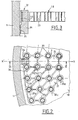
- Fig. 1 is a sectional view through a vertical plane of symmetry of the steam generator with straight tubes.
- Fig. 2 is a fragmentary top view of a spacer grid of the steam generator shown in FIG. 1.
- Fig. 3 is a sectional view along III-III of FIG. 2 showing a support means for the spacer grid.
- a steam generator comprising an external envelope 1 enclosing a bundle of straight tubes 2.
- Each of the tubes 3 of the bundle is fixed at one of its ends in a lower tubular plate 4 and at its other end in a plate upper tubular 5.
- the casing 1 comprises a cylindrical central body constituting the casing of the bundle 2 and two end portions 6 and 7 with a larger diameter sur_lesrise which are fixed the tubular plates 4 and 5, respectively.
- the lower tubular plate 4 is in communication via its external face with a water collector 10 receiving the supply water from the steam generator by a tube 11.
- the collector 10 makes it possible to distribute the supply water in the tubes 3 of the bundle 2, this feed water constituting the first exchange fluid of the steam generator.
- the upper part 7 of the casing 1 receives, via an inlet pipe 12, hot liquid sodium, which then flows from top to bottom in the bundle casing 1, in contact with the outer surface of the tubes 3 and which constitutes the second exchange fluid.
- the feed water circulating in the tubes 3 is thus heated and then vaporized, the vapor formed being recovered by a vapor collector 14 then evacuated by a tube 15.
- the cooled liquid sodium after its circulation in contact with the tubes of the bundle, leaves the envelope 1 by a tube 13 provided in part 6 of this envelope.
- the tubes 3 of the bundle 2 are maintained and braced by spacer grids 18 fixed inside the central body of the envelope. These spacer grids 18 allow both the holding of the tubes in the transverse directions and the passage of the sodium, outside the tubes, in the vertical direction, according to the arrows 19.
- a spacer grid 18 comprising a first set of openings 20 of circular shape and a second set of openings 21 in the form of a quadrilateral.
- the openings 20 have diameters very slightly greater than the diameters of the tubes 3 and are arranged in successive rows 20a, 20b, 20c circular, equidistant and coaxial. In each of the rows, the successive openings 20 have identical spacings in arc distance.
- the tubes 3 of the bundle are engaged in the openings 20 and perfectly maintained inside these, the clearance between the tube 3 and the opening 20 being small.
- tubes of bundle 2 which have a diameter of 15.10 m
- the pitch of the circular network of tubes is 35.10 m and the clearance between the tubes 3 and the openings 20, from 0.2 to 0.5.10 m, depending on the tolerances.
- the openings 21 are in the form of parallelograms with rounded or flattened angles.
- the shape and dimensions of these parallelograms are slightly modified from one row to another and strongly mo- d i f ied in the vicinity of the periphery of the spacer grid, where openings 30 replacing the openings 21 approximately correspond to the half of the section of the openings 21.
- the shape and the distribution of the openings 21 are profoundly modified in the vicinity of the axis XX 'of the spacer grid 18 along which is placed a set of supports 32 of the spacer grid 18 which will be described later in the text.
- the openings 21 however keep the form of quadrilaterals in the vicinity of the axis XX '.
- the shape and distribution of the openings 20 and 21 make it possible to obtain a thickness of the walls 23 for the separation of the openings which is practically constant.
- This wall thickness corresponds to the thickness of metal between two adjacent openings, in a direction contained in the plane of the spacer grid 18.
- the area of the openings 21 remains practically constant over the whole of the spacer grid 18, with the exception of the peripheral zone where the openings 30 have a shape and a size different from those of the openings 21. This constant area allows '' obtain a homogeneous distribution of the liquid sodium flow throughout the section of the spacer grid.
- a spacer grid as shown in FIG. 3 can be obtained by molding or by electrochemical machining of a steel plate.
- the spacer grid 18 shown in FIG. 3 includes notches such as 33 in the direction X'X.
- One in check mark 33 is formed on the spacer grid 18, at each of its ends, in the radial direction X'X and also at each of its ends, in the radial direction perpendicular to X'X.
- each of the support devices 32 of the plate 18 comprises a support element 34 welded at 35 on the inner surface of the casing 1, by means of its lower part and engaged, by its upper part, with the interior of the corresponding notch 33 of the grid 18.
- the upper part of the support element 34 is notched so as to provide bearing edges for the spacer grid 18 engaged with play in the element 34 by its part 33.
- the spacer grid 18 is thus maintained in the vertical directions relative to the casing 1 but remains free to expand in the radial direction.
- the plates used to make the spacer grids can be made of ferritic steel containing 2.25% chromium and 1% molybdenum or steel with 5 / or 9% chromium and 1% molybdenum or even austenitic steel of the grade 316L.
- a surface treatment such as chrome plating or aluminization.
- Such a surface treatment makes it possible to limit the wear of the tubes and the attack of these tubes by fretting corrosion, during the operation of the steam generator.
- the liquid sodium circulates in the vertical direction, outside the tubes, in the casing 1 and passes through the spacer plates by the openings 21 almost exclusively, the clearance between the tubes 3 and the openings 20 being very small.
- the distribution of the sodium flow in the straight sections of the steam generator is thus perfectly homogeneous, which provides excellent thermal operating conditions.
- the small and substantially constant thickness of the walls 23 surrounding the openings 20 and 21 prevents the appearance of thermal gradients at the level of the spacer grids and reduces the risk of damage by thermal shock.
- the main advantages of the heat exchanger according to the invention are therefore very good thermal operation, thanks to a homogeneous distribution of the exchange fluid circulating outside the tubes, a precise arrangement and effective maintenance of the beam tubes, very good thermal shock resistance of the spacer grids and easier design and machining of these spacer grids.
- openings of different forms from those which have been described, for example other forms of quadrilateral, more or less deformed and with rounded angles, to constitute the second set.
- the openings of the first set can be used only for holding the tubes or both for holding the tubes and the passage of the second exchange fluid; for example, three-lobed sections will be used in the second case, for the openings of the first set.
- complementary forms of the openings belonging to one and to the other. of the two assemblies in order to obtain a wall thickness separating these openings and a fluid passage section as constant as possible.
- the heat exchanger according to the invention can not only be used as a steam generator in a nuclear reactor but also for any heat exchange between two fluids in industries such as the chemical industry.
Landscapes
- Engineering & Computer Science (AREA)
- Physics & Mathematics (AREA)
- Thermal Sciences (AREA)
- Mechanical Engineering (AREA)
- General Engineering & Computer Science (AREA)
- Heat-Exchange Devices With Radiators And Conduit Assemblies (AREA)
Applications Claiming Priority (2)
| Application Number | Priority Date | Filing Date | Title |
|---|---|---|---|
| FR8506766 | 1985-05-03 | ||
| FR8506766A FR2581443B1 (fr) | 1985-05-03 | 1985-05-03 | Echangeur de chaleur a faisceau de tubes droits dont le maintien transversal est assure par des grilles entretoises et ses applications |
Publications (1)
| Publication Number | Publication Date |
|---|---|
| EP0200652A1 true EP0200652A1 (de) | 1986-11-05 |
Family
ID=9318938
Family Applications (1)
| Application Number | Title | Priority Date | Filing Date |
|---|---|---|---|
| EP86400941A Withdrawn EP0200652A1 (de) | 1985-05-03 | 1986-04-29 | Wärmeaustauscher mit durch Abstandsgitter quergehaltenem Geradrohrbündel und seine Anwendung |
Country Status (2)
| Country | Link |
|---|---|
| EP (1) | EP0200652A1 (de) |
| FR (1) | FR2581443B1 (de) |
Cited By (2)
| Publication number | Priority date | Publication date | Assignee | Title |
|---|---|---|---|---|
| CN107388584A (zh) * | 2017-08-25 | 2017-11-24 | 东方电气集团东方锅炉股份有限公司 | 一种阔通流的加热器导流装置 |
| CN109237755A (zh) * | 2018-11-08 | 2019-01-18 | 上海士诺净化科技有限公司 | 一种可通用不同换热芯的热交换机 |
Citations (5)
| Publication number | Priority date | Publication date | Assignee | Title |
|---|---|---|---|---|
| FR2128747A1 (de) * | 1971-03-10 | 1972-10-20 | Siemens Ag | |
| US4192374A (en) * | 1977-02-04 | 1980-03-11 | United Kingdom Atomic Energy Authority | Heat exchangers |
| GB2057669A (en) * | 1979-08-15 | 1981-04-01 | Sulzer Ag | Supporting grid for heat exchanger elements and method of making such grids |
| EP0036347A1 (de) * | 1980-03-07 | 1981-09-23 | COMMISSARIAT A L'ENERGIE ATOMIQUE Etablissement de Caractère Scientifique Technique et Industriel | Zwischenwärmeaustauscher für Nuklear-Reaktor mit schnellen Neutronen |
| WO1983000381A1 (en) * | 1981-07-15 | 1983-02-03 | Turbine Metal Technology Inc | Bearing surfaces in nuclear reactor heat exchangers and the like |
Family Cites Families (2)
| Publication number | Priority date | Publication date | Assignee | Title |
|---|---|---|---|---|
| US3989105A (en) * | 1972-02-22 | 1976-11-02 | Georges Trepaud | Heat exchanger |
| FR2293684A2 (fr) * | 1974-12-05 | 1976-07-02 | Trepaud Georges | Echangeur de chaleur a faisceau tubulaire |
-
1985
- 1985-05-03 FR FR8506766A patent/FR2581443B1/fr not_active Expired
-
1986
- 1986-04-29 EP EP86400941A patent/EP0200652A1/de not_active Withdrawn
Patent Citations (5)
| Publication number | Priority date | Publication date | Assignee | Title |
|---|---|---|---|---|
| FR2128747A1 (de) * | 1971-03-10 | 1972-10-20 | Siemens Ag | |
| US4192374A (en) * | 1977-02-04 | 1980-03-11 | United Kingdom Atomic Energy Authority | Heat exchangers |
| GB2057669A (en) * | 1979-08-15 | 1981-04-01 | Sulzer Ag | Supporting grid for heat exchanger elements and method of making such grids |
| EP0036347A1 (de) * | 1980-03-07 | 1981-09-23 | COMMISSARIAT A L'ENERGIE ATOMIQUE Etablissement de Caractère Scientifique Technique et Industriel | Zwischenwärmeaustauscher für Nuklear-Reaktor mit schnellen Neutronen |
| WO1983000381A1 (en) * | 1981-07-15 | 1983-02-03 | Turbine Metal Technology Inc | Bearing surfaces in nuclear reactor heat exchangers and the like |
Cited By (2)
| Publication number | Priority date | Publication date | Assignee | Title |
|---|---|---|---|---|
| CN107388584A (zh) * | 2017-08-25 | 2017-11-24 | 东方电气集团东方锅炉股份有限公司 | 一种阔通流的加热器导流装置 |
| CN109237755A (zh) * | 2018-11-08 | 2019-01-18 | 上海士诺净化科技有限公司 | 一种可通用不同换热芯的热交换机 |
Also Published As
| Publication number | Publication date |
|---|---|
| FR2581443A1 (fr) | 1986-11-07 |
| FR2581443B1 (fr) | 1988-12-02 |
Similar Documents
| Publication | Publication Date | Title |
|---|---|---|
| EP0167418B1 (de) | Doppelwandiges Rohr für Wärmetauscher und dessen Herstellungsverfahren | |
| EP0639741B1 (de) | Wärmetauscher mit Haltevorrichtung für zwischen die Rohre eingelegte Dämpfungsstangen | |
| EP3405723B1 (de) | Kondensationswärmetauscher mit einer wärmetauschervorrichtung | |
| EP0006795B1 (de) | Zwischenwärmeaustauscher für Kernreaktor mit schnellen Neutronen | |
| EP1091169B1 (de) | Dampferzeuger mit einer Verteilungsplatte zur Speisewasserströmungsverbesserung oberhalb der Rohrplatte | |
| FR2832496A1 (fr) | Echangeur de chaleur du type helicoidal | |
| EP0078728B1 (de) | Schwingungsdämpfende Halterung für ein Rohrbündel, insbesondere für einen Dampferzeuger, und Verfahren zum Montieren dieser Halterung | |
| EP0467755B1 (de) | Vorrichtung für schwingungsneutralisierendes Festsetzen von Wärmetauscherrohren | |
| EP0654636B1 (de) | Vorrichtung für schwingungsneutralisierendes Festsetzen von Wärmetauscherrohren und seine Verwendung | |
| EP0955498A1 (de) | Dampferzeuger mit verbesserter Wasserzufuhrvorrichtung | |
| EP0076748A1 (de) | Kernreaktor-Brennstoffbündel | |
| FR2848292A1 (fr) | Plaque d'un echangeur thermique et echangeur thermique a plaques | |
| EP0200652A1 (de) | Wärmeaustauscher mit durch Abstandsgitter quergehaltenem Geradrohrbündel und seine Anwendung | |
| EP0173586B1 (de) | Wärmetauscher mit Rohrbündel, von einer zylindrischen Hülle umgeben, welche radial in einer äusseren Hülle festgehalten wird | |
| EP0173602B1 (de) | Notwärmetauscher zur Kühlung des Primärmittels eines Kernreaktors und Verfahren zu dessen Zusammenbau | |
| FR2694071A1 (fr) | Procédé et dispositif de réglage d'un débit d'eau d'alimentation dans un tube d'un générateur de vapeur. | |
| FR2880106A1 (fr) | Dispositif d'echange de chaleur entre deux fluides comportant des couches de mousse metallique | |
| FR2858845A1 (fr) | Echangeur de chaleur et procede de fabrication | |
| EP0277892A1 (de) | Kühlvorrichtung eines thermonuklearen Fusionsreaktors und modularer Auskleidungsblock zur Herstellung einer Wand für eine derartige Vorrichtung | |
| EP0287422B1 (de) | Zwischenträgergitter zur Querabstützung der Rohre eines Wärmetauscherrohrbündels und Montageverfahren eines solchen Zwischenträgergitters | |
| EP0082780B1 (de) | Dampferzeuger durch Wärmeaustauschung zwischen einem flüssigen, kalorienreichen Metall und Speisewasser | |
| FR2851031A1 (fr) | Generateur de vapeur comportant un dispositif de fourniture d'eau d'alimentation realisant le piegeage de corps etrangers | |
| FR2761453A1 (fr) | Piece destinee en particulier a la fixation de deux corps de chauffe d'un radiateur de chauffage | |
| FR2494421A1 (fr) | Element d'echange de chaleur | |
| BE1001020A3 (fr) | Echangeur de chaleur a metal liquide, avec un rang de tubes. |
Legal Events
| Date | Code | Title | Description |
|---|---|---|---|
| PUAI | Public reference made under article 153(3) epc to a published international application that has entered the european phase |
Free format text: ORIGINAL CODE: 0009012 |
|
| AK | Designated contracting states |
Kind code of ref document: A1 Designated state(s): CH DE FR GB IT LI NL |
|
| 17P | Request for examination filed |
Effective date: 19861010 |
|
| 17Q | First examination report despatched |
Effective date: 19871125 |
|
| STAA | Information on the status of an ep patent application or granted ep patent |
Free format text: STATUS: THE APPLICATION HAS BEEN WITHDRAWN |
|
| 18W | Application withdrawn |
Withdrawal date: 19880329 |
|
| RIN1 | Information on inventor provided before grant (corrected) |
Inventor name: MINGUET, JEAN-LUC Inventor name: TRAITEUR, RENE |