EP0200595B1 - Heizvorrichtung - Google Patents
Heizvorrichtung Download PDFInfo
- Publication number
- EP0200595B1 EP0200595B1 EP19860400646 EP86400646A EP0200595B1 EP 0200595 B1 EP0200595 B1 EP 0200595B1 EP 19860400646 EP19860400646 EP 19860400646 EP 86400646 A EP86400646 A EP 86400646A EP 0200595 B1 EP0200595 B1 EP 0200595B1
- Authority
- EP
- European Patent Office
- Prior art keywords
- fire
- tubes
- fumes
- casing
- air
- Prior art date
- Legal status (The legal status is an assumption and is not a legal conclusion. Google has not performed a legal analysis and makes no representation as to the accuracy of the status listed.)
- Expired - Lifetime
Links
- 238000010438 heat treatment Methods 0.000 title claims description 5
- 239000003517 fume Substances 0.000 claims description 11
- 239000007789 gas Substances 0.000 claims description 9
- XLYOFNOQVPJJNP-UHFFFAOYSA-N water Substances O XLYOFNOQVPJJNP-UHFFFAOYSA-N 0.000 claims description 8
- 238000004140 cleaning Methods 0.000 claims description 5
- 230000000630 rising effect Effects 0.000 claims description 5
- 229910000831 Steel Inorganic materials 0.000 claims description 2
- 239000010959 steel Substances 0.000 claims description 2
- 239000004449 solid propellant Substances 0.000 claims 1
- 238000002485 combustion reaction Methods 0.000 description 14
- 239000003245 coal Substances 0.000 description 12
- 239000002023 wood Substances 0.000 description 12
- 238000003860 storage Methods 0.000 description 10
- 239000003610 charcoal Substances 0.000 description 4
- 239000000779 smoke Substances 0.000 description 4
- 238000004519 manufacturing process Methods 0.000 description 3
- 235000021168 barbecue Nutrition 0.000 description 2
- 239000000446 fuel Substances 0.000 description 2
- 238000009434 installation Methods 0.000 description 2
- 230000005855 radiation Effects 0.000 description 2
- 235000002918 Fraxinus excelsior Nutrition 0.000 description 1
- 229910000746 Structural steel Inorganic materials 0.000 description 1
- 239000002956 ash Substances 0.000 description 1
- 238000009826 distribution Methods 0.000 description 1
- 239000007788 liquid Substances 0.000 description 1
- MMMNTDFSPSQXJP-UHFFFAOYSA-N orphenadrine citrate Chemical compound OC(=O)CC(O)(C(O)=O)CC(O)=O.C=1C=CC=C(C)C=1C(OCCN(C)C)C1=CC=CC=C1 MMMNTDFSPSQXJP-UHFFFAOYSA-N 0.000 description 1
- 238000013021 overheating Methods 0.000 description 1
- 238000009423 ventilation Methods 0.000 description 1
Images

Classifications
-
- F—MECHANICAL ENGINEERING; LIGHTING; HEATING; WEAPONS; BLASTING
- F24—HEATING; RANGES; VENTILATING
- F24B—DOMESTIC STOVES OR RANGES FOR SOLID FUELS; IMPLEMENTS FOR USE IN CONNECTION WITH STOVES OR RANGES
- F24B1/00—Stoves or ranges
- F24B1/18—Stoves with open fires, e.g. fireplaces
- F24B1/191—Component parts; Accessories
- F24B1/195—Fireboxes; Frames; Hoods; Heat reflectors
- F24B1/1952—Multiple fire-boxes
-
- F—MECHANICAL ENGINEERING; LIGHTING; HEATING; WEAPONS; BLASTING
- F24—HEATING; RANGES; VENTILATING
- F24B—DOMESTIC STOVES OR RANGES FOR SOLID FUELS; IMPLEMENTS FOR USE IN CONNECTION WITH STOVES OR RANGES
- F24B1/00—Stoves or ranges
- F24B1/18—Stoves with open fires, e.g. fireplaces
- F24B1/185—Stoves with open fires, e.g. fireplaces with air-handling means, heat exchange means, or additional provisions for convection heating ; Controlling combustion
- F24B1/188—Stoves with open fires, e.g. fireplaces with air-handling means, heat exchange means, or additional provisions for convection heating ; Controlling combustion characterised by use of heat exchange means , e.g. using a particular heat exchange medium, e.g. oil, gas
- F24B1/1885—Stoves with open fires, e.g. fireplaces with air-handling means, heat exchange means, or additional provisions for convection heating ; Controlling combustion characterised by use of heat exchange means , e.g. using a particular heat exchange medium, e.g. oil, gas the heat exchange medium being air only
-
- F—MECHANICAL ENGINEERING; LIGHTING; HEATING; WEAPONS; BLASTING
- F24—HEATING; RANGES; VENTILATING
- F24B—DOMESTIC STOVES OR RANGES FOR SOLID FUELS; IMPLEMENTS FOR USE IN CONNECTION WITH STOVES OR RANGES
- F24B13/00—Details solely applicable to stoves or ranges burning solid fuels
- F24B13/02—Arrangement or mountings of fire-grate assemblies; Arrangement or mountings of linings for fire-boxes, e.g. fire-backs
Definitions
- the invention relates to a heating device, as described in claim 1 and comprising a heat exchanger.
- This heating device is fitted with a fire pit, a waterproof storage store, the inclinations of which allow the embers to be recovered and a maximum of energy produced by them.
- a double chimney flue provided with a special drain with two outlets, one of which is provided with a closing hatch, allows operation with decorative open fire or continuous fire.
- recuperator makes it possible to recover the heat by the radiation of normal and decorative wood fire, by embers and by gases in rising combustion. It is installed in a traditional decorative fireplace. It is used for individuals, small and medium industry. It is constituted by a triple hearth with triple combustion, normal decorative fire on chenets, fire by embers falling in the brazier - combustion chamber which recovers in rising combustion, fire by combustion chamber wood, coal, gas, fuel.
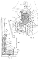
- FIG. 1 shows the sectional view of the exchanger (1) for the production of hot water, or mixed hot water - hot air (fig. 3).
- the exchanger (1 and 1a - fig. 1 - 3 - 5 and 6) is inside the combustion chamber (3).
- the brazier-hearth (2) is a store for storing embers and wood or charcoal at continuous fire. On the top of the brazier-foyer storage store (2) the fire is normal decorative on crawlers and recovers by radiation. As the wood burns, the embers descend into the brazier-hearth warehouse (2) towards the grate (17) at this time the combustion is rising.
- the placement of secondary ventilations (6ter) allows horizontal combustion, the position of the exchanger (17bis) retaining the wood allows reverse and horizontal combustion. So three combustions at a time. All energies are recovered. Secondary air arrives through the inlet (6bis) or through the rear. A fan controlled by a room thermostat or an aquastat can be placed at this entry (6bis) to pulsate the secondary air, which avoids the risks of
- an oil or gas burner can be placed in the combustion chamber (3bis).
- the doors (14 fig. 1 and 5) can be replaced by a sliding plate for adjusting the flow of primary air from the perforated angle (47).
- a grid (17 ter) slightly inclined can be placed to retain the embers and allows the evacuation of the ashes towards the grid (17).
- FIG. 2 represents an interior and exterior view of the brazier-hearth storage warehouse (2) there is the drawer (7) with the primary or secondary air supply (6) for rising light.
- the inclinations of the walls of this brazier-hearth warehouse store (2) allow the oven (32), the loading door with continuous fire (28) allows the loading of wood or coal, the grid (17), the arrivals of secondary air (6ter) and a perforated angle iron (47) for primary air intake for horizontal and inverted fire.
- the casing (48) of the brazier-foyer storage store (2) allows the interlocking of the exchanger (1 and 1bis) and its envelope (19 fig. 3 - 5 and 9) which is closed by a trap door for cleaning (19bis - fig 6).
- FIG 3 shows the exchangers (1 and 1a) which are closed by a removable tip (21) for cleaning the smoke outlets (34).
- the exchangers (1 and 1bis) are provided with a non-figured inlet of fresh air or pulsed by a fan, this air exits through the outlet (22) which can be double.
- FIG. 4 represents a drain (44) with two smoke outlets, the outlet (49) for the normal decorative fire, the outlet (50) for the continuous wood, coal, fuel or gas fire.
- a hatch (43) can close the outlet (49).
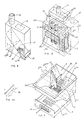
- Figure 5 shows the barbecue, stove and roasting unit.
- Two lateral cabinets (33) on each lateral side of the furnace and the brazier serve as housing for pumps, manometers, batteries, flexon, etc ... or possibly flat heaters. They are not compulsory. They can possibly be incorporated into the decorative fireplace.
- tubular exchangers (1 and 1a) as well as the tubulars (17a) placed inside this decorative fireplace or stove recover and allow to heat a restaurant, a hotel and one or more hot water tanks and storage.
- FIG. 6 represents the brazier-hearth storage warehouse (2) which is hollow under the exchangers (1 and 1a) each of these exchangers being composed of tubular elements. It has watertight doors (14 - fig 5) for continuous fire operation, either wood or charcoal, these doors can be replaced by a sliding plate for adjusting the air flow primary of the perforated angle (47).
- the interior of the brazier-foyer storage store (2) can be provided with tubulars (17 bis) with water circulation connected by the inlets and outlets (11) to the tubular exchangers (1 and 1a), the grid (17 ) retains the embers under the tubulars (17bis).
- a watertight door (28) can be fitted on the front of the brazier-fireplace storage store (2) to allow the loading of wood, coal or the installation of a liquid combustion burner and access for cleaning.
- the tubulars (17 bis) will be placed in the upper part of the brazier, the doors (14) and the grid (17) will be removed and the brazier-foyer storage store (2) in refractory steel will be fully closed and waterproof.
- the exchanger hatch (4) will be closed and the gases and fumes will pass through the second duct (5).
- FIG. 7 represents the exploded view of the brazier-hearth storage store (2) for an automatic charcoal fire which is hollow under the exchangers (1 fig. 9) for the production of hot water and (1bis fig 9) for the hot air production.
- the brazier-hearth store store (2) has a double hearth inside, one for wood combustion, it has a grate (17) which retains the embers, the other for coal combustion with a inclined grid (37) which acts as a burner.
- a zipper movable in all directions (37 bis) is used for cleaning the two fireplaces and provides the primary air which enters through the adjustable hatch (6) of the drawer (7) under the wood firebox. Secondary air arrives through the inlets (6bis) and leaves through the outlets (6ter).
- a motor pulses the primary air through the inlet (6quat.) Under the grid (37).
- the brazier-hearth is composed of a ramp (39) for the automatic lowering of the coal, the second distribution adjustment is made by a manual shutter (36) and separates the two wood and coal hearths.
- Figure 8 shows the coal tank which is incorporated in the chimney and is not visible outside, it is provided with an inlet (40) for receiving coal, it can be located above, on the listed or behind. Inside there can be two inclinations (45) which make it possible to direct the charcoal towards a central hearth or towards two hearths by the exits (42 bis).
- a manual shutter (42) actuated by a lever (41) makes it possible to regulate the automatic arrival of the coal.
- Figure 9 shows the exploded view of the entire recuperator, both water and hot air.
- the gases and smoke pass through the conduits (34) and go towards the outlet (5).
- the conduits (34) are located in a sealed envelope (19) provided with grids (33) which retain the heat by braking the push of air yes is thus further heated and is sent to the outlets (22).
- the gases and smoke from the water recuperator pass through the conduit (3) and go towards the outlet (5).
- Figure 10 shows in detail the manual shutter (36) of the second setting of the arrival of coal.
Landscapes
- Engineering & Computer Science (AREA)
- Chemical & Material Sciences (AREA)
- Combustion & Propulsion (AREA)
- Mechanical Engineering (AREA)
- General Engineering & Computer Science (AREA)
- Solid-Fuel Combustion (AREA)
Claims (3)
- Heizungsvorrichtung mit- eine Herd-Feuerungseinheit (2) mit vertikalen Seitenwänden und schräge vordere und hintere Fläche, die einen Trichter definieren, wobei die schräge vordere Fläche als Stütze für den festen Brennstoff dient und Primärluft zufuhröffnungen (6ter) in der schrägen hinteren Fläche vorgesehen sind;- einen Wärmeaustauscher für einen Wärmeaustausch Rauch/Gas (1bis) bzw. Rauch/Wasser (1) mit in einem Gehäuse (19) angeordneten Röhren (34), das mit einer Rauchabzugsöffnung (5), wobei das Gehäuse (19) auf der Herd-Feuerungseinheit (2) aufgesetzt ist;- wobei die Herd-Feuerungseinheit (2) an seinem freien vorderen Bereich mit einer Tür bzw. Türen (14), die dicht abnehmbar oder gleitend ist bzw. sind und die Öffnung des genannten vorderen Bereiches bedeckt bzw. bedecken, und Sekundärluftzufuhröffnungen (47) zwischen dem bzw. den Türen (14) und dem Gehäuse (19) des Wärmeaustauschers angeordnet sind;- wobei die genannte Heizungsvorrichtung eine Betriebsweise als offenes Feuer mit dekorativen Flammen zulässt, wenn die Tür bzw. Türen in offenener Stellung, bei der der Wärmeaustausch mit dem Wärmeanstauscher (1-1bis) teilweise über die vordere Fläche des Gehäuses (19) und teilweise durch die steigende und umgekehrte Saugwirkung eines Teiles der Gasen und Rauchen durch die die Durchlauf der Gasen und Rauchen gestattenden Röhre (34) hindurch erfolgt, und eine Betribsweise als umgekehrtes Feuer, wenn die Tür bzw. Türen (14) in geschlossener Stellung ist bzw. sind, bei der der Wärmeaustausch nur durch Kontakt zwischen den Rauchen und den Röhren (34) des Wärmeaustauschers erfolgt.
- Vorrichtung nach Anspruch 1, dadurch gekennzeichnet, daß die Röhre (34), die die Durchlauf des Gasen und Rauchen zu die Rauchabzugsöffnung (5) hin, die die in dem aus Stahl bestenden Gehäuse (19) befindliche Luft aufwärmt, durch ein abnehmbares Ansatzstück (21) bedeckt sind, das die Reinigung der Röhre (34) zulässt, und dadurch daß, Gitter (33) zwischen den Röhren (34) so angeordnet sind, um die Wärme zurückzuhalten, zusammen mit einer Bremsung der Luftschübe und damit einer weiteren Erwärmung der Luft.
- Vorrichtung nach Anspruch 1, dadurch gekennzeichnet daß, sie eine Haube (44) enthält, die einen ersten Ausgang (49) für das normale dekorative Feuer, eine das Verschliessen dieses Ausgangs erlaubten Klappe und einen zweiten Ausgang (50) für eine Betriebsweise als Dauerfeuer.
Applications Claiming Priority (6)
| Application Number | Priority Date | Filing Date | Title |
|---|---|---|---|
| FR8504578 | 1985-03-27 | ||
| FR8504578A FR2579726B2 (fr) | 1985-03-27 | 1985-03-27 | Recuperateur de chaleur pour economiser l'energie |
| FR8512105A FR2586088B2 (fr) | 1985-08-07 | 1985-08-07 | Recuperateur de chaleur pour economiser l'energie |
| FR8512105 | 1985-08-07 | ||
| FR8603953 | 1986-03-19 | ||
| FR8603953A FR2596142B2 (fr) | 1986-03-19 | 1986-03-19 | Recuperateur de chaleur pour economiser l'energie |
Publications (3)
| Publication Number | Publication Date |
|---|---|
| EP0200595A2 EP0200595A2 (de) | 1986-11-05 |
| EP0200595A3 EP0200595A3 (en) | 1987-03-04 |
| EP0200595B1 true EP0200595B1 (de) | 1992-03-18 |
Family
ID=27251270
Family Applications (1)
| Application Number | Title | Priority Date | Filing Date |
|---|---|---|---|
| EP19860400646 Expired - Lifetime EP0200595B1 (de) | 1985-03-27 | 1986-03-26 | Heizvorrichtung |
Country Status (2)
| Country | Link |
|---|---|
| EP (1) | EP0200595B1 (de) |
| DE (1) | DE3684356D1 (de) |
Cited By (1)
| Publication number | Priority date | Publication date | Assignee | Title |
|---|---|---|---|---|
| CN104315545A (zh) * | 2014-11-03 | 2015-01-28 | 昆山富凌能源利用有限公司 | 多用途节能灶 |
Families Citing this family (5)
| Publication number | Priority date | Publication date | Assignee | Title |
|---|---|---|---|---|
| FR2761460B1 (fr) * | 1997-03-27 | 1999-05-21 | Cdk International | Dispositif de reglage de la combustion dans une cheminee a double foyer |
| FR2764971B1 (fr) * | 1997-06-18 | 1999-09-10 | Cheminees Seguin Duteriez Sa | Dispositif domestique de combustion combinant foyer ouvert et foyer ferme |
| DE50212891D1 (de) * | 2002-03-15 | 2008-11-27 | Rueegg Cheminee Ag | Herd |
| FR2923288A1 (fr) * | 2007-11-05 | 2009-05-08 | David Lachaize | Dispositif de combustion comportant un foyer superieur et un foyer inferieur,la paroi superieure du foyer inferieur, divisee en deux volets pivotants, formant une sole pour le foyer superieur. |
| FR3012576B1 (fr) * | 2013-10-31 | 2019-03-29 | Jean-Michel Delage | Dispositif de chauffage de type chaudiere et procede de fonctionnement |
Family Cites Families (7)
| Publication number | Priority date | Publication date | Assignee | Title |
|---|---|---|---|---|
| GB280035A (en) * | 1926-11-15 | 1927-11-10 | Karl Mellor Gibbons | Improvements in household ranges |
| GB331943A (en) * | 1929-04-19 | 1930-07-17 | John Warr | Improved method of and means for preventing or diminishing the formation of smoke in the burning of coal in open fireplaces |
| GB366156A (en) * | 1930-01-14 | 1932-02-04 | William Cheyne | Improvements in fire grates |
| FR2471553A1 (fr) * | 1979-12-10 | 1981-06-19 | Mollard Pierre | Capteur de chaleur pouvant etre installe notamment dans une cheminee domestique et procede pour porter a une temperature plus elevee un fluide tel que de l'eau |
| FR2475696A1 (fr) * | 1980-02-13 | 1981-08-14 | Manteau Jean Louis | Chaudiere d'atre |
| DE3126186A1 (de) * | 1980-07-04 | 1982-05-06 | Urban 1040 Wien Egger | "offener kamin zur verfeuerung insbesondere von festem, aber auch gasfoermigem oder fluessigem brennstoff" |
| FR2541429B1 (fr) * | 1983-02-17 | 1986-11-21 | Graziani Adelciso | Recuperateur de chaleur pour economiser l'energie |
-
1986
- 1986-03-26 EP EP19860400646 patent/EP0200595B1/de not_active Expired - Lifetime
- 1986-03-26 DE DE8686400646T patent/DE3684356D1/de not_active Expired - Lifetime
Cited By (1)
| Publication number | Priority date | Publication date | Assignee | Title |
|---|---|---|---|---|
| CN104315545A (zh) * | 2014-11-03 | 2015-01-28 | 昆山富凌能源利用有限公司 | 多用途节能灶 |
Also Published As
| Publication number | Publication date |
|---|---|
| EP0200595A3 (en) | 1987-03-04 |
| EP0200595A2 (de) | 1986-11-05 |
| DE3684356D1 (de) | 1992-04-23 |
Similar Documents
| Publication | Publication Date | Title |
|---|---|---|
| US4147153A (en) | Fireplace air circulation and draft control | |
| US4068650A (en) | Fireplace heating channel | |
| US4088113A (en) | Wood burning automatic swimming pool heater | |
| US4254756A (en) | Fireplace apparatus | |
| EP0200595B1 (de) | Heizvorrichtung | |
| US4368721A (en) | Woodburning stove | |
| GB1580316A (en) | Fireplace space heater | |
| US3934554A (en) | Water and room heater | |
| US4207861A (en) | Fire box gas baffle and hood | |
| US4185610A (en) | Forced air channel baffles | |
| GB2100419A (en) | A stove | |
| US3965886A (en) | Home fireplace heating | |
| RU2087806C1 (ru) | Печь для бань | |
| US4383518A (en) | Heating stove | |
| US2181624A (en) | Fireplace heater | |
| US4230093A (en) | Fireplace door | |
| EP0059151B1 (de) | Heizgerät für Holz mit sichtbarem Feuer für den Einbau | |
| FR2596142A2 (fr) | Recuperateur de chaleur pour economiser l'energie | |
| US2749905A (en) | Fireplace hot air furnace | |
| RU2740962C1 (ru) | Конвекторная печь | |
| CA1125129A (en) | Wood-burning stove | |
| EP0006897B1 (de) | Luftheizung mit forcierter zirkulation | |
| FR2579726A2 (fr) | Recuperateur de chaleur pour economiser l'energie | |
| RU1731U1 (ru) | Печь-камин | |
| FR2586088A2 (fr) | Recuperateur de chaleur pour economiser l'energie |
Legal Events
| Date | Code | Title | Description |
|---|---|---|---|
| PUAI | Public reference made under article 153(3) epc to a published international application that has entered the european phase |
Free format text: ORIGINAL CODE: 0009012 |
|
| AK | Designated contracting states |
Kind code of ref document: A2 Designated state(s): BE CH DE GB IT LI LU NL SE |
|
| PUAL | Search report despatched |
Free format text: ORIGINAL CODE: 0009013 |
|
| AK | Designated contracting states |
Kind code of ref document: A3 Designated state(s): BE CH DE GB IT LI LU NL SE |
|
| 17P | Request for examination filed |
Effective date: 19870901 |
|
| 17Q | First examination report despatched |
Effective date: 19890118 |
|
| GRAA | (expected) grant |
Free format text: ORIGINAL CODE: 0009210 |
|
| AK | Designated contracting states |
Kind code of ref document: B1 Designated state(s): BE CH DE GB IT LI LU NL SE |
|
| REF | Corresponds to: |
Ref document number: 3684356 Country of ref document: DE Date of ref document: 19920423 |
|
| ITF | It: translation for a ep patent filed | ||
| GBT | Gb: translation of ep patent filed (gb section 77(6)(a)/1977) | ||
| PLBE | No opposition filed within time limit |
Free format text: ORIGINAL CODE: 0009261 |
|
| STAA | Information on the status of an ep patent application or granted ep patent |
Free format text: STATUS: NO OPPOSITION FILED WITHIN TIME LIMIT |
|
| 26N | No opposition filed | ||
| ITTA | It: last paid annual fee | ||
| EPTA | Lu: last paid annual fee | ||
| EAL | Se: european patent in force in sweden |
Ref document number: 86400646.5 |
|
| PGFP | Annual fee paid to national office [announced via postgrant information from national office to epo] |
Ref country code: DE Payment date: 19990729 Year of fee payment: 14 |
|
| PG25 | Lapsed in a contracting state [announced via postgrant information from national office to epo] |
Ref country code: DE Free format text: LAPSE BECAUSE OF NON-PAYMENT OF DUE FEES Effective date: 20000331 |
|
| PGFP | Annual fee paid to national office [announced via postgrant information from national office to epo] |
Ref country code: GB Payment date: 20010419 Year of fee payment: 16 |
|
| PGFP | Annual fee paid to national office [announced via postgrant information from national office to epo] |
Ref country code: NL Payment date: 20010430 Year of fee payment: 16 |
|
| REG | Reference to a national code |
Ref country code: GB Ref legal event code: IF02 |
|
| PG25 | Lapsed in a contracting state [announced via postgrant information from national office to epo] |
Ref country code: GB Free format text: LAPSE BECAUSE OF NON-PAYMENT OF DUE FEES Effective date: 20020326 |
|
| PGFP | Annual fee paid to national office [announced via postgrant information from national office to epo] |
Ref country code: SE Payment date: 20020328 Year of fee payment: 17 |
|
| PGFP | Annual fee paid to national office [announced via postgrant information from national office to epo] |
Ref country code: BE Payment date: 20020402 Year of fee payment: 17 |
|
| PGFP | Annual fee paid to national office [announced via postgrant information from national office to epo] |
Ref country code: CH Payment date: 20020701 Year of fee payment: 17 |
|
| PGFP | Annual fee paid to national office [announced via postgrant information from national office to epo] |
Ref country code: LU Payment date: 20020710 Year of fee payment: 17 |
|
| PG25 | Lapsed in a contracting state [announced via postgrant information from national office to epo] |
Ref country code: NL Free format text: LAPSE BECAUSE OF NON-PAYMENT OF DUE FEES Effective date: 20021001 |
|
| GBPC | Gb: european patent ceased through non-payment of renewal fee |
Effective date: 20020326 |
|
| NLV4 | Nl: lapsed or anulled due to non-payment of the annual fee |
Effective date: 20021001 |
|
| PG25 | Lapsed in a contracting state [announced via postgrant information from national office to epo] |
Ref country code: LU Free format text: LAPSE BECAUSE OF NON-PAYMENT OF DUE FEES Effective date: 20030326 |
|
| PG25 | Lapsed in a contracting state [announced via postgrant information from national office to epo] |
Ref country code: SE Free format text: LAPSE BECAUSE OF NON-PAYMENT OF DUE FEES Effective date: 20030327 |
|
| PG25 | Lapsed in a contracting state [announced via postgrant information from national office to epo] |
Ref country code: LI Free format text: LAPSE BECAUSE OF NON-PAYMENT OF DUE FEES Effective date: 20030331 Ref country code: CH Free format text: LAPSE BECAUSE OF NON-PAYMENT OF DUE FEES Effective date: 20030331 Ref country code: BE Free format text: LAPSE BECAUSE OF NON-PAYMENT OF DUE FEES Effective date: 20030331 |
|
| BERE | Be: lapsed |
Owner name: *GRAZIANI ADELCISO Effective date: 20030331 Owner name: *MARTIN JEANNE Effective date: 20030331 |
|
| EUG | Se: european patent has lapsed | ||
| REG | Reference to a national code |
Ref country code: CH Ref legal event code: PL |
|
| PG25 | Lapsed in a contracting state [announced via postgrant information from national office to epo] |
Ref country code: IT Free format text: LAPSE BECAUSE OF NON-PAYMENT OF DUE FEES;WARNING: LAPSES OF ITALIAN PATENTS WITH EFFECTIVE DATE BEFORE 2007 MAY HAVE OCCURRED AT ANY TIME BEFORE 2007. THE CORRECT EFFECTIVE DATE MAY BE DIFFERENT FROM THE ONE RECORDED. Effective date: 20050326 |