EP0200244A2 - Device for joining an envelope with an external element at this envelope - Google Patents
Device for joining an envelope with an external element at this envelope Download PDFInfo
- Publication number
- EP0200244A2 EP0200244A2 EP86200513A EP86200513A EP0200244A2 EP 0200244 A2 EP0200244 A2 EP 0200244A2 EP 86200513 A EP86200513 A EP 86200513A EP 86200513 A EP86200513 A EP 86200513A EP 0200244 A2 EP0200244 A2 EP 0200244A2
- Authority
- EP
- European Patent Office
- Prior art keywords
- balloon
- envelope
- axis
- revolution
- diameter
- Prior art date
- Legal status (The legal status is an assumption and is not a legal conclusion. Google has not performed a legal analysis and makes no representation as to the accuracy of the status listed.)
- Granted
Links
Images
Classifications
-
- B—PERFORMING OPERATIONS; TRANSPORTING
- B64—AIRCRAFT; AVIATION; COSMONAUTICS
- B64B—LIGHTER-THAN AIR AIRCRAFT
- B64B1/00—Lighter-than-air aircraft
- B64B1/58—Arrangements or construction of gas-bags; Filling arrangements
-
- B—PERFORMING OPERATIONS; TRANSPORTING
- B64—AIRCRAFT; AVIATION; COSMONAUTICS
- B64B—LIGHTER-THAN AIR AIRCRAFT
- B64B1/00—Lighter-than-air aircraft
- B64B1/58—Arrangements or construction of gas-bags; Filling arrangements
- B64B1/60—Gas-bags surrounded by separate containers of inert gas
Definitions
- the invention relates to a device for coupling an envelope made of a flexible material with an element external to this envelope. It applies in particular to a device allowing the coupling between the polar zone of a large-volume space balloon and an external structure in order to transmit forces or torques to this balloon.
- One application consists in producing, for operations where the lifting function is predominant (use as cranes, etc.), an aerostatic lifting device associated with a horizontal mechanical winching.
- This device is produced by means of a captive balloon connected to the ground at three fixed or self-propelled points. It may consist of a simple aerostatic balloon, not equipped with its own means of movement or also, for lifting larger loads, of an aerostatic machine produced by the combination of several balloons moored on external structures.
- Such an application allows the movement of large loads over short distances, but is limited in terms of its operational possibilities by the presence of cables and the need for a clear area.
- an improvement can be obtained by making the winching horizontal of the device by means of a separate aircraft, capable of achieving a fixed point (helicopter or airship).
- the present invention proposes to provide a solution to the problems mentioned above and to provide a device for coupling an envelope and an external element making it possible to transmit significant forces to said envelope.
- the essential objective of the invention is to take into account by is to tarite or a large part of an envelope the punctual forces or the couples, transmitted at a pole of said envelope.
- Another object of the invention is to provide a coupling device capable of fulfilling a role of shock absorber between an envelope and an external element.
- Another objective is to provide a coupling device capable of adapting to the differences in shape of an envelope subjected to variations in internal overpressure.
- the application of a transverse force or of a torque at the level of the external element is transmitted to the envelope via the balloon at the level of the contact surface of said balloon and said envelope.
- the surface of this contact surface makes it possible to obtain stresses in the envelope which are much lower than the stresses of shear that this would undergo if the force was transmitted directly to the level of its axis of revolution.
- the transmission of the force by a contact surface remote from the axis of revolution allows this force to be taken into account by a large part of the envelope.
- this small balloon can be provided, at low cost, with a high resistance, sheltering it from any deterioration and allowing it to withstand high overpressures, leading to a stiffening of the contact between this balloon and the envelope.
- the latter comprises, according to another characteristic of the invention, fastening parts having a symmetry of revolution around the axis of revolution of the balloon and delimiting in the orthogonal plane at said axis, diameters of different lengths, the fixing piece in connection with the external element delimiting a diameter of length greater than the diameter of the fixing piece coupled to the envelope.
- the diameter of the fixing piece of larger dimensions is preferably between approximately one third and three-quarters of the diameter of the cross section delimited by the balloon. These dimensions allow the forces to be transmitted with a large lever arm which results in the reduction of the stresses stressing the balloon.
- This device can be used for coupling an envelope whose internal overpressure is variable, with an external element.
- the balloon then comprises means for controlling its internal overpressure, intended to vary said overpressure as a function of the intensity of the force to be transmitted and the contact force between the balloon and the envelope. so as to maintain appropriate contact between said balloon and said envelope.
- the characteristics of the surface of contact between the envelope and the balloon depend essentially, on the one hand on the respective shapes of the envelope and the balloon, and on the other hand on the relative overpressures of this envelope and of this balloon. These characteristics determining the intensity of the effort, torque or transverse effort, that the device is able to transmit to the envelope, it is essential to be able to adapt them to this effort.
- a relative overpressure and a given shape of the envelope and a given force to be transmitted corresponds a relative overpressure of the balloon to obtain an appropriate contact for the transmission of this force. The control of this overpressure of the balloon therefore makes it possible, for a given transmission effort, to maintain appropriate contact between the envelope and the balloon.
- the means for controlling the internal overpressure of the balloon comprise a device for measuring the tensile force urging the coupling means, and means for regulating the overpressure of the balloon as a direct function of said effort. traction and external force to be transmitted to the envelope.
- a modification of the shape of the envelope results in a modification of the characteristics of the contact surface between the envelope and the balloon and, consequently, a variation in the tensile force which tends to uncouple the two envelopes and which is exercised at the level of the coupling means.
- This tensile force therefore gives a representative image of the characteristics of the contact surface and the measuring device, which adapts the internal overpressure of the balloon, as a direct function of this tensile force makes it possible to maintain a contact force suitable for the transmission of external forces to the envelope.
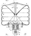
- the coupling device shown by way of example in FIGS. 1 and 2 is intended for coupling an envelope and an external element passing in the extension of the axis of this envelope. It applies in particular for the coupling of the polar zone of a space balloon envelope of generally cylindrical shape and an external element passing in the extension of the longitudinal axis of this balloon.
- This balloon as for example described in the patent FR filed under No. 84.18798, consists in particular of an outer casing 1 made by means of a composite material comprising a longitudinal chain of high resistance, of the "Kevlar" type.
- the gathered ends of this envelope are hung on pole pieces 2, such as for example described in the French patent application recently filed under No. 85.05674 in the name of the applicant, located in the axis of this envelope and able to take up significant efforts.
- the coupling device comprises a balloon 3 produced by means of an envelope having a cylindrical portion which is extended by gathered pleated portions whose edges are attached to pole pieces 4 and 5 arranged at the poles, lower and upper, of the 'envelope on the axis thereof.
- the material of the envelope of the balloon 3 is an airtight composite material having a longitudinal chain based on "Kevlar".
- this envelope is surrounded by a network of longitudinal reinforcements such as 6a located in meridian planes distributed around the envelope and by a network of circumferential reinforcements such as 6b extending transversely along this envelope.
- the longitudinal reinforcements 6a are fixed at the poles of the balloon on the pole pieces 4 and 5, while the circumferential reinforcements 6b are fixed on the envelope of the balloon 3 so that for the inflated state of said balloon, each reinforcement is in contact with the envelope around its entire periphery.
- a bundle of interpolar cables such as 7 arranged inside the envelope in the axis thereof.
- the pole pieces 4 and 5 of annular shape define the upper and lower poles of the balloon and have diameters of different lengths.
- the pole piece with a larger diameter 4 is constituted by an annular rim 4a provided with a groove intended to serve as a housing for blocking the ends of the envelope on its external peripheral face.
- This rim 4a is stiffened in its transverse plane by at least one rigid disc 4b connecting the central core 4c of this pole piece to its periphery 4a.
- this pole piece 4 is integral with drive means intended to drive the balloon in rotation.
- These drive means comprise an assembly 8 fixed relative to the balloon and connected via a hinge pin 9 to a shaft 10 secured to an element external to the balloon 3.
- On this assembly 8 are arranged two motors of entrainment such as 11 which actuate the rotation, about a radial axis perpendicular to the longitudinal axis of the balloon, of two pinions such as 12.
- These pinions 12 are arranged to cooperate with a toothed wheel 13 integral with the rim 4a of the pole piece 4 in order to center this piece in rotation about the longitudinal axis of the balloon.
- the diameter of the pole piece 4 approximately between one third and three-quarters of the diameter of the cross section delimited by the balloon sheath allows, during the rotational training of this balloon to interest all or a large part of the envelope of said balloon and create a lever arm important allowing the transmission of high torques.
- the assembly 8 is in contact by means of thrust bearings 14 with an assembly member 15 mechanically connected to the central core 4c of the pole piece 4 and can therefore thus allow the transmission of transverse forces to the balloon.
- the pole piece 5 of smaller diameter consists of an annular piece as described in the French patent application filed under No. 85.05674 in the name of the applicant.
- This pole piece is integral with a coupling member 16 made of a flexible material of high tensile strength and the other end of which is intended to be fixed to the pole piece 2 of a balloon of large volume such as we we will see it below.
- This coupling member can, for example, consist of a network of cables made of a material of the "Kevlar" type.
- This pole piece 5 is connected to the rim 4a of the pole piece 4 by a network of cables 17 of high tensile strength of the "Kevlar" type. These cables make it possible to ensure stable positioning of the pole piece 4, in particular avoiding the inclination of this piece 4 during the transmission of transverse forces to the balloon 3. This inclination would indeed cause overvoltages in the envelope of the balloon at level of its attachment to the pole piece 4, which could cause deterioration of said balloon.
- the pole piece 5 is, finally, provided with means for admission and rejection of air into the balloon 3.
- These means can be produced by any means known in the prior art. They can for example consist of a 3-way valve which would allow either to evacuate air or to admit air coming from a turbo-compressor or any other equivalent means.
- the balloon as described above, is initially inflated, without relative overpressure with a gas lighter than air, for example helium, in order to make it self-supporting, then brought to its fullness state by admission of 'air.
- This balloon is then positioned using a tripod system or any other known means with respect to the polar region of a large aerostatic balloon, then connected to the polar part 2 of this balloon via the body d 'coupling 16. In this position, the bottom of the balloon is in contact with the polar region of the envelope 1 of the balloon. It should be noted that this contact surface Zl is located in the gathered and therefore the most resistant part of the envelope.
- the identification of the contact between the balloon and the balloon at the level of the contact surface Z1 is carried out by means of an additional admission of air into the balloon.
- the balloon comprises means 19 for measuring the tensile force exerted in the coupling member 16. In fact, this force which tends to uncoupling the envelopes is a direct function of the reaction exerted on the contact surface Z1 and, consequently, of the relative internal overpressure of the balloon. These measurement means therefore control the means for admitting and rejecting air from the balloon in order to obtain an appropriate contact for the force to be transmitted to the envelope.
- the aerostatic balloon coupled to the balloon intended to allow aerostatic piloting by variation of gas masses, the relative interior overpressure and the shape of this balloon are therefore variable.
- the control of the internal overpressure of the balloon is ensured as a function of a reference value of the tensile force exerted in the coupling member 16.
- This value of reference is determined as a function of various parameters relating to the forces to be transmitted to the envelope, to the internal relative pressures of the balloon and of the envelope ...
- This coupling between an aerostatic balloon and a balloon. 3 capable of playing a damper role therefore allows the transmission of forces or significant torques between an external element and an aerostatic balloon, without risk of deterioration of said balloon.
- the diameter of the cross section of the balloon approximately between a quarter and a third of the diameter of the cross section of the ball, allows the transmission of these forces at a contact surface remote from the longitudinal axis of the ball .
- These forces, torque or transverse force are therefore transmitted with a large lever arm which causes a distribution of the stresses in all or a large part of the envelope of the balloon.
- This coupling balloon can be used to couple an aerostatic balloon to any means of traction allowing its horizontal winching. It can also allow the mooring of aerostatic balloons on structures, lower and upper, with a view to producing, by combination of balloon / balloon assemblies, aerostatic airships as shown in FIG. 3.
Abstract
L'invention concerne un dispositif pour l'accouplement d'une enveloppe (1) en matériau souple avec un élément externe. Ce dispositif comprend un ballonnet (3) possédant deux pièces de fixation (4, 5) disposées de façon à définir les pôles, supérieur et inférieur, dudit ballonnet. Une de ces pièces de fixation (5) est accouplée avec l'enveloppe (1) par l'intermédiaire de moyens d'accouplement (2, 16) adaptés pour positionner le ballonnet de façon créer une surface de contact Zl entre lesdits ballonnet et enveloppe. La deuxième pièce de fixation (4) est accouplée avec l'élément externe par l'intermédiaire de moyens de liaisons (8-15) comprenant des moyens d'entraînement aptes entraîner le ballonnet (3) en rotation. Ce dispositif permet notamment la transmission de couples ou d'efforts ponctuels importants entre un élément externe et une enveloppe, en particulier de ballon spatial.The invention relates to a device for coupling an envelope (1) of flexible material with an external element. This device comprises a balloon (3) having two fixing parts (4, 5) arranged so as to define the poles, upper and lower, of said balloon. One of these fixing pieces (5) is coupled with the envelope (1) by means of coupling means (2, 16) adapted to position the balloon so as to create a contact surface Zl between said balloon and envelope . The second fixing part (4) is coupled with the external element by means of connection means (8-15) comprising drive means capable of driving the balloon (3) in rotation. This device allows in particular the transmission of torques or significant punctual forces between an external element and an envelope, in particular of a space balloon.
Description
L'invention concerne un dispositif pour l'accouplement d'une enveloppe réalisée en un matériau souple avec un élément externe à cette enveloppe. Elle s'applique en particulier à un dispositif permettant l'accouplement entre la zone polaire d'un ballon spatial de grand volume et une structure externe en vue de transmettre des efforts ou des couples à ce ballon.The invention relates to a device for coupling an envelope made of a flexible material with an element external to this envelope. It applies in particular to a device allowing the coupling between the polar zone of a large-volume space balloon and an external structure in order to transmit forces or torques to this balloon.
Les problèmes posés par la réalisation de ballons aérostatiques de grands volumes capables de résister à de fortes surpressions tout en présentant un poids relativement modéré sont actuellement solutionnés. Ces ballons, tels que notamment décrits dans le brevet français déposé sous le n° 84.18798 au nom du demandeur sont constitués d'au moins une enveloppe interne contenant de l'hélium, et d'une enveloppe externe contenant les enveloppes internes et de l'air qui confère au ballon sa forme générale cylindrique. L'aptitude de l'enveloppe externe à supporter des surpressions élevées permet l'utilisation de tels ballons pour le transport de charges importantes, le levage des charges et le pilotage vertical aérostatique étant assurés par simple ballastage de l'air.The problems posed by the production of aerostatic balloons of large volumes capable of withstanding high overpressures while having a relatively moderate weight are currently solved. These balloons, as described in particular in the French patent filed under No. 84.18798 in the name of the applicant, consist of at least one internal envelope containing helium, and an external envelope containing the internal envelopes and air which gives the balloon its generally cylindrical shape. The ability of the external envelope to withstand high overpressures allows the use of such balloons for the transport of large loads, the lifting of the loads and the aerostatic vertical control being ensured by simple ballasting of the air.
Une application consiste à réaliser, pour des opérations où la fonction de levage est prépondérante (utilisation en tant que grues...), un dispositif de levage aérostatique associé à un treuillage mécanique horizontal. Ce dispositif est réalisé au moyen d'un ballon captif relié au sol à trois points fixes ou auto-moteurs. Il peut être constitué d'un ballon aérostatique simple, non équipé de moyens propres de déplacement ou également, pour le levage de charges plus importantes, d'un engin aérostatique réalisé par la combinaison de plusieurs ballons amarrés sur des structures externes. Une telle application permet le déplacement de charges importantes sur de courtes distances, mais est limitée au niveau de ses possibilités opérationnelles par la présence des câbles et la nécessité d'une zone dégagée. A cet effet, une amélioration peut être obtenue en réalisant le treuillage horizontal du dispositif au moyen d'un aéronef séparé, apte à réaliser un point fixe (hélicoptère ou dirigeable). Cependant, ces deux applications nécessitent la mise en oeuvre de forces de traction importantes afin de réaliser le treuillage horizontal du ou des ballons. Ces efforts transversaux sont transmis par l'intermédiaire de dispositifs d'accouplement aux pièces polaires des ballons. Compte-tenu des petites dimensions de ces pièces polaires et de l'inertie de l'ensemble, les contraintes s'exerçant dans l'enveloppe au niveau de sa zone polaire sont donc très importantes et peuvent entraîner la détérioration et même la rupture de la liaison entre cette enveloppe et la pièce polaire. Les dispositifs pour l'accouplement de l'enveloppe et des moyens de treuillage horizontal pour un ballon isolé ou de l'enveloppe et de la structure externe, pour une combinaison de ballons, doivent donc être étudiés avec soin afin de permettre la transmission d'efforts transversaux importants.One application consists in producing, for operations where the lifting function is predominant (use as cranes, etc.), an aerostatic lifting device associated with a horizontal mechanical winching. This device is produced by means of a captive balloon connected to the ground at three fixed or self-propelled points. It may consist of a simple aerostatic balloon, not equipped with its own means of movement or also, for lifting larger loads, of an aerostatic machine produced by the combination of several balloons moored on external structures. Such an application allows the movement of large loads over short distances, but is limited in terms of its operational possibilities by the presence of cables and the need for a clear area. To this end, an improvement can be obtained by making the winching horizontal of the device by means of a separate aircraft, capable of achieving a fixed point (helicopter or airship). However, these two applications require the use of large tensile forces in order to achieve the horizontal winching of the balloon (s). These transverse forces are transmitted by means of coupling devices to the pole pieces of the balloons. Given the small dimensions of these pole pieces and the inertia of the assembly, the stresses exerted in the envelope at its polar zone are therefore very high and can cause deterioration and even rupture of the connection between this envelope and the pole piece. The devices for coupling the envelope and the horizontal winching means for an isolated balloon or the envelope and the external structure, for a combination of balloons, must therefore be carefully studied in order to allow the transmission of significant transversal efforts.
Au-delà de ces deux applications, des projets plus ambitieux consistent à réaliser par combinaison de ballons aérostatiques des dirigeables équipés de groupes de propulsion horizontale et de tous les organes auxiliaires nécessaires, en vue du transport de charges lourdes et encombrantes sur de longues distances. La réalisation de ces dirigeables nécessite une étude aérodynamique visant à réduire la traînée des ballons assemblés. Il peut être intéressant d'obtenir cette réduction de la traînée grâce à la mise en rotation de ces ballons autour de leur axe longitudinal. Il est à noter que dans le domaine des structures spatiales gonflables, cette mise en rotation peut également permettre la création d'une pesanteur artificielle. Vu l'inertie des ballons, cet entraînement en rotation oblige à les accoupler aux structures externes au moyen de dispositifs permettant la transmission de couples importants.Beyond these two applications, more ambitious projects consist in realizing by combination of aerostatic balloons airships equipped with horizontal propulsion groups and all the necessary auxiliary organs, for the transport of heavy and bulky loads over long distances. The realization of these airships requires an aerodynamic study aimed at reducing the drag of the assembled balloons. It may be advantageous to obtain this reduction in drag thanks to the rotation of these balloons around their longitudinal axis. It should be noted that in the field of inflatable space structures, this rotation can also allow the creation of an artificial gravity. Given the inertia of the balloons, this rotational drive means that they have to be coupled to the external structures by means of devices allowing the transmission of significant torques.
La présente invention se propose d'apporter une solution aux problèmes ci-dessus évoqués et de fournir un dispositif pour l'accouplement d'une enveloppe et d'un élément externe permettant de transmettre des efforts importants à ladite enveloppe.The present invention proposes to provide a solution to the problems mentioned above and to provide a device for coupling an envelope and an external element making it possible to transmit significant forces to said envelope.
A cet effet, l'objectif essentiel de l'invention est de faire prendre en compte par is to tarite ou une grande partie d'une enveloppe les efforts ponctuels ou les couples, transmis au niveau d'un pôle de ladite enveloppe.To this end, the essential objective of the invention is to take into account by is to tarite or a large part of an envelope the punctual forces or the couples, transmitted at a pole of said envelope.
Un autre objectif de l'invention est de fournir un dispositif d'accouplement apte à remplir un rôle d'amortisseur entre une enveloppe et un élément externe.Another object of the invention is to provide a coupling device capable of fulfilling a role of shock absorber between an envelope and an external element.
Un autre objectif est de fournir un dispositif d'accouplement apte à s'adapter aux différences de forme d'une enveloppe soumise à des variations de surpression intérieure.Another objective is to provide a coupling device capable of adapting to the differences in shape of an envelope subjected to variations in internal overpressure.
Le dispositif visé par l'invention pour l'accouplement d'une enveloppe avec un élément externe comprend :
- - un ballonnet réalisé en un matériau souple et comprenant deux pièces de fixation agencées sur deux zones opposées de la surface externe dudit ballonnet,
- - des moyens d'accouplement de l'enveloppe et d'une des pièces de fixation du ballonnet adaptés pour positionner ledit ballonnet de façon à créer une surface de contact entre le ballonnet et l'enveloppe,
- - des moyens de liaison de l'autre pièce de fixation du ballonnet sur l'élément externe.
- a balloon made of a flexible material and comprising two fixing parts arranged on two opposite zones of the external surface of said balloon,
- means for coupling the envelope and one of the balloon fixing parts suitable for positioning said balloon so as to create a contact surface between the balloon and the envelope,
- - Means for connecting the other attachment part of the balloon to the external element.
Généralement, le ballonnet et l'enveloppe présentent une symétrie de révolution autour d'un axe. Selon la présente invention, le dispositif est alors caractérisé en ce que :
- - les pièces de fixation du ballonnet sont situées sur l'axe de révolution afin de constituer les pôles dudit ballonnet,
- - les moyens d'accouplement sont adaptés pour positionner l'axe de révolution du ballonnet approximativement dans le prolongement de l'axe de révolution de l'enveloppe.
- the balloon fixing parts are located on the axis of revolution in order to constitute the poles of said balloon,
- - The coupling means are adapted to position the axis of revolution of the balloon approximately in the extension of the axis of revolution of the envelope.
Ainsi, comme on le comprendra mieux plus loin, l'application d'un effort transversal ou d'un couple au niveau de l'élément externe est transmis à l'enveloppe par l'intermédiaire du ballonnet au niveau de la surface de contact dudit ballonnet et de ladite enveloppe. La superficie de cette surface de contact permet d'obtenir des contraintes dans l'enveloppe beaucoup plus faibles que les contraintes de cisaillement que subirait celle-ci si l'effort était transmis directement au niveau de son axe de révolution. De plus, la transmission de l'effort par une surface de contact éloignée de l'axe de révolution permet de faire prendre en compte cet effort par une grande partie de l'enveloppe.Thus, as will be better understood below, the application of a transverse force or of a torque at the level of the external element is transmitted to the envelope via the balloon at the level of the contact surface of said balloon and said envelope. The surface of this contact surface makes it possible to obtain stresses in the envelope which are much lower than the stresses of shear that this would undergo if the force was transmitted directly to the level of its axis of revolution. In addition, the transmission of the force by a contact surface remote from the axis of revolution allows this force to be taken into account by a large part of the envelope.
Par contre, la transmission de l'effort de l'élément externe au niveau de l'axe du ballonnet entraine des contraintes importantes dans l'enveloppe dudit ballonnet. A cet effet, ce ballonnet de petites dimensions peut être doté, à moindre coût, d'une résistance élevée le mettent à l'abri de toute détérioration et lui permettant de supporter des surpressions élevées, conduisant à une rigidification du contact entre ce ballonnet et l'enveloppe.On the other hand, the transmission of the force of the external element at the level of the axis of the balloon causes significant stresses in the envelope of said balloon. For this purpose, this small balloon can be provided, at low cost, with a high resistance, sheltering it from any deterioration and allowing it to withstand high overpressures, leading to a stiffening of the contact between this balloon and the envelope.
En outre, afin de diminuer les contraintes sollicitant le ballonnet, celui-ci comprend selon une autre caractéristique de .l'invention, des pièces de fixation présentant une symétrie de révolution autour de l'axe de révolution du ballonnet et délimitant dans le plan orthogonal audit axe, des diamètres de longueurs différentes, la pièce de fixation en liaison avec l'élément externe délimitant un diamètre de longueur supérieure au diamètre de la pièce de fixation accouplée à l'enveloppe.In addition, in order to reduce the stresses on the balloon, the latter comprises, according to another characteristic of the invention, fastening parts having a symmetry of revolution around the axis of revolution of the balloon and delimiting in the orthogonal plane at said axis, diameters of different lengths, the fixing piece in connection with the external element delimiting a diameter of length greater than the diameter of the fixing piece coupled to the envelope.
Le diamètre de la pièce de fixation de dimensions supérieures est compris, préférentiellement, approximativement entre le tiers et les trois-quarts du diamètre de la section transversale délimitée par le ballonnet. Ces dimensions permettent de transmettre les efforts avec un bras de levier important qui entraîne la diminution des contraintes sollicitant le ballonnet.The diameter of the fixing piece of larger dimensions is preferably between approximately one third and three-quarters of the diameter of the cross section delimited by the balloon. These dimensions allow the forces to be transmitted with a large lever arm which results in the reduction of the stresses stressing the balloon.
Ce dispositif peut être utilisé pour l'accouplement d'une enveloppe dont la surpression intérieure est variable, avec un élément externe. Selon la présente invention, le ballonnet comprend alors des moyens de pilotage de sa surpression intérieure, destinés à faire varier ladite surpression en fonction de l'intensité de l'effort à transmettre et de l'effort de contact entre le ballonnet et l'enveloppe de façon à maintenir un contact approprié entre ledit ballonnet et ladite enveloppe.This device can be used for coupling an envelope whose internal overpressure is variable, with an external element. According to the present invention, the balloon then comprises means for controlling its internal overpressure, intended to vary said overpressure as a function of the intensity of the force to be transmitted and the contact force between the balloon and the envelope. so as to maintain appropriate contact between said balloon and said envelope.
En effet, les caractéristiques de la surface de contact entre l'enveloppe et le ballonnet dépendent essentiellement, d'une part des formes respectives de l'enveloppe et du ballonnet, et d'autre part des surpressions relatives de cette enveloppe et de ce ballonnet. Ces caractéristiques déterminant l'intensité de l'effort, couple ou effort transversal, que le dispositif est apte à transmettre è l'enveloppe, il est essentiel de pouvoir les adapter à cet effort. Or, à une surpression relative et une forme données de l'enveloppe et à un effort à transmettre donné, correspond une surpression relative du ballonnet nermettent d'obtenir un contact approprié à la transmission de cet effort. Le pilotage de cette surpression du ballonnet permet donc, pour un effort à transmettre donné, de maintenir un contact approprié entre enveloppe et ballonnet.Indeed, the characteristics of the surface of contact between the envelope and the balloon depend essentially, on the one hand on the respective shapes of the envelope and the balloon, and on the other hand on the relative overpressures of this envelope and of this balloon. These characteristics determining the intensity of the effort, torque or transverse effort, that the device is able to transmit to the envelope, it is essential to be able to adapt them to this effort. However, a relative overpressure and a given shape of the envelope and a given force to be transmitted, corresponds a relative overpressure of the balloon to obtain an appropriate contact for the transmission of this force. The control of this overpressure of the balloon therefore makes it possible, for a given transmission effort, to maintain appropriate contact between the envelope and the balloon.
Selon un mode de réalisation préférentiel, les moyens de pilotage de la surpression intérieure du ballonnet comprennent un dispositif de mesure de l'effort de traction sollicitant les moyens d'accouplement, et des moyens de régulation de la surpression du ballonnet en fonction directe dudit effort de traction et de l'effort externe à transmettre à l'enveloppe.According to a preferred embodiment, the means for controlling the internal overpressure of the balloon comprise a device for measuring the tensile force urging the coupling means, and means for regulating the overpressure of the balloon as a direct function of said effort. traction and external force to be transmitted to the envelope.
En effet, une modification de la forme de l'enveloppe entraîne une modification des caractéristiques de la surface de contact entre l'enveloppe et le ballonnet et, par conséquent, une variation de la force de traction qui tend à désaccoupler les deux enveloppes et qui s'exerce au niveau des moyens d'accouplement. Cet effort de traction donne donc une image représentative des caractéristiques de la surface de contact et le dispositif de mesure, qui adapte la surpression intérieure du ballonnet, en fonction directe de cet effort de traction permet de conserver un effort de contact approprié à la transmission des efforts extérieurs à l'enveloppe.In fact, a modification of the shape of the envelope results in a modification of the characteristics of the contact surface between the envelope and the balloon and, consequently, a variation in the tensile force which tends to uncouple the two envelopes and which is exercised at the level of the coupling means. This tensile force therefore gives a representative image of the characteristics of the contact surface and the measuring device, which adapts the internal overpressure of the balloon, as a direct function of this tensile force makes it possible to maintain a contact force suitable for the transmission of external forces to the envelope.
D'autres caractéristiques, buts et avantages de l'invention se dégageront de la description détaillée qui suit et de l'examen des dessins annexés qui en présentent, à titre d'exemple non limitatif, un mode de réalisation. Sur ces dessins qui font partie intégrante de la description :
- - la figure 1 est une coupe longitudinale d'un dispositif d'accouplement selon l'invention,
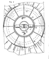
- - la figure 2 en est une coupe selon un plan A.A:,
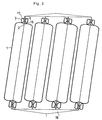
- - la figure 3 est une vue schématique en coupe axiale verticale d'un ensemble aérostatique réalisé au moyen de ballons amarrés sur la structure de cet ensemble par l'intermédiaire du dispositif d'accouplement.
- - Figure 1 is a longitudinal section a coupling device according to the invention,
- - Figure 2 is a section along a plane AA :,
- - Figure 3 is a schematic view in vertical axial section of an aerostatic assembly produced by balloons moored on the structure of this assembly by means of the coupling device.
Le dispositif d'accouplement représenté à titre d'exemple aux figures 1 et 2 est destiné à l'accouplement d'une enveloppe et d'un élément externe passant dans le prolongement de l'axe de cette enveloppe. Il s'applique en particulier pour l'accouplement de la zone polaire d'une enveloppe de ballon spatial de forme générale cylindrique et d'un élément externe passant dans le prolongement de l'axe longitudinal de ce ballon.The coupling device shown by way of example in FIGS. 1 and 2 is intended for coupling an envelope and an external element passing in the extension of the axis of this envelope. It applies in particular for the coupling of the polar zone of a space balloon envelope of generally cylindrical shape and an external element passing in the extension of the longitudinal axis of this balloon.
Ce ballon, tel que par exemple décrit dans le brevet FR déposé sous le n° 84.18798, est constitué notamment d'une enveloppe 1 externe réalisée au moyen d'un matériau composite comprenant une chaîne longitudinale de haute résistance, du type "Kevlar". Les extrémités froncées de cette enveloppe sont accrochées sur des pièces polaires 2, telles que par exemple décrites dans la demande de brevet français récemment déposée sous le n° 85.05674 au nom du demandeur, situées dans l'axe de cette enveloppe et aptes à reprendre des efforts importants.This balloon, as for example described in the patent FR filed under No. 84.18798, consists in particular of an
Le dispositif d'accouplement comprend un ballonnet 3 réalisé au moyen d 'une enveloppe présentant une portion cylindrique qui se prolonge par des portions extrêmes froncées dont les bords sont rattachés sur des pièces polaires 4 et 5 disposées aux pôles, inférieur et supérieur, de l'enveloppe sur l'axe de celle-ci.The coupling device comprises a
Le matériau constitutif de l'enveloppe du ballonnet 3 est un matériau composite étanche à l'air possédant une chaîne longitudinale à base de "Kevlar". En outre, cette enveloppe est entourée d'un réseau de renforts longitudinaux tels que 6a situés dans des plans méridiens répartis autour de l'enveloppe et d'un réseau de renforts circonférentiels tels que 6b s'étendant transversalement le long de cette enveloppe. Les renforts longitudinaux 6a sont fixés au niveau des pôles du ballonnet sur les pièces polaires 4 et 5, tandis que les renforts circonférentiels 6b sont fixés sur l'enveloppe du ballonnet 3 de façon que pour l'état gonflé dudit ballonnet, chaque renfort se trouve eu contact de l'enveloppe sur toute sa périphérie. Sur les pièces polaires est également rattaché un faisceau de câbles interpolaires tels que 7 disposés à l'intérieur de l'enveloppe dans l'axe de celle-ci. Ces renforts, longitudinaux et transversaux et ces câbles sont réalisés en un matériau du type "Kevlar" et tendent à conférer, en combinaison avec la résistance propre de l'enveloppe, une résistance élevée au ballonnet.The material of the envelope of the
Les pièces polaires 4 et 5 de forme annulaire définissent les pôles, supérieur et inférieur, du ballonnet et possèdent des diamètres de longueurs différentes. La pièce polaire de diamètre supérieur 4 est constituée par une jante annulaire 4a munie d'une gorge destinée à servir de logement de blocage des extrémités de l'enveloppe sur sa face périphérique externe. Cette jante 4a est raidie dans son plan transversal par au moins un disque 4b rigide reliant le noyau central 4c de cette pièce polaire à sa périphérie 4a.The
De plus, cette pièce 4 polaire est solidaire de moyens d'entraînement destinés à entraîner le ballonnet en rotation. Ces moyens d'entraînement comprennent un ensemble 8 fixe par rapport au ballonnet et relié par l'intermédiaire d'un axe d'articulation 9 à un arbre 10 solidaire d'un élément externe au ballonnet 3. Sur cet ensemble 8 sont agencés deux moteurs d'entralnement tels que 11 qui actionnent la mise en rotation, autour d'un axe radial perpendiculaire à l'axe longitudinal du ballonnet, de deux pignons tels que 12. Ces pignons 12 sont agencés pour coopérer avec une roue 13 dentée solidaire de la jante 4a de la pièce 4 polaire afin d'entralner cette pièce en rotation autour de l'axe longitudinal du ballonnet.In addition, this
Le diamètre de la pièce polaire 4, approximativement compris entre le tiers et les trois-quarts du diamètre de la section transversale délimitée par la gaine du ballonnet permet, lors de l'entraînement en rotation de ce ballonnet d'intéresser la totalité ou une grande partie de l'enveloppe dudit ballonnet et de créer un bras de levier importent permettant la transmission de couples élevés.The diameter of the
En outre, l'ensemble 8 se trouve en contact par l'intermédiaire de butées à billes 14 avec un organe d'assemblage 15 relié mécaniquement au noyau 4c central de la pièce polaire 4 et peut donc ainsi permettre la transmission d'efforts transversaux au ballonnet.In addition, the
La pièce 5 polaire de diamètre inférieur est constituée d'une pièce annulaire telle que décrite dans la demande de brevet français déposée sous le n° 85.05674 au nom du demandeur. Cette pièce polaire est solidaire d'un organe d'accouplement 16 réalisé en un matériau flexible de haute résistance a la traction et dont l'autre extrémité est destinée à être fixée sur la pièce polaire 2 d'un ballon de grand volume tel que nous le verrons ci-après. Cet organe d'accouplement peut, par exemple, être constitué d'un réseau de câbles en un matériau du type "Kevlar".The
Cette pièce polaire 5 est reliée à la jante 4a de la pièce 4 polaire par un réseau de câbles 17 de haute résistance à la traction du type "Kevlar". Ces câbles permettent d'assurer un positionnement stable de la pièce polaire 4, évitant notamment l'inclinaison de cette pièce 4 lors de la transmission d'efforts transversaux au ballonnet 3. Cette inclinaison entrainerait en effet des surtensions dans l'enveloppe du ballonnet au niveau de son accrochage sur la pièce polaire 4, qui pourraient provoquer une détérioration dudit ballonnet.This
De plus, la présence de ces câbles 17, en association avec la présence du faisceau de câbles 7 interpolaires permet par une opération facile le réglage de la distance entre pôles. Ce réglage permet notamment de réduire cette distance interpolaire de façon à maintenir la pièce polaire 5 de diamètre inférieur, en retrait par rapport au fond froncé du ballonnet 3.In addition, the presence of these
La pièce polaire 5 est, enfin, munie de moyens d'admission et de rejet d'air dans le ballonnet 3. Ces moyens, non représentés sur les dessins annexés, peuvent être réalisés par tout moyen connu de la technique actuelle. Ils peuvent par exemple être constitués d'une vanne 3 voies qui permettrait, soit d'évacuer de l'air, soit d'admettre de l'air parvenant d'un turbo-compresseur ou tout autre moyen équivalent.The
Le ballonnet, tel que décrit ci-avant, est initialement gonflé, sans surpression relative avec un gaz plus léger que l'air, par exemple de l'hélium, afin de le rendre autoportable, puis amené à son état de plénitude par admission d'air. Ce ballonnet est ensuite positionné grâce à un système de tripode ou tout autre moyen connu en regard de la zone polaire d'un ballon aérostatique de grand volume, puis relié à la pièce 2 polaire de ce ballon par l'intermédiaire de l'organe d'accouplement 16. Dans cette position, le fond du ballonnet se trouve en contact avec la zone polaire de l'enveloppe 1 du ballon. Il est à noter que cette surface de contact Zl se trouve dans la partie froncée et donc la plus résistante de l'enveloppe.The balloon, as described above, is initially inflated, without relative overpressure with a gas lighter than air, for example helium, in order to make it self-supporting, then brought to its fullness state by admission of 'air. This balloon is then positioned using a tripod system or any other known means with respect to the polar region of a large aerostatic balloon, then connected to the
La Tigidification du contact entre le ballonnet et le ballon au niveau de la surface de contact Zl est réalisé au moyen d'une admission supplémentaire d'air dans le ballonnet. Afin de pouvoir contrôler les contraintes s'exerçant entre les enveloppes au niveau de leur surface de contact Zl, le ballonnet comprend des moyens de mesure 19 de la force de traction s'exerçant dans l'organe d'accouplement 16. En effet, cette force qui tend à désaccoupler les enveloppes est une fonction directe de la réaction s'exerçant au niveau de la surface de contact Z1 et, par conséquent, de la surpression intérieure relative du ballonnet. Ces moyens de mesure pilotent donc les moyens d'admission et de rejet d'air du ballonnet afin d'obtenir un contact approprié à l'effort à transmettre à l'enveloppe.The identification of the contact between the balloon and the balloon at the level of the contact surface Z1 is carried out by means of an additional admission of air into the balloon. In order to be able to control the stresses exerted between the envelopes at their contact surface Z1, the balloon comprises means 19 for measuring the tensile force exerted in the
En outre, le ballon aérostatique accouplé au ballonnet visant à permettre un pilotage aérostatique par variation de masses gazeuses, la surpression relative intérieure et la forme de ce ballon sont donc variables.In addition, the aerostatic balloon coupled to the balloon intended to allow aerostatic piloting by variation of gas masses, the relative interior overpressure and the shape of this balloon are therefore variable.
Afin de conserver un contact approprié entre enveloppes respectives permettant la transmission des efforts malgré la variation de surpression intérieure du ballon, le pilotage de la surpression intérieure du ballonnet est assuré en fonction d'une valeur de référence de la force de traction s'exerçant dans l'organe d'accouplement 16. Cette valeur de référence est déterminée en fonction de différents paramètres relatifs aux efforts à transmettre à l'enveloppe, aux pressions relatives intérieures du ballonnet et de l'enveloppe...In order to maintain an appropriate contact between the respective envelopes allowing the transmission of forces despite the variation in the internal overpressure of the balloon, the control of the internal overpressure of the balloon is ensured as a function of a reference value of the tensile force exerted in the
Cet accouplement entre un ballon aérostatique et un ballonnet. 3 apte à jouer un rôle d'amortisseur, permet donc la transmission d'efforts ou de couples importants entre un élément externe et un ballon aérostatique, sans risque de détérioration dudit ballon. En effet, le diamètre de la section transversale du ballonnet compris approximativement entre le quart et le tiers du diamètre de la section transversale du ballon, permet la transmission de ces efforts au niveau d'une surface de contact éloignée de l'axe longitudinal du ballon. Ces efforts, couple ou effort transversal, sont donc transmis avec un bras de levier important qui entraine une répartition des contraintes dans la totalité ou une grande partie de l'enveloppe du ballon. Les pièces polaires mécaniques de petite taille sont donc protégées, et ce d'autant plus que la flexibilité de l'organe d'accouplement 16 permet un léger désaxement des deux enveloppes, lors de la transmission d'efforts transversaux par exemple, sans création de contraintes de cisaillement élevées au niveau de la liaison entre les pièces 2 et 5 polaires et les enveloppes respectives du ballon et du ballonnet.This coupling between an aerostatic balloon and a balloon. 3 capable of playing a damper role, therefore allows the transmission of forces or significant torques between an external element and an aerostatic balloon, without risk of deterioration of said balloon. Indeed, the diameter of the cross section of the balloon approximately between a quarter and a third of the diameter of the cross section of the ball, allows the transmission of these forces at a contact surface remote from the longitudinal axis of the ball . These forces, torque or transverse force, are therefore transmitted with a large lever arm which causes a distribution of the stresses in all or a large part of the envelope of the balloon. The small mechanical pole pieces are therefore protected, all the more since the flexibility of the
Ce ballonnet d'accouplement peut être utilisé pour accoupler un ballon aérostatique à tout moyen de traction permettant son treuillage horizontal. Il peut également permettre l'amarrage de ballons aérostatiques sur des structures, inférieure et supérieure, en vue de réaliser par combinaison d'ensembles ballonnets/ballon des dirigeables aérostatiques tels que représentés fig. 3.This coupling balloon can be used to couple an aerostatic balloon to any means of traction allowing its horizontal winching. It can also allow the mooring of aerostatic balloons on structures, lower and upper, with a view to producing, by combination of balloon / balloon assemblies, aerostatic airships as shown in FIG. 3.
Claims (13)
Applications Claiming Priority (2)
| Application Number | Priority Date | Filing Date | Title |
|---|---|---|---|
| FR8506465A FR2581022B1 (en) | 1985-04-25 | 1985-04-25 | DEVICE FOR COUPLING AN ENVELOPE WITH AN ELEMENT EXTERNAL TO THE ENVELOPE |
| FR8506465 | 1985-04-25 |
Publications (3)
| Publication Number | Publication Date |
|---|---|
| EP0200244A2 true EP0200244A2 (en) | 1986-11-05 |
| EP0200244A3 EP0200244A3 (en) | 1987-10-28 |
| EP0200244B1 EP0200244B1 (en) | 1989-07-19 |
Family
ID=9318762
Family Applications (1)
| Application Number | Title | Priority Date | Filing Date |
|---|---|---|---|
| EP86200513A Expired EP0200244B1 (en) | 1985-04-25 | 1986-03-27 | Device for joining an envelope with an external element at this envelope |
Country Status (5)
| Country | Link |
|---|---|
| US (1) | US4696444A (en) |
| EP (1) | EP0200244B1 (en) |
| CA (1) | CA1264700A (en) |
| DE (1) | DE3664443D1 (en) |
| FR (1) | FR2581022B1 (en) |
Cited By (1)
| Publication number | Priority date | Publication date | Assignee | Title |
|---|---|---|---|---|
| FR2669602A1 (en) * | 1990-11-22 | 1992-05-29 | R P Dev Sarl | Lighter-than-air machine including at least one variable-geometry cylindrical balloon |
Families Citing this family (9)
| Publication number | Priority date | Publication date | Assignee | Title |
|---|---|---|---|---|
| JPH07501650A (en) * | 1991-11-29 | 1995-02-16 | モトローラ・インコーポレイテッド | Battery with protection circuit |
| FR2790441B1 (en) | 1999-03-02 | 2001-06-01 | Regipa And Partners Dev | AEROSTATIC ASSEMBLY INCLUDING A PLURALITY OF PRESSURIZED BALLOONS |
| AU2000274254A1 (en) | 2000-10-03 | 2002-04-15 | Interactive Star | Aerostatic assembly comprising a plurality of pressurised balloons |
| US9611024B2 (en) | 2011-08-03 | 2017-04-04 | Lockheed Martin Corporation | Ballonet measurement system |
| US9845141B2 (en) | 2012-12-07 | 2017-12-19 | Raven Industries, Inc. | Atmospheric balloon system |
| US9327817B1 (en) | 2014-02-03 | 2016-05-03 | Google Inc. | Ballonet for a balloon |
| US20160221661A1 (en) | 2015-02-02 | 2016-08-04 | Derek Lee Bohannon | Tendon sleeve for high-altitude balloon and system for making the same |
| US10780997B1 (en) * | 2018-07-09 | 2020-09-22 | National Technology & Engineering Solutions Of Sandia, Llc | Systems and methods for shock-resistant memory devices |
| US11433984B2 (en) | 2019-04-19 | 2022-09-06 | Lockheed Martin Corporation | Ballonet measurement systems and methods |
Citations (3)
| Publication number | Priority date | Publication date | Assignee | Title |
|---|---|---|---|---|
| US1609521A (en) * | 1925-10-29 | 1926-12-07 | Goodyear Tire & Rubber | Combined air scoop and damper valve |
| US2990147A (en) * | 1956-03-21 | 1961-06-27 | Gen Mills Inc | Balloon load attachment fitting |
| US3276726A (en) * | 1965-07-16 | 1966-10-04 | James E Webb | Inflation system for balloon type satellites |
Family Cites Families (8)
| Publication number | Priority date | Publication date | Assignee | Title |
|---|---|---|---|---|
| US37667A (en) * | 1863-02-10 | Improvement in balloons | ||
| US1320867A (en) * | 1919-11-04 | kehler | ||
| US1430393A (en) * | 1921-03-05 | 1922-09-26 | Lynde Carleton John | Dirigible |
| US2008552A (en) * | 1933-03-17 | 1935-07-16 | Oak Rubber Company | Attaching means for inflatable articles |
| US2919083A (en) * | 1956-03-12 | 1959-12-29 | Winzen Res Inc | Balloon structure and method of launching the same |
| US3069114A (en) * | 1961-06-26 | 1962-12-18 | Raymond W Maas | Balloon gondola orienter |
| US3218756A (en) * | 1964-02-20 | 1965-11-23 | Dragich Nicholas | Connecting frame for multi-staged inflated toy rocket assembly |
| DE1481222C3 (en) * | 1966-04-09 | 1975-01-23 | Hermann 7742 St. Georgen Papst | Motor-driven, steerable airship with double-walled hull |
-
1985
- 1985-04-25 FR FR8506465A patent/FR2581022B1/en not_active Expired
-
1986
- 1986-03-27 DE DE8686200513T patent/DE3664443D1/en not_active Expired
- 1986-03-27 EP EP86200513A patent/EP0200244B1/en not_active Expired
- 1986-04-07 CA CA000505972A patent/CA1264700A/en not_active Expired - Fee Related
- 1986-04-18 US US06/853,446 patent/US4696444A/en not_active Expired - Fee Related
Patent Citations (3)
| Publication number | Priority date | Publication date | Assignee | Title |
|---|---|---|---|---|
| US1609521A (en) * | 1925-10-29 | 1926-12-07 | Goodyear Tire & Rubber | Combined air scoop and damper valve |
| US2990147A (en) * | 1956-03-21 | 1961-06-27 | Gen Mills Inc | Balloon load attachment fitting |
| US3276726A (en) * | 1965-07-16 | 1966-10-04 | James E Webb | Inflation system for balloon type satellites |
Cited By (1)
| Publication number | Priority date | Publication date | Assignee | Title |
|---|---|---|---|---|
| FR2669602A1 (en) * | 1990-11-22 | 1992-05-29 | R P Dev Sarl | Lighter-than-air machine including at least one variable-geometry cylindrical balloon |
Also Published As
| Publication number | Publication date |
|---|---|
| DE3664443D1 (en) | 1989-08-24 |
| CA1264700A (en) | 1990-01-23 |
| FR2581022A1 (en) | 1986-10-31 |
| EP0200244A3 (en) | 1987-10-28 |
| FR2581022B1 (en) | 1987-11-20 |
| US4696444A (en) | 1987-09-29 |
| EP0200244B1 (en) | 1989-07-19 |
Similar Documents
| Publication | Publication Date | Title |
|---|---|---|
| EP0184262B1 (en) | Steerable aerostatic balloon | |
| EP0200244B1 (en) | Device for joining an envelope with an external element at this envelope | |
| EP0021901B1 (en) | Compact articulated rotor hub for a rotor craft | |
| EP1346910A1 (en) | Rotor for a rotary wing aircraft having constant velocity drive | |
| EP1019287A1 (en) | Aircraft | |
| EP0289374B1 (en) | Combined bearing device for a rotorcraft rotor, and rotor equipped with such a rotor device | |
| WO2010092253A1 (en) | Improvements of captive aerodynes | |
| FR2801034A1 (en) | HIGH-STABILITY, HIGH-MANEUVERABILITY PENDULUM HELICOPTER | |
| EP1242279A1 (en) | Small-size radio-controlled flying device | |
| CA1330788C (en) | Lifting and carrying device for moving of loads by aircraft | |
| FR2941921A1 (en) | Captive maintained aerodyne i.e. unmanned aerodyne, recovering method, involves deploying parachute during detection of failure of unit, and connecting aerodyne to launching and receiving device by exerting traction on link or cable | |
| EP0033020B1 (en) | Process and device for launching and inflating a space balloon | |
| EP1427632B1 (en) | Captive lighter-than-air craft and the associated control equipment | |
| CA2733314C (en) | Blade damper, and rotor equipped with such a damper | |
| FR2941920A1 (en) | Captive aerodyne i.e. unmanned aerodyne, launching and receiving system for monitoring maritime area, has device measuring inclination angle of link to determine aerodyne position and modify position of engine to achieve determined position | |
| FR2541732A1 (en) | Compound anemodynamic motor with its applications to propulsion | |
| EP0215688B1 (en) | Flapping restrainer device for a helicopter rotor | |
| FR2669602A1 (en) | Lighter-than-air machine including at least one variable-geometry cylindrical balloon | |
| WO2018015647A1 (en) | Blade intended to be mounted on a wind turbine comprising a wing structure rotating about a beam slid inside | |
| WO2021089431A1 (en) | Tethered balloon with level attitude | |
| FR2740755A1 (en) | Rigid frame for dirigible airship | |
| FR3112328A1 (en) | Remote-controlled unmanned aircraft comprising an inflatable structure | |
| JPH034640Y2 (en) | ||
| FR2552395A1 (en) | IMPROVEMENTS ON LIFT PROPELLERS FOR AIRCRAFT | |
| FR2851224A1 (en) | Hybrid aircraft for transporting merchant goods, has lightening system with toroid extending towards exterior in form of triangular section, where toroid is composed of independent and identical segments filled with helium |
Legal Events
| Date | Code | Title | Description |
|---|---|---|---|
| PUAI | Public reference made under article 153(3) epc to a published international application that has entered the european phase |
Free format text: ORIGINAL CODE: 0009012 |
|
| AK | Designated contracting states |
Kind code of ref document: A2 Designated state(s): BE CH DE FR GB IT LI LU NL |
|
| PUAL | Search report despatched |
Free format text: ORIGINAL CODE: 0009013 |
|
| AK | Designated contracting states |
Kind code of ref document: A3 Designated state(s): BE CH DE FR GB IT LI LU NL |
|
| 17P | Request for examination filed |
Effective date: 19871202 |
|
| 17Q | First examination report despatched |
Effective date: 19880907 |
|
| GRAA | (expected) grant |
Free format text: ORIGINAL CODE: 0009210 |
|
| AK | Designated contracting states |
Kind code of ref document: B1 Designated state(s): BE CH DE FR GB IT LI LU NL |
|
| REF | Corresponds to: |
Ref document number: 3664443 Country of ref document: DE Date of ref document: 19890824 |
|
| ITF | It: translation for a ep patent filed |
Owner name: ORGANIZZAZIONE D'AGOSTINI |
|
| GBT | Gb: translation of ep patent filed (gb section 77(6)(a)/1977) | ||
| PLBE | No opposition filed within time limit |
Free format text: ORIGINAL CODE: 0009261 |
|
| STAA | Information on the status of an ep patent application or granted ep patent |
Free format text: STATUS: NO OPPOSITION FILED WITHIN TIME LIMIT |
|
| 26N | No opposition filed | ||
| ITTA | It: last paid annual fee | ||
| EPTA | Lu: last paid annual fee | ||
| PGFP | Annual fee paid to national office [announced via postgrant information from national office to epo] |
Ref country code: LU Payment date: 19960301 Year of fee payment: 11 |
|
| PGFP | Annual fee paid to national office [announced via postgrant information from national office to epo] |
Ref country code: BE Payment date: 19960313 Year of fee payment: 11 |
|
| PGFP | Annual fee paid to national office [announced via postgrant information from national office to epo] |
Ref country code: GB Payment date: 19960326 Year of fee payment: 11 Ref country code: FR Payment date: 19960326 Year of fee payment: 11 |
|
| PGFP | Annual fee paid to national office [announced via postgrant information from national office to epo] |
Ref country code: NL Payment date: 19960328 Year of fee payment: 11 |
|
| PGFP | Annual fee paid to national office [announced via postgrant information from national office to epo] |
Ref country code: CH Payment date: 19960409 Year of fee payment: 11 |
|
| PGFP | Annual fee paid to national office [announced via postgrant information from national office to epo] |
Ref country code: DE Payment date: 19960525 Year of fee payment: 11 |
|
| PG25 | Lapsed in a contracting state [announced via postgrant information from national office to epo] |
Ref country code: LU Free format text: LAPSE BECAUSE OF NON-PAYMENT OF DUE FEES Effective date: 19970327 Ref country code: GB Effective date: 19970327 |
|
| PG25 | Lapsed in a contracting state [announced via postgrant information from national office to epo] |
Ref country code: LI Effective date: 19970331 Ref country code: CH Effective date: 19970331 Ref country code: BE Effective date: 19970331 |
|
| BERE | Be: lapsed |
Owner name: CENTRE NATIONAL D'ETUDES SPATIALES CNES ETABLISSE Effective date: 19970331 |
|
| PG25 | Lapsed in a contracting state [announced via postgrant information from national office to epo] |
Ref country code: NL Effective date: 19971001 |
|
| REG | Reference to a national code |
Ref country code: CH Ref legal event code: PL |
|
| GBPC | Gb: european patent ceased through non-payment of renewal fee |
Effective date: 19970327 |
|
| PG25 | Lapsed in a contracting state [announced via postgrant information from national office to epo] |
Ref country code: FR Free format text: LAPSE BECAUSE OF NON-PAYMENT OF DUE FEES Effective date: 19971128 |
|
| NLV4 | Nl: lapsed or anulled due to non-payment of the annual fee |
Effective date: 19971001 |
|
| PG25 | Lapsed in a contracting state [announced via postgrant information from national office to epo] |
Ref country code: DE Effective date: 19971202 |
|
| REG | Reference to a national code |
Ref country code: FR Ref legal event code: ST |
|
| PG25 | Lapsed in a contracting state [announced via postgrant information from national office to epo] |
Ref country code: IT Free format text: LAPSE BECAUSE OF NON-PAYMENT OF DUE FEES Effective date: 20050327 |