EP0200244A2 - Kupplungsvorrichtung für eine Umhüllung und einen Bestandteil ausserhalb dieser Umhüllung - Google Patents
Kupplungsvorrichtung für eine Umhüllung und einen Bestandteil ausserhalb dieser Umhüllung Download PDFInfo
- Publication number
- EP0200244A2 EP0200244A2 EP86200513A EP86200513A EP0200244A2 EP 0200244 A2 EP0200244 A2 EP 0200244A2 EP 86200513 A EP86200513 A EP 86200513A EP 86200513 A EP86200513 A EP 86200513A EP 0200244 A2 EP0200244 A2 EP 0200244A2
- Authority
- EP
- European Patent Office
- Prior art keywords
- balloon
- envelope
- axis
- revolution
- diameter
- Prior art date
- Legal status (The legal status is an assumption and is not a legal conclusion. Google has not performed a legal analysis and makes no representation as to the accuracy of the status listed.)
- Granted
Links
Images
Classifications
-
- B—PERFORMING OPERATIONS; TRANSPORTING
- B64—AIRCRAFT; AVIATION; COSMONAUTICS
- B64B—LIGHTER-THAN AIR AIRCRAFT
- B64B1/00—Lighter-than-air aircraft
- B64B1/58—Arrangements or construction of gas-bags; Filling arrangements
-
- B—PERFORMING OPERATIONS; TRANSPORTING
- B64—AIRCRAFT; AVIATION; COSMONAUTICS
- B64B—LIGHTER-THAN AIR AIRCRAFT
- B64B1/00—Lighter-than-air aircraft
- B64B1/58—Arrangements or construction of gas-bags; Filling arrangements
- B64B1/60—Gas-bags surrounded by separate containers of inert gas
Definitions
- the invention relates to a device for coupling an envelope made of a flexible material with an element external to this envelope. It applies in particular to a device allowing the coupling between the polar zone of a large-volume space balloon and an external structure in order to transmit forces or torques to this balloon.
- One application consists in producing, for operations where the lifting function is predominant (use as cranes, etc.), an aerostatic lifting device associated with a horizontal mechanical winching.
- This device is produced by means of a captive balloon connected to the ground at three fixed or self-propelled points. It may consist of a simple aerostatic balloon, not equipped with its own means of movement or also, for lifting larger loads, of an aerostatic machine produced by the combination of several balloons moored on external structures.
- Such an application allows the movement of large loads over short distances, but is limited in terms of its operational possibilities by the presence of cables and the need for a clear area.
- an improvement can be obtained by making the winching horizontal of the device by means of a separate aircraft, capable of achieving a fixed point (helicopter or airship).
- the present invention proposes to provide a solution to the problems mentioned above and to provide a device for coupling an envelope and an external element making it possible to transmit significant forces to said envelope.
- the essential objective of the invention is to take into account by is to tarite or a large part of an envelope the punctual forces or the couples, transmitted at a pole of said envelope.
- Another object of the invention is to provide a coupling device capable of fulfilling a role of shock absorber between an envelope and an external element.
- Another objective is to provide a coupling device capable of adapting to the differences in shape of an envelope subjected to variations in internal overpressure.
- the application of a transverse force or of a torque at the level of the external element is transmitted to the envelope via the balloon at the level of the contact surface of said balloon and said envelope.
- the surface of this contact surface makes it possible to obtain stresses in the envelope which are much lower than the stresses of shear that this would undergo if the force was transmitted directly to the level of its axis of revolution.
- the transmission of the force by a contact surface remote from the axis of revolution allows this force to be taken into account by a large part of the envelope.
- this small balloon can be provided, at low cost, with a high resistance, sheltering it from any deterioration and allowing it to withstand high overpressures, leading to a stiffening of the contact between this balloon and the envelope.
- the latter comprises, according to another characteristic of the invention, fastening parts having a symmetry of revolution around the axis of revolution of the balloon and delimiting in the orthogonal plane at said axis, diameters of different lengths, the fixing piece in connection with the external element delimiting a diameter of length greater than the diameter of the fixing piece coupled to the envelope.
- the diameter of the fixing piece of larger dimensions is preferably between approximately one third and three-quarters of the diameter of the cross section delimited by the balloon. These dimensions allow the forces to be transmitted with a large lever arm which results in the reduction of the stresses stressing the balloon.
- This device can be used for coupling an envelope whose internal overpressure is variable, with an external element.
- the balloon then comprises means for controlling its internal overpressure, intended to vary said overpressure as a function of the intensity of the force to be transmitted and the contact force between the balloon and the envelope. so as to maintain appropriate contact between said balloon and said envelope.
- the characteristics of the surface of contact between the envelope and the balloon depend essentially, on the one hand on the respective shapes of the envelope and the balloon, and on the other hand on the relative overpressures of this envelope and of this balloon. These characteristics determining the intensity of the effort, torque or transverse effort, that the device is able to transmit to the envelope, it is essential to be able to adapt them to this effort.
- a relative overpressure and a given shape of the envelope and a given force to be transmitted corresponds a relative overpressure of the balloon to obtain an appropriate contact for the transmission of this force. The control of this overpressure of the balloon therefore makes it possible, for a given transmission effort, to maintain appropriate contact between the envelope and the balloon.
- the means for controlling the internal overpressure of the balloon comprise a device for measuring the tensile force urging the coupling means, and means for regulating the overpressure of the balloon as a direct function of said effort. traction and external force to be transmitted to the envelope.
- a modification of the shape of the envelope results in a modification of the characteristics of the contact surface between the envelope and the balloon and, consequently, a variation in the tensile force which tends to uncouple the two envelopes and which is exercised at the level of the coupling means.
- This tensile force therefore gives a representative image of the characteristics of the contact surface and the measuring device, which adapts the internal overpressure of the balloon, as a direct function of this tensile force makes it possible to maintain a contact force suitable for the transmission of external forces to the envelope.
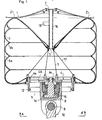
- the coupling device shown by way of example in FIGS. 1 and 2 is intended for coupling an envelope and an external element passing in the extension of the axis of this envelope. It applies in particular for the coupling of the polar zone of a space balloon envelope of generally cylindrical shape and an external element passing in the extension of the longitudinal axis of this balloon.
- This balloon as for example described in the patent FR filed under No. 84.18798, consists in particular of an outer casing 1 made by means of a composite material comprising a longitudinal chain of high resistance, of the "Kevlar" type.
- the gathered ends of this envelope are hung on pole pieces 2, such as for example described in the French patent application recently filed under No. 85.05674 in the name of the applicant, located in the axis of this envelope and able to take up significant efforts.
- the coupling device comprises a balloon 3 produced by means of an envelope having a cylindrical portion which is extended by gathered pleated portions whose edges are attached to pole pieces 4 and 5 arranged at the poles, lower and upper, of the 'envelope on the axis thereof.
- the material of the envelope of the balloon 3 is an airtight composite material having a longitudinal chain based on "Kevlar".
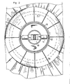
- this envelope is surrounded by a network of longitudinal reinforcements such as 6a located in meridian planes distributed around the envelope and by a network of circumferential reinforcements such as 6b extending transversely along this envelope.
- the longitudinal reinforcements 6a are fixed at the poles of the balloon on the pole pieces 4 and 5, while the circumferential reinforcements 6b are fixed on the envelope of the balloon 3 so that for the inflated state of said balloon, each reinforcement is in contact with the envelope around its entire periphery.
- a bundle of interpolar cables such as 7 arranged inside the envelope in the axis thereof.
- the pole pieces 4 and 5 of annular shape define the upper and lower poles of the balloon and have diameters of different lengths.
- the pole piece with a larger diameter 4 is constituted by an annular rim 4a provided with a groove intended to serve as a housing for blocking the ends of the envelope on its external peripheral face.
- This rim 4a is stiffened in its transverse plane by at least one rigid disc 4b connecting the central core 4c of this pole piece to its periphery 4a.
- this pole piece 4 is integral with drive means intended to drive the balloon in rotation.
- These drive means comprise an assembly 8 fixed relative to the balloon and connected via a hinge pin 9 to a shaft 10 secured to an element external to the balloon 3.
- On this assembly 8 are arranged two motors of entrainment such as 11 which actuate the rotation, about a radial axis perpendicular to the longitudinal axis of the balloon, of two pinions such as 12.
- These pinions 12 are arranged to cooperate with a toothed wheel 13 integral with the rim 4a of the pole piece 4 in order to center this piece in rotation about the longitudinal axis of the balloon.
- the diameter of the pole piece 4 approximately between one third and three-quarters of the diameter of the cross section delimited by the balloon sheath allows, during the rotational training of this balloon to interest all or a large part of the envelope of said balloon and create a lever arm important allowing the transmission of high torques.
- the assembly 8 is in contact by means of thrust bearings 14 with an assembly member 15 mechanically connected to the central core 4c of the pole piece 4 and can therefore thus allow the transmission of transverse forces to the balloon.
- the pole piece 5 of smaller diameter consists of an annular piece as described in the French patent application filed under No. 85.05674 in the name of the applicant.
- This pole piece is integral with a coupling member 16 made of a flexible material of high tensile strength and the other end of which is intended to be fixed to the pole piece 2 of a balloon of large volume such as we we will see it below.
- This coupling member can, for example, consist of a network of cables made of a material of the "Kevlar" type.
- This pole piece 5 is connected to the rim 4a of the pole piece 4 by a network of cables 17 of high tensile strength of the "Kevlar" type. These cables make it possible to ensure stable positioning of the pole piece 4, in particular avoiding the inclination of this piece 4 during the transmission of transverse forces to the balloon 3. This inclination would indeed cause overvoltages in the envelope of the balloon at level of its attachment to the pole piece 4, which could cause deterioration of said balloon.
- the pole piece 5 is, finally, provided with means for admission and rejection of air into the balloon 3.
- These means can be produced by any means known in the prior art. They can for example consist of a 3-way valve which would allow either to evacuate air or to admit air coming from a turbo-compressor or any other equivalent means.
- the balloon as described above, is initially inflated, without relative overpressure with a gas lighter than air, for example helium, in order to make it self-supporting, then brought to its fullness state by admission of 'air.
- This balloon is then positioned using a tripod system or any other known means with respect to the polar region of a large aerostatic balloon, then connected to the polar part 2 of this balloon via the body d 'coupling 16. In this position, the bottom of the balloon is in contact with the polar region of the envelope 1 of the balloon. It should be noted that this contact surface Zl is located in the gathered and therefore the most resistant part of the envelope.
- the identification of the contact between the balloon and the balloon at the level of the contact surface Z1 is carried out by means of an additional admission of air into the balloon.
- the balloon comprises means 19 for measuring the tensile force exerted in the coupling member 16. In fact, this force which tends to uncoupling the envelopes is a direct function of the reaction exerted on the contact surface Z1 and, consequently, of the relative internal overpressure of the balloon. These measurement means therefore control the means for admitting and rejecting air from the balloon in order to obtain an appropriate contact for the force to be transmitted to the envelope.
- the aerostatic balloon coupled to the balloon intended to allow aerostatic piloting by variation of gas masses, the relative interior overpressure and the shape of this balloon are therefore variable.
- the control of the internal overpressure of the balloon is ensured as a function of a reference value of the tensile force exerted in the coupling member 16.
- This value of reference is determined as a function of various parameters relating to the forces to be transmitted to the envelope, to the internal relative pressures of the balloon and of the envelope ...
- This coupling between an aerostatic balloon and a balloon. 3 capable of playing a damper role therefore allows the transmission of forces or significant torques between an external element and an aerostatic balloon, without risk of deterioration of said balloon.
- the diameter of the cross section of the balloon approximately between a quarter and a third of the diameter of the cross section of the ball, allows the transmission of these forces at a contact surface remote from the longitudinal axis of the ball .
- These forces, torque or transverse force are therefore transmitted with a large lever arm which causes a distribution of the stresses in all or a large part of the envelope of the balloon.
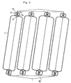
- This coupling balloon can be used to couple an aerostatic balloon to any means of traction allowing its horizontal winching. It can also allow the mooring of aerostatic balloons on structures, lower and upper, with a view to producing, by combination of balloon / balloon assemblies, aerostatic airships as shown in FIG. 3.
Landscapes
- Engineering & Computer Science (AREA)
- Mechanical Engineering (AREA)
- Aviation & Aerospace Engineering (AREA)
- Toys (AREA)
- Pivots And Pivotal Connections (AREA)
Applications Claiming Priority (2)
| Application Number | Priority Date | Filing Date | Title |
|---|---|---|---|
| FR8506465A FR2581022B1 (fr) | 1985-04-25 | 1985-04-25 | Dispositif pour l'accouplement d'une enveloppe avec un element externe a l'enveloppe |
| FR8506465 | 1985-04-25 |
Publications (3)
| Publication Number | Publication Date |
|---|---|
| EP0200244A2 true EP0200244A2 (de) | 1986-11-05 |
| EP0200244A3 EP0200244A3 (en) | 1987-10-28 |
| EP0200244B1 EP0200244B1 (de) | 1989-07-19 |
Family
ID=9318762
Family Applications (1)
| Application Number | Title | Priority Date | Filing Date |
|---|---|---|---|
| EP86200513A Expired EP0200244B1 (de) | 1985-04-25 | 1986-03-27 | Kupplungsvorrichtung für eine Umhüllung und einen Bestandteil ausserhalb dieser Umhüllung |
Country Status (5)
| Country | Link |
|---|---|
| US (1) | US4696444A (de) |
| EP (1) | EP0200244B1 (de) |
| CA (1) | CA1264700A (de) |
| DE (1) | DE3664443D1 (de) |
| FR (1) | FR2581022B1 (de) |
Cited By (1)
| Publication number | Priority date | Publication date | Assignee | Title |
|---|---|---|---|---|
| FR2669602A1 (fr) * | 1990-11-22 | 1992-05-29 | R P Dev Sarl | Aerostat comprenant au moins un ballon cylindrique a geometrie variable. |
Families Citing this family (10)
| Publication number | Priority date | Publication date | Assignee | Title |
|---|---|---|---|---|
| EP0616737A4 (de) * | 1991-11-29 | 1994-12-21 | Motorola Inc | Batterie mit schutzschaltung. |
| FR2790441B1 (fr) | 1999-03-02 | 2001-06-01 | Regipa And Partners Dev | Ensemble aerostatique comprenant une pluralite de ballons pressurises |
| AU2000274254A1 (en) | 2000-10-03 | 2002-04-15 | Interactive Star | Aerostatic assembly comprising a plurality of pressurised balloons |
| US9611024B2 (en) | 2011-08-03 | 2017-04-04 | Lockheed Martin Corporation | Ballonet measurement system |
| US9845141B2 (en) | 2012-12-07 | 2017-12-19 | Raven Industries, Inc. | Atmospheric balloon system |
| US9327817B1 (en) | 2014-02-03 | 2016-05-03 | Google Inc. | Ballonet for a balloon |
| US20160221661A1 (en) | 2015-02-02 | 2016-08-04 | Derek Lee Bohannon | Tendon sleeve for high-altitude balloon and system for making the same |
| US10780997B1 (en) * | 2018-07-09 | 2020-09-22 | National Technology & Engineering Solutions Of Sandia, Llc | Systems and methods for shock-resistant memory devices |
| US11433984B2 (en) | 2019-04-19 | 2022-09-06 | Lockheed Martin Corporation | Ballonet measurement systems and methods |
| FR3107253B1 (fr) * | 2020-02-18 | 2022-05-20 | Taupin Sebastien | Système aérien de transport et de livraison de colis sans pilote humain embarqué, procédé logistique mis en œuvre dans ce système et dispositif aérostatique intégré dans ce système |
Family Cites Families (11)
| Publication number | Priority date | Publication date | Assignee | Title |
|---|---|---|---|---|
| US1320867A (en) * | 1919-11-04 | kehler | ||
| US37667A (en) * | 1863-02-10 | Improvement in balloons | ||
| US1430393A (en) * | 1921-03-05 | 1922-09-26 | Lynde Carleton John | Dirigible |
| US1609521A (en) * | 1925-10-29 | 1926-12-07 | Goodyear Tire & Rubber | Combined air scoop and damper valve |
| US2008552A (en) * | 1933-03-17 | 1935-07-16 | Oak Rubber Company | Attaching means for inflatable articles |
| US2919083A (en) * | 1956-03-12 | 1959-12-29 | Winzen Res Inc | Balloon structure and method of launching the same |
| US2990147A (en) * | 1956-03-21 | 1961-06-27 | Gen Mills Inc | Balloon load attachment fitting |
| US3069114A (en) * | 1961-06-26 | 1962-12-18 | Raymond W Maas | Balloon gondola orienter |
| US3218756A (en) * | 1964-02-20 | 1965-11-23 | Dragich Nicholas | Connecting frame for multi-staged inflated toy rocket assembly |
| US3276726A (en) * | 1965-07-16 | 1966-10-04 | James E Webb | Inflation system for balloon type satellites |
| DE1481222C3 (de) * | 1966-04-09 | 1975-01-23 | Hermann 7742 St. Georgen Papst | Motorgetriebenes, lenkbares Luftschiff mit Doppelwandhülle |
-
1985
- 1985-04-25 FR FR8506465A patent/FR2581022B1/fr not_active Expired
-
1986
- 1986-03-27 EP EP86200513A patent/EP0200244B1/de not_active Expired
- 1986-03-27 DE DE8686200513T patent/DE3664443D1/de not_active Expired
- 1986-04-07 CA CA000505972A patent/CA1264700A/fr not_active Expired - Lifetime
- 1986-04-18 US US06/853,446 patent/US4696444A/en not_active Expired - Fee Related
Cited By (1)
| Publication number | Priority date | Publication date | Assignee | Title |
|---|---|---|---|---|
| FR2669602A1 (fr) * | 1990-11-22 | 1992-05-29 | R P Dev Sarl | Aerostat comprenant au moins un ballon cylindrique a geometrie variable. |
Also Published As
| Publication number | Publication date |
|---|---|
| EP0200244A3 (en) | 1987-10-28 |
| US4696444A (en) | 1987-09-29 |
| CA1264700A (fr) | 1990-01-23 |
| EP0200244B1 (de) | 1989-07-19 |
| FR2581022B1 (fr) | 1987-11-20 |
| FR2581022A1 (fr) | 1986-10-31 |
| DE3664443D1 (en) | 1989-08-24 |
Similar Documents
| Publication | Publication Date | Title |
|---|---|---|
| EP0184262B1 (de) | Steuerbarer aerostatischer Ballon | |
| EP0200244B1 (de) | Kupplungsvorrichtung für eine Umhüllung und einen Bestandteil ausserhalb dieser Umhüllung | |
| EP1255673B1 (de) | Rpv, insbesondere zur überwachung oder untersuchung | |
| EP0021901B1 (de) | Kompakt-Gelenkrotor für Drehflüger | |
| EP1346910A1 (de) | Homokinetisch angetriebener Rotor für ein Drehflügelflugzeug | |
| EP2996937B1 (de) | Drohne für grosse höhen | |
| EP0289374B1 (de) | Kombinierte Lagervorrichtung eines Drehflügelflugzeugrotors und damit ausgerüsteter Rotor | |
| EP1019287A1 (de) | Luftfahrzeug | |
| WO2010092253A1 (fr) | Ameliorations aux aerodynes captifs | |
| FR2972706A1 (fr) | Aerostat dirigeable a profil variable commande | |
| EP1242279B1 (de) | Kleingebautes funkgesteuertes luftfahrzeug | |
| FR2801034A1 (fr) | Helicoptere a pilotage pendulaire a haute stabilite et a grande manoeuvrabilite | |
| CA2733314C (fr) | Amortisseur d'une pale, et rotor muni d'un tel amortisseur | |
| FR2941921A1 (fr) | Aerodyne captif et son procede de recuperation | |
| EP0033020A1 (de) | Verfahren und Vorrichtung zum Starten und Aufblasen eines Raumfahrballons | |
| EP1427632B1 (de) | Fesselballon und zugehörige steuereinrichtung | |
| FR2669602A1 (fr) | Aerostat comprenant au moins un ballon cylindrique a geometrie variable. | |
| FR2541732A1 (fr) | Moteur anemodynamique compound avec ses applications a la propulsion | |
| FR2941920A1 (fr) | Systeme et procede de controle de la position d'un aerodyne captif | |
| FR2898581A1 (fr) | Pale comportant une manchette integree et rotor de giravion pourvu d'une telle pale. | |
| WO2018015647A1 (fr) | Pale destinée a être montée sur une éolienne comportant une voilure tournant autour d'une poutre glissée a l'intérieur | |
| FR2851224A1 (fr) | Aeronefs hybrides, comportant un systeme d'allegement torique et une voilure tournante centrale | |
| EP4178854A1 (de) | Ferngesteuertes unbemanntes luftfahrzeug mit einer aufblasbaren struktur | |
| EP4054931A1 (de) | Angebundener ballon mit niveaulage | |
| FR2552395A1 (fr) | Perfectionnements apportes aux helices sustentatrices pour aeronefs |
Legal Events
| Date | Code | Title | Description |
|---|---|---|---|
| PUAI | Public reference made under article 153(3) epc to a published international application that has entered the european phase |
Free format text: ORIGINAL CODE: 0009012 |
|
| AK | Designated contracting states |
Kind code of ref document: A2 Designated state(s): BE CH DE FR GB IT LI LU NL |
|
| PUAL | Search report despatched |
Free format text: ORIGINAL CODE: 0009013 |
|
| AK | Designated contracting states |
Kind code of ref document: A3 Designated state(s): BE CH DE FR GB IT LI LU NL |
|
| 17P | Request for examination filed |
Effective date: 19871202 |
|
| 17Q | First examination report despatched |
Effective date: 19880907 |
|
| GRAA | (expected) grant |
Free format text: ORIGINAL CODE: 0009210 |
|
| AK | Designated contracting states |
Kind code of ref document: B1 Designated state(s): BE CH DE FR GB IT LI LU NL |
|
| REF | Corresponds to: |
Ref document number: 3664443 Country of ref document: DE Date of ref document: 19890824 |
|
| ITF | It: translation for a ep patent filed | ||
| GBT | Gb: translation of ep patent filed (gb section 77(6)(a)/1977) | ||
| PLBE | No opposition filed within time limit |
Free format text: ORIGINAL CODE: 0009261 |
|
| STAA | Information on the status of an ep patent application or granted ep patent |
Free format text: STATUS: NO OPPOSITION FILED WITHIN TIME LIMIT |
|
| 26N | No opposition filed | ||
| ITTA | It: last paid annual fee | ||
| EPTA | Lu: last paid annual fee | ||
| PGFP | Annual fee paid to national office [announced via postgrant information from national office to epo] |
Ref country code: LU Payment date: 19960301 Year of fee payment: 11 |
|
| PGFP | Annual fee paid to national office [announced via postgrant information from national office to epo] |
Ref country code: BE Payment date: 19960313 Year of fee payment: 11 |
|
| PGFP | Annual fee paid to national office [announced via postgrant information from national office to epo] |
Ref country code: GB Payment date: 19960326 Year of fee payment: 11 Ref country code: FR Payment date: 19960326 Year of fee payment: 11 |
|
| PGFP | Annual fee paid to national office [announced via postgrant information from national office to epo] |
Ref country code: NL Payment date: 19960328 Year of fee payment: 11 |
|
| PGFP | Annual fee paid to national office [announced via postgrant information from national office to epo] |
Ref country code: CH Payment date: 19960409 Year of fee payment: 11 |
|
| PGFP | Annual fee paid to national office [announced via postgrant information from national office to epo] |
Ref country code: DE Payment date: 19960525 Year of fee payment: 11 |
|
| PG25 | Lapsed in a contracting state [announced via postgrant information from national office to epo] |
Ref country code: LU Free format text: LAPSE BECAUSE OF NON-PAYMENT OF DUE FEES Effective date: 19970327 Ref country code: GB Effective date: 19970327 |
|
| PG25 | Lapsed in a contracting state [announced via postgrant information from national office to epo] |
Ref country code: LI Effective date: 19970331 Ref country code: CH Effective date: 19970331 Ref country code: BE Effective date: 19970331 |
|
| BERE | Be: lapsed |
Owner name: CENTRE NATIONAL D'ETUDES SPATIALES CNES ETABLISSE Effective date: 19970331 |
|
| PG25 | Lapsed in a contracting state [announced via postgrant information from national office to epo] |
Ref country code: NL Effective date: 19971001 |
|
| REG | Reference to a national code |
Ref country code: CH Ref legal event code: PL |
|
| GBPC | Gb: european patent ceased through non-payment of renewal fee |
Effective date: 19970327 |
|
| PG25 | Lapsed in a contracting state [announced via postgrant information from national office to epo] |
Ref country code: FR Free format text: LAPSE BECAUSE OF NON-PAYMENT OF DUE FEES Effective date: 19971128 |
|
| NLV4 | Nl: lapsed or anulled due to non-payment of the annual fee |
Effective date: 19971001 |
|
| PG25 | Lapsed in a contracting state [announced via postgrant information from national office to epo] |
Ref country code: DE Effective date: 19971202 |
|
| REG | Reference to a national code |
Ref country code: FR Ref legal event code: ST |
|
| PG25 | Lapsed in a contracting state [announced via postgrant information from national office to epo] |
Ref country code: IT Free format text: LAPSE BECAUSE OF NON-PAYMENT OF DUE FEES Effective date: 20050327 |