EP0200014B2 - Process for the break-proof contacting of varnish-insulated wires - Google Patents
Process for the break-proof contacting of varnish-insulated wires Download PDFInfo
- Publication number
- EP0200014B2 EP0200014B2 EP86104429A EP86104429A EP0200014B2 EP 0200014 B2 EP0200014 B2 EP 0200014B2 EP 86104429 A EP86104429 A EP 86104429A EP 86104429 A EP86104429 A EP 86104429A EP 0200014 B2 EP0200014 B2 EP 0200014B2
- Authority
- EP
- European Patent Office
- Prior art keywords
- wire
- break
- welding
- wires
- varnish
- Prior art date
- Legal status (The legal status is an assumption and is not a legal conclusion. Google has not performed a legal analysis and makes no representation as to the accuracy of the status listed.)
- Expired - Lifetime
Links
- 238000000034 method Methods 0.000 title claims description 11
- 238000003466 welding Methods 0.000 claims description 22
- 239000000853 adhesive Substances 0.000 claims description 13
- 230000001070 adhesive effect Effects 0.000 claims description 13
- 238000004804 winding Methods 0.000 claims description 6
- 239000000919 ceramic Substances 0.000 claims description 3
- 229920003023 plastic Polymers 0.000 claims description 3
- 239000004033 plastic Substances 0.000 claims description 3
- 230000009974 thixotropic effect Effects 0.000 claims description 2
- 238000002604 ultrasonography Methods 0.000 description 7
- 238000004519 manufacturing process Methods 0.000 description 6
- 238000005476 soldering Methods 0.000 description 6
- 238000009413 insulation Methods 0.000 description 4
- 239000010410 layer Substances 0.000 description 4
- 230000000694 effects Effects 0.000 description 3
- 239000004922 lacquer Substances 0.000 description 2
- 229910000859 α-Fe Inorganic materials 0.000 description 2
- 208000000260 Warts Diseases 0.000 description 1
- 238000000576 coating method Methods 0.000 description 1
- 230000006698 induction Effects 0.000 description 1
- 239000011810 insulating material Substances 0.000 description 1
- 239000000463 material Substances 0.000 description 1
- 238000005259 measurement Methods 0.000 description 1
- 230000036278 prepulse Effects 0.000 description 1
- 238000003825 pressing Methods 0.000 description 1
- 230000005855 radiation Effects 0.000 description 1
- 238000010008 shearing Methods 0.000 description 1
- 239000002356 single layer Substances 0.000 description 1
- 201000010153 skin papilloma Diseases 0.000 description 1
- 229910000679 solder Inorganic materials 0.000 description 1
- 239000000126 substance Substances 0.000 description 1
- 239000000758 substrate Substances 0.000 description 1
Images
Classifications
-
- H—ELECTRICITY
- H01—ELECTRIC ELEMENTS
- H01F—MAGNETS; INDUCTANCES; TRANSFORMERS; SELECTION OF MATERIALS FOR THEIR MAGNETIC PROPERTIES
- H01F41/00—Apparatus or processes specially adapted for manufacturing or assembling magnets, inductances or transformers; Apparatus or processes specially adapted for manufacturing materials characterised by their magnetic properties
- H01F41/02—Apparatus or processes specially adapted for manufacturing or assembling magnets, inductances or transformers; Apparatus or processes specially adapted for manufacturing materials characterised by their magnetic properties for manufacturing cores, coils, or magnets
- H01F41/04—Apparatus or processes specially adapted for manufacturing or assembling magnets, inductances or transformers; Apparatus or processes specially adapted for manufacturing materials characterised by their magnetic properties for manufacturing cores, coils, or magnets for manufacturing coils
- H01F41/10—Connecting leads to windings
-
- H—ELECTRICITY
- H01—ELECTRIC ELEMENTS
- H01R—ELECTRICALLY-CONDUCTIVE CONNECTIONS; STRUCTURAL ASSOCIATIONS OF A PLURALITY OF MUTUALLY-INSULATED ELECTRICAL CONNECTING ELEMENTS; COUPLING DEVICES; CURRENT COLLECTORS
- H01R4/00—Electrically-conductive connections between two or more conductive members in direct contact, i.e. touching one another; Means for effecting or maintaining such contact; Electrically-conductive connections having two or more spaced connecting locations for conductors and using contact members penetrating insulation
- H01R4/02—Soldered or welded connections
- H01R4/026—Soldered or welded connections comprising means for eliminating an insulative layer prior to soldering or welding
-
- H—ELECTRICITY
- H01—ELECTRIC ELEMENTS
- H01R—ELECTRICALLY-CONDUCTIVE CONNECTIONS; STRUCTURAL ASSOCIATIONS OF A PLURALITY OF MUTUALLY-INSULATED ELECTRICAL CONNECTING ELEMENTS; COUPLING DEVICES; CURRENT COLLECTORS
- H01R43/00—Apparatus or processes specially adapted for manufacturing, assembling, maintaining, or repairing of line connectors or current collectors or for joining electric conductors
- H01R43/02—Apparatus or processes specially adapted for manufacturing, assembling, maintaining, or repairing of line connectors or current collectors or for joining electric conductors for soldered or welded connections
- H01R43/0207—Ultrasonic-, H.F.-, cold- or impact welding
Definitions
- the invention relates to a contacting method of enamelled wire with a diameter of less than 100 microns on vertically aligned parts of plate-shaped terminal lugs in wire-wound ceramic, plastic or ferrite cores, which are designed as choke chips.
- the induction coils used are becoming smaller and smaller as the miniaturization progresses. This means that the winding wires used have an ever smaller diameter, which makes contacting the coil connections more difficult.
- the enamel-insulated coil connections can have a diameter in the range from 30 to 100 ⁇ m (0.03 - 0.1 mm).
- such a miniaturized HF choke in chip design is proposed, in which one or more layers of coated, insulated wire must be contacted on plate-shaped contact elements.
- lacquer-insulated coil connections have been contacted by manual, mechanized or even fully automated soldering. Temperatures of approx. 500 ° C are necessary especially for soldering such high temperature resistant enamelled wires. The heat radiation can damage the materials in the immediate soldering area.
- Ultrasonic welding can advantageously be used for contacting, the lacquer insulation layer being equally broken up and the welding effect being achieved due to the mechanical effect of the ultrasound.
- problems arise with diameters of enamelled wires less than 0.4 mm, since the wire weakens at the connection point due to the deformation. Since the mechanical requirements cannot generally be maintained, an additional cover plate has to be welded on to improve the mechanical strength. The latter is described specifically for laser welding in DE-OS 33 07 773. In the manufacture of RF choke coils, which are either manufactured with connecting wire or more recently with connecting lugs as so-called RF choke chips, this would mean an additional effort, since the cover plates have to be fed in before welding.
- a so-called socket strip for electrical connectors of ribbon cables is known, in which the ends of the wires of the ribbon cable are connected to the respective contact springs by ultrasonic welding.
- the individual wires of the ribbon cable should be able to be brought to the contact springs without being stripped and welded through the insulation.
- the insulated cable end is placed in a trough-shaped bed and the insulating material is squeezed away by the rubbing process caused by ultrasound.
- DE-A-27 57 038 specifies the ultrasonic soldering of such lines, in which the wire end is provided beforehand with a metallic solder.
- the object of the invention is to create a contacting method suitable for microinductivities.
- the object is achieved in a method of the type mentioned with the features a) to c) of the claim. This method makes it possible to contact microinductivities in an integrated manufacturing process.
- the advantages of ultrasonic welding of enamelled wires such as reliable contacting and the low temperature load, are used and the previous disadvantage of low strength is also compensated for by the application of the adhesive.
- Such adhesives are easy to handle and can be applied as drops to the weld. After curing, the adhesive is mechanically strong and in particular also resistant to changes in temperature. The volume of the drop of adhesive can be selected so that the entire deformation site is enclosed. As a result, the strength of the contact is greater than the wire strength
- 1 means a metallic base, for example a contact element, on which a paint-insulated wire 2 is to be contacted.
- Ultrasound welding can advantageously be used for this purpose, for which an ultrasound sonotrode with 10 and associated ultrasound anvil with 11 are indicated.
- the insulation layers are broken up by the mechanical effect and the metallic parts are contacted by friction welding with simultaneous deformation.
- a one-component adhesive is used as the adhesive. It is important for the intended use that the adhesive substance is thixotropic, i.e. dimensionally stable, is and hardens quickly. In automated production, a drop of the adhesive can then be applied to the welding point directly after welding, which hardens after passing through UV light after a few seconds, so that a shape 4 results which surrounds the deformed area of the wire 1.
- an RF choke is designated 20.
- Such chokes usually consist of a core 21, which can be made of ceramic, plastic or ferrite, with a single-layer or multi-layer winding 24 made of enamelled, insulated round wire.
- a core 21 which can be made of ceramic, plastic or ferrite, with a single-layer or multi-layer winding 24 made of enamelled, insulated round wire.
- the core 21 has end faces 22 with recesses 23, into which connection tabs 25 with a platelet surface are introduced on the front and rear sides.
- the connecting lugs 25 are bent at their free part so that they can be plugged onto printed circuit boards or the like.
- connection lug 25 must be contacted with the winding wire 24:
- the winding wire 24 is placed diagonally around the connection lug 25 and the end 26 of the winding wire 24 is welded on using ultrasound in the manner described above.
- a drop of the specified adhesive is then applied to the surface of the connecting lug 25.
- An approximately wart-shaped area 27 is formed, which covers the entire deformation area of the ultrasonic welding. After the adhesive has hardened, a mechanically stable connection is achieved.
- weld is also protected against climatic and corrosive influences.
Landscapes
- Engineering & Computer Science (AREA)
- Power Engineering (AREA)
- Manufacturing & Machinery (AREA)
- Manufacturing Cores, Coils, And Magnets (AREA)
- Manufacturing Of Electrical Connectors (AREA)
- Coils Or Transformers For Communication (AREA)
- Connections Effected By Soldering, Adhesion, Or Permanent Deformation (AREA)
Description
Die Erfindung bezieht sich auf ein Kontaktierungsverfahren von lackisolierten Wickeldrähten mit Durchmesser unter 100 µm auf vertikal ausgerichteten Teilen von plättchenförmigen Anschlußfahnen bei drahtbewickelten Keramik-, Kunststoff- oder Ferritkernen, die als Drossel-Chips ausgebildet sind.The invention relates to a contacting method of enamelled wire with a diameter of less than 100 microns on vertically aligned parts of plate-shaped terminal lugs in wire-wound ceramic, plastic or ferrite cores, which are designed as choke chips.
Bei elektrischen Komponenten, wie z.B. bei Relais, Schützen und anderen Bauelementen, werden im Rahmen einer fortschreitenden Miniaturisierung die verwendeten Induktionsspulen immer kleiner. Dies bedeutet, daß die dabei eingesetzten Wikkeldrähte einen immer geringeren Durchmesser haben, wodurch das Kontaktieren der Spulenanschlüsse schwieriger wird. Beispielsweise können die lackisolierten Spulenanschlüsse einen Durchmesser im Bereich von 30 bis 100 µm (0,03 - 0,1 mm) aufweisen. In der älteren deutschen Patentanmeldung P 34 33 692.3 wird eine derartige miniaturisierte HF-Drossel in Chip-Bauweise vorgeschlagen, bei der ein-oder mehrlagig gewickelter, lackisolierter Draht an plättchenförmige Kontaktelemente kontaktiert werden muß.For electrical components such as in the case of relays, contactors and other components, the induction coils used are becoming smaller and smaller as the miniaturization progresses. This means that the winding wires used have an ever smaller diameter, which makes contacting the coil connections more difficult. For example, the enamel-insulated coil connections can have a diameter in the range from 30 to 100 µm (0.03 - 0.1 mm). In the older German patent application P 34 33 692.3, such a miniaturized HF choke in chip design is proposed, in which one or more layers of coated, insulated wire must be contacted on plate-shaped contact elements.
Bisher werden lackisolierte Spulenanschlüsse durch manuelles, mechanisiertes oder auch vollautomatisiertes Löten kontaktiert. Speziell für das Verlöten derartiger hochtemperaturfester Lackdrähte sind dabei Temperaturen von ca. 500 °C notwendig. Durch die Wärmestrahlung können die im unmittelbaren Lötbereich liegenden Werkstoffe geschädigt werden.Until now, lacquer-insulated coil connections have been contacted by manual, mechanized or even fully automated soldering. Temperatures of approx. 500 ° C are necessary especially for soldering such high temperature resistant enamelled wires. The heat radiation can damage the materials in the immediate soldering area.
Zum Kontaktieren kann vorteilhaft das Ultraschallschweißen eingesetzt werden, wobei durch die mechanische Wirkung des Ultraschalls gleichermaßen die Lackisolationsschicht aufgebrochen und die Verschweißwirkung erreicht werden. Allerdings treten bei Durchmessern von lackisolierten Drähten unter 0,4 mm Probleme auf, da beim Anschweißen der Draht an der Verbindungsstelle durch die Verformung geschwächt wird. Da die gestellten mechanischen Forderungen im allgemeinen nicht aufrechterhalten werden können, muß bisher zur Verbesserung der mechanischen Festigkeit ein zusätzliches Deckplättchen mit aufgeschweißt werden. Letzteres wird speziell für das Laserschweißen in der DE-OS 33 07 773 beschrieben. Bei der Fertigung von HF-Drosselspulen, die entweder mit Anschlußdraht oder auch neuerdings mit Anschlußfahnen als sogenannte HF-Drossel-Chips hergestellt werden, würde dies einen Mehraufwand bedeuten, da die Deckplättchen vor dem Verschweißen zugeführt werden müssen.Ultrasonic welding can advantageously be used for contacting, the lacquer insulation layer being equally broken up and the welding effect being achieved due to the mechanical effect of the ultrasound. However, problems arise with diameters of enamelled wires less than 0.4 mm, since the wire weakens at the connection point due to the deformation. Since the mechanical requirements cannot generally be maintained, an additional cover plate has to be welded on to improve the mechanical strength. The latter is described specifically for laser welding in DE-OS 33 07 773. In the manufacture of RF choke coils, which are either manufactured with connecting wire or more recently with connecting lugs as so-called RF choke chips, this would mean an additional effort, since the cover plates have to be fed in before welding.
Speziell aus der DE-A-27 28 914 ist eine sogenannte Buchsenleiste für elektrische Steckverbinder von Flachbandkabeln bekannt, bei der die Enden der Adern des Flachbandkabels mit den jeweiligen Kontaktfedem durch Ultraschallschweißung verbunden sind. Dabei sollen die einzelnen Adern des Flachbandkabels unabisoliert an die Kontaktfedem herangeführt und durch die Isolierung hindurch verschweißt werden können. Im einzelnen wird das isolierte Leitungsende in ein rinnenartig gebogenes Bett gelegt und durch den bei Ultraschalleinwirkung erfolgenden Reibvorgang das Isoliermaterial weggequetscht. Als Alternative zum Ultraschallschweißen ist in der DE-A-27 57 038 das Ultraschallöten derartiger Leitungen angegeben, bei dem das Drahtende vorab mit einem metallischen Lötmittel versehen wird.From DE-A-27 28 914 a so-called socket strip for electrical connectors of ribbon cables is known, in which the ends of the wires of the ribbon cable are connected to the respective contact springs by ultrasonic welding. The individual wires of the ribbon cable should be able to be brought to the contact springs without being stripped and welded through the insulation. Specifically, the insulated cable end is placed in a trough-shaped bed and the insulating material is squeezed away by the rubbing process caused by ultrasound. As an alternative to ultrasonic welding, DE-A-27 57 038 specifies the ultrasonic soldering of such lines, in which the wire end is provided beforehand with a metallic solder.
Weiterhin sind unterschiedlich aufgebaute Kontaktierungen von Drähten mit elektrischen Anschlußelementen aus der DE-C-11 94 945, der DE-A-19 03 006 und der GB-A-21 02 632 bekannt. Bei diesen Kontaktierungen werden durchweg spezifische Lötverfahren angewandt.Furthermore, differently structured contacts of wires with electrical connection elements are known from DE-C-11 94 945, DE-A-19 03 006 and GB-A-21 02 632. Specific soldering methods are used throughout these contacts.
Lötverfahren sind aber für mit hochwarmfestem Lack isolierte Drähte ungeeignet. Speziell das Ultraschallschweißen wird dann problematisch, wenn der zu kontaktierende Draht einen bestimmten Querschnitt unterschreitet und keine konkav ge- wölbte Aufnahme vorhanden ist. In der US-A-38 22 465 wird hierzu ausgeführt, daß dünne lackisolierte Drähte nur dann erfolgreich durch Ultraschall auf metallische Unterlagen aufgeschweißt werden können, wenn der Schweißzyklus aus einem Vorimpuls zum Entfernen der Isolierung und den eigentlichen Schweißimpuls zum Herstellen der metallischen Verbindung besteht. Es wird dort speziell in Teilschritten mit variierenden Anpreßkräften und Ultraschallamplituden gearbeitet, was jedoch nicht ohne weiteres in einer automatischen Fertigung für die Massenproduktion von insbesondere elektronischen Bauteilen einsetzbar ist. In der Praxis kann nur ein vergleichsweise unspezifischer Schweißimpuls abgegeben werden.However, soldering methods are unsuitable for wires insulated with high-temperature resistant lacquer. Ultrasonic welding in particular becomes problematic when the wire to be contacted falls below a certain cross-section and there is no concavely curved receptacle. In US-A-38 22 465 it is stated that thin enamelled wires can only be successfully ultrasonically welded onto metallic substrates if the welding cycle consists of a pre-pulse to remove the insulation and the actual welding pulse to produce the metallic connection. There, it is worked in particular in partial steps with varying contact forces and ultrasonic amplitudes, which, however, cannot easily be used in an automatic production for the mass production of electronic components in particular. In practice, only a comparatively unspecific welding pulse can be given.
Aufgabe der Erfindung ist es demgegenüber, ein für Mikroinduktivitäten geeignetes Kontaktierungsverfahren zu schaffen.In contrast, the object of the invention is to create a contacting method suitable for microinductivities.
Die Aufgabe ist erfindungsgemäß bei einem Verfahren der eingangs genannten Art mit den Merkmalen a) bis c) des Patentanspruches gelöst. Mit diesem Verfahren ist die Kontaktierung von Mikroinduktivitäten in einem integrierten Fertigungsvorgang möglich.The object is achieved in a method of the type mentioned with the features a) to c) of the claim. This method makes it possible to contact microinductivities in an integrated manufacturing process.
Bei der Erfindung werden die Vorzüge des Ultraschallschweißens von Lackdrähten, wie sichere Kontaktierung und die geringe Temperaurbelastung, genutzt und gleichermaßen der bisherige Nachteil der geringen Festigkeit durch das Aufbringen des Klebemittels kompensiert. Solche Klebemittel sind einfach handhabbar und können als Tropfen auf die Schweißstelle aufgebracht werden. Nach dem Aushärten ist der Kleber mechanisch fest und insbesondere auch temperaturwechselbeständig. Das Volumen des Klebetropfens kann so gewähltwerden, daß die gesamte Verformungsstelle umschlossen wird. Im Ergebnis wird dadurch erreicht, daß die Festigkeit der Kontaktierung größer als die Drahtfestigkeit istIn the invention, the advantages of ultrasonic welding of enamelled wires, such as reliable contacting and the low temperature load, are used and the previous disadvantage of low strength is also compensated for by the application of the adhesive. Such adhesives are easy to handle and can be applied as drops to the weld. After curing, the adhesive is mechanically strong and in particular also resistant to changes in temperature. The volume of the drop of adhesive can be selected so that the entire deformation site is enclosed. As a result, the strength of the contact is greater than the wire strength
Bei der Verwendung des Verfahrens für elektronische Bauteile werden nicht nur die geforderte Verbesserung der mechanischen Stabilität bei gleichzeitiger Fertigungsvereinfachung erzielt; es wird auch erreicht, daß die Schweißstelle des Bauteiles gegen klimatische und korrosive Einflüsse ge- schützt ist. Die Schweißstelle oder das gesamte Bauteil kann darüber hinaus auch mit mechanisch festen Überzügen ummantelt werden.When using the method for electro African components not only achieve the required improvement in mechanical stability while simplifying production; it is also achieved that the welding point of the component is protected against climatic and corrosive influences. The weld or the entire component can also be covered with mechanically strong coatings.
Weitere Einzelheiten und Vorteile der Erfindung ergeben such aus nachfolgenden Figurenbeschreibung von Ausführungsbeispielen anhand der Zeichnung. Es zeigen
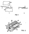
- FIG 1a) und b) das Prinzip des Kontaktierungsverfahrens.
- FIG 2 einen neuartigen HF-Drossel-Chip in perspektivischer Darstellung, bei dem die Erfindung verwendet ist und
- FIG 1a) and b) the principle of the contacting method.
- 2 shows a novel RF choke chip in perspective, in which the invention is used and
In FIG 1 bedeutet 1 eine metallische Unterlage, beispielsweise ein Kontaktelement, worauf ein lackisolierter Draht 2 kontaktiert werden werden soll. Dafür kann vorteilhaft das Ultraschallschweißen verwendet werden, wofür eine Ultraschallsonotrode mit 10 und zugehöriger Ultraschallamboß mit 11 angedeutet sind. Beim Ultraschallschweißen werden durch die mechanische Wirkung die Isolationsschichten aufgebrochen und durch Reibschweißung die metallischen Teile unter gleichzeitiger Verformung kontaktiert.In FIG. 1, 1 means a metallic base, for example a contact element, on which a paint-insulated
Problematisch ist allerdings das Ultraschallschweißen bei Drähten geringen Durchmesssers, insbesondere unter 0,4 mm, da es hier durch die Verformung zu einem Abscheren des Drahtes kommen kann. Wenn gemäß FIG 1 b nach dem Aufschweißen auf due Kontaktstelle ein Tropfen eines geeigneten Klebemittels aufgebracht wird, läßt sich der gesamte gegen Abscherung gefährdete Bereich schützen und somit eine sichere mechanische Verbindung erreichen.However, ultrasonic welding is problematic for wires of small diameter, in particular less than 0.4 mm, since the wire can shear due to the deformation. If, according to FIG. 1 b, a drop of a suitable adhesive is applied to the contact point after welding, the entire area at risk of shearing can be protected and a secure mechanical connection can thus be achieved.
Insbesondere für das Ultraschallschweißen von Drähten unter 100 µm Durchmesser ist es wichtig, durch den Andruck der Sonotrode 10 den Draht 1 vorab zu verformen und anschließend den Schall einwirken zu lassen. Dabei werden beispielweise mit einer Ultraschallfrequenz von 40 kHz und Andruckkräften zwischen 2 und 10 N gearbeitet, wobei die Leistungen üblicherweise im Bereich bis zu einigen Watt liegen.In particular for the ultrasonic welding of wires with a diameter of less than 100 μm, it is important to deform the wire 1 beforehand by pressing the
Als Klebemittel wird beispielsweise ein Einkomponenten klebstoff verwendet. Wichtig für den bestimmungsmäßigen Gebrauch ist dabei, daß die Klebesubstanz thixotrop, d.h. formbeständig, ist und schnell aushärtet. Bei einer automatisierten Fertigung kann dann unmittelbar nach der Schweißung ein Tropfen des Klebemittels punktuell auf die Schweißstelle aufgebracht werden, der bei Durchlauf durch UV-Licht nach wenigen Sekunden aushärtet, so daß sich eine Form 4 ergibt, die den verformten Bereich des Drahtes 1 umschließt.For example, a one-component adhesive is used as the adhesive. It is important for the intended use that the adhesive substance is thixotropic, i.e. dimensionally stable, is and hardens quickly. In automated production, a drop of the adhesive can then be applied to the welding point directly after welding, which hardens after passing through UV light after a few seconds, so that a shape 4 results which surrounds the deformed area of the wire 1.
In FIG 2 ist eine HF-Drossel mit 20 bezeichnet. Solche Drosseln bestehen üblicherweise aus einem Kern 21, der aus Keramik, Kunststoff oder Ferrit bestehen kann mit eine darauf befindlichen ein-oder mehrlagigen Wicklung 24 aus lackisoliertem Runddraht. Im Rahmen einer Miniaturisierung solcher elektronischer Bauteile (bspw. 3,2mm x 2,5mm x 1,5 mm und 40 wm-Draht für Nenninduktivitäten von 0,068 - 8,2 µH bei 2 MHz Meßfrequenz) ist man dazu übergegangen, statt der bisher üblichen Anschlußdrähte großflächige Kontaktelemente vorzusehen. Dazu weist der Kern 21 Stirnenden 22 mitAussparungen 23 auf, in den front- und rückseitig plättchenflächige Anschlußfahnen 25 eingebracht sind. An ihrem freien Teil sind die Anschlußfahnen 25 abgeknickt, so daß sie auf Leiterplatten od. dgl. gesteckt werden können.In FIG 2, an RF choke is designated 20. Such chokes usually consist of a
Die Anschlußfahne 25 muß mit dem Wickeldraht 24 kontaktiert werden: Hierzu wird der Wickeldraht 24 diagonal um die Anschlußfahne 25 gelegt und das Ende 26 des Wickeldrahtes 24 in oben beschriebener Weise mittels Ultraschall aufgeschweißt. Auf die Fläche der Anschlußfahne 25 wird anschließend ein Tropfen des angegebenen Klebers aufgebracht. Es bildet sich ein in etwa warzenförmiger Bereich 27, der den gesamten Verformungsbereich des Ultraschallschweißens überdeckt. Nach Aushärten des Klebers ist eine mechanisch stabile Verbindung erreicht.The
Es hat sich gezeigt, daß durch eine kombinierte Schweiß- und Klebverbindung von dünnen lackisolierten Drähten mit den Kontaktelementen bei den Bauteilen nach FIG 2 eine Festigkeit erreichtwird, die größer ist als die Drahtfestigkeit. Messungen des Übergangswiderstandes sowie Temperaturwechsel-und weitere elektrische Prüfungen ergaben hinreichend gute Werte.It has been shown that a combined weld and adhesive connection of thin enamel-insulated wires with the contact elements in the components according to FIG. 2 achieves a strength which is greater than the wire strength. Measurements of the contact resistance as well as temperature changes and other electrical tests gave sufficiently good values.
Vorteilhaft ist bei den vorstehend beschriebenen Beispielen weiterhin, daß die Schweißstelle auch gegen klimatische und korrosive Einflüsse geschützt ist.It is also advantageous in the examples described above that the weld is also protected against climatic and corrosive influences.
Claims (1)
Applications Claiming Priority (2)
| Application Number | Priority Date | Filing Date | Title |
|---|---|---|---|
| DE19853513435 DE3513435A1 (en) | 1985-04-15 | 1985-04-15 | METHOD FOR Tear-proof Contacting of Lacquer-Insulated Wires, ESPECIALLY FOR USE ON ELECTRONIC COMPONENTS |
| DE3513435 | 1985-04-15 |
Publications (3)
| Publication Number | Publication Date |
|---|---|
| EP0200014A1 EP0200014A1 (en) | 1986-11-05 |
| EP0200014B1 EP0200014B1 (en) | 1990-03-14 |
| EP0200014B2 true EP0200014B2 (en) | 1994-08-24 |
Family
ID=6268048
Family Applications (1)
| Application Number | Title | Priority Date | Filing Date |
|---|---|---|---|
| EP86104429A Expired - Lifetime EP0200014B2 (en) | 1985-04-15 | 1986-04-01 | Process for the break-proof contacting of varnish-insulated wires |
Country Status (3)
| Country | Link |
|---|---|
| EP (1) | EP0200014B2 (en) |
| JP (1) | JPH0815126B2 (en) |
| DE (2) | DE3513435A1 (en) |
Families Citing this family (5)
| Publication number | Priority date | Publication date | Assignee | Title |
|---|---|---|---|---|
| DE3835818C3 (en) * | 1988-10-21 | 1996-02-08 | Stapla Ultraschalltechnik Gmbh | Method and device for connecting armature winding wires to the fins of a hook collector |
| DE4039527C1 (en) * | 1990-12-11 | 1992-06-25 | Siemens Matsushita Components Gmbh & Co. Kg, 8000 Muenchen, De | |
| DE4313608A1 (en) * | 1993-04-26 | 1994-10-27 | Siemens Ag | Method and device for contacting winding goods on connection elements |
| DE4432740A1 (en) | 1994-09-14 | 1996-03-21 | Siemens Matsushita Components | Chip inductance |
| JP3464444B2 (en) * | 2000-10-30 | 2003-11-10 | 三菱電機株式会社 | Electromagnetic equipment |
Family Cites Families (11)
| Publication number | Priority date | Publication date | Assignee | Title |
|---|---|---|---|---|
| US3271717A (en) * | 1961-06-05 | 1966-09-06 | Vincent C Gilbert | Electrical coil construction employing pressure sensitive adhesive |
| DE1903006A1 (en) * | 1969-01-22 | 1970-08-06 | Siemens Ag | Connection of winding spools |
| US3590207A (en) * | 1969-06-16 | 1971-06-29 | Gen Electric | Method of joining wires of different diameters |
| JPS5287687A (en) * | 1976-01-16 | 1977-07-21 | Hitachi Ltd | Method for connecting enameled wire to terminal |
| DE2641508C2 (en) * | 1976-09-15 | 1978-09-21 | Siemens Ag, 1000 Berlin Und 8000 Muenchen | Device for connecting uncompacted, highly flexible, bare or insulated strands made of copper with metallic supports |
| DE2728914A1 (en) * | 1977-06-27 | 1979-01-04 | Hans Dipl Ing Rilling | Sleeve contact strip for plug connectors - is for strip cables with wire ends which are ultrasonically welded to contact springs in insulating block |
| JPS5475061A (en) * | 1977-11-26 | 1979-06-15 | Citizen Watch Co Ltd | Structure of protective portion of coil terminal and its preparation |
| DE2757038A1 (en) * | 1977-12-21 | 1979-07-05 | Hans Dipl Ing Rilling | Socket for flat-cable connector - has wires ultrasonically welded in presence of tin to spring contacts |
| JPS571213A (en) * | 1980-06-03 | 1982-01-06 | Omron Tateisi Electronics Co | Treating method for terminal of coil |
| NL188772C (en) * | 1981-07-09 | 1992-09-16 | Tdk Corp | INDUCTANCE. |
| JPS59198711A (en) * | 1983-04-25 | 1984-11-10 | Tamura Seisakusho Co Ltd | Fixation of terminal for coil |
-
1985
- 1985-04-15 DE DE19853513435 patent/DE3513435A1/en not_active Withdrawn
-
1986
- 1986-04-01 DE DE8686104429T patent/DE3669624D1/en not_active Expired - Lifetime
- 1986-04-01 EP EP86104429A patent/EP0200014B2/en not_active Expired - Lifetime
- 1986-04-11 JP JP61084028A patent/JPH0815126B2/en not_active Expired - Fee Related
Also Published As
| Publication number | Publication date |
|---|---|
| DE3669624D1 (en) | 1990-04-19 |
| EP0200014A1 (en) | 1986-11-05 |
| DE3513435A1 (en) | 1986-10-16 |
| JPH0815126B2 (en) | 1996-02-14 |
| JPS61240617A (en) | 1986-10-25 |
| EP0200014B1 (en) | 1990-03-14 |
Similar Documents
| Publication | Publication Date | Title |
|---|---|---|
| DE69026188T2 (en) | Electrical connector | |
| EP2130210B1 (en) | Thermal fuse | |
| DE10139111B4 (en) | A method of bonding a conductive adhesive and an electrode and a bonded structure | |
| DE3329886C2 (en) | Process for the production of dry electrolytic capacitors | |
| DE2345149A1 (en) | ELECTRONIC HYBRID COMPONENT WITH SEMI-CONDUCTOR CHIPS | |
| EP0301533A2 (en) | Electric fuse and method for its manufacture | |
| DE1640471B2 (en) | METHOD OF CONNECTING A THIN WIRE TO A TERMINAL CLAMP | |
| EP0200014B2 (en) | Process for the break-proof contacting of varnish-insulated wires | |
| DE10009215C1 (en) | Surface-mounted plug-in connector for printed circuit board has contact elements with pin contacts at one end and solder connection terminals at opposite end bent through 90 degrees | |
| DE19927947A1 (en) | Bead inductor manufacture | |
| US4712723A (en) | Method for bonding an insulated wire element on a contact | |
| DE19645034C2 (en) | Level electrical circuit and method of making the same | |
| WO1994014214A1 (en) | Process and device for pressing metallic elements into support parts | |
| DE3017364A1 (en) | Crimping and welding of cables to spade socket connectors - where ultrasonic welding appts. crimps socket tags and welds them to bared end of electric cable | |
| DE19531970A1 (en) | Method for producing a connection between at least two electrical conductors, one of which is arranged on a carrier substrate | |
| DE3731969C2 (en) | ||
| DE102006025661B4 (en) | Contact terminal for connecting a stranded conductor to a relatively thin connection pin | |
| EP0702378B1 (en) | Chip inductor | |
| DE8600878U1 (en) | Electrical circuit board made from an insulating laminate paper material | |
| DE102005010350A1 (en) | LED manufacturing process | |
| EP1236563B1 (en) | Electrical connection by ultrasonic welding | |
| DE19618104A1 (en) | Method for producing an electrically conductive connection between a coated copper wire and an electrical conductor | |
| EP3631912A1 (en) | Contacting-making method for enamel-insulated conductors | |
| EP0651912A1 (en) | Miniature housing for electronic components | |
| DE2031285A1 (en) | Method 7 to produce a number of plate-shaped electronic components with a plastic housing. Annr Matsuo Electric Co., Ltd, Osaka (Japan) |
Legal Events
| Date | Code | Title | Description |
|---|---|---|---|
| PUAI | Public reference made under article 153(3) epc to a published international application that has entered the european phase |
Free format text: ORIGINAL CODE: 0009012 |
|
| AK | Designated contracting states |
Kind code of ref document: A1 Designated state(s): DE FR GB IT SE |
|
| PUAB | Information related to the publication of an a document modified or deleted |
Free format text: ORIGINAL CODE: 0009199EPPU |
|
| PUAF | Information related to the publication of a search report (a3 document) modified or deleted |
Free format text: ORIGINAL CODE: 0009199SEPU |
|
| R17D | Deferred search report published (corrected) |
Effective date: 19861210 |
|
| RA1 | Application published (corrected) |
Date of ref document: 19861210 Kind code of ref document: A1 |
|
| 17P | Request for examination filed |
Effective date: 19870127 |
|
| 17Q | First examination report despatched |
Effective date: 19880822 |
|
| GRAA | (expected) grant |
Free format text: ORIGINAL CODE: 0009210 |
|
| AK | Designated contracting states |
Kind code of ref document: B1 Designated state(s): DE FR GB IT SE |
|
| GBT | Gb: translation of ep patent filed (gb section 77(6)(a)/1977) | ||
| REF | Corresponds to: |
Ref document number: 3669624 Country of ref document: DE Date of ref document: 19900419 |
|
| ET | Fr: translation filed | ||
| ITF | It: translation for a ep patent filed | ||
| PLBI | Opposition filed |
Free format text: ORIGINAL CODE: 0009260 |
|
| 26 | Opposition filed |
Opponent name: ROBERT BOSCH GMBH Effective date: 19901212 |
|
| ITTA | It: last paid annual fee | ||
| PGFP | Annual fee paid to national office [announced via postgrant information from national office to epo] |
Ref country code: FR Payment date: 19920428 Year of fee payment: 7 |
|
| PGFP | Annual fee paid to national office [announced via postgrant information from national office to epo] |
Ref country code: SE Payment date: 19920429 Year of fee payment: 7 |
|
| PGFP | Annual fee paid to national office [announced via postgrant information from national office to epo] |
Ref country code: GB Payment date: 19930319 Year of fee payment: 8 |
|
| PG25 | Lapsed in a contracting state [announced via postgrant information from national office to epo] |
Ref country code: SE Effective date: 19930402 |
|
| PG25 | Lapsed in a contracting state [announced via postgrant information from national office to epo] |
Ref country code: FR Effective date: 19931229 |
|
| REG | Reference to a national code |
Ref country code: FR Ref legal event code: ST |
|
| PG25 | Lapsed in a contracting state [announced via postgrant information from national office to epo] |
Ref country code: GB Effective date: 19940401 |
|
| PUAA | Information related to the publication of a b2 document modified |
Free format text: ORIGINAL CODE: 0009299PMAP |
|
| PUAH | Patent maintained in amended form |
Free format text: ORIGINAL CODE: 0009272 |
|
| STAA | Information on the status of an ep patent application or granted ep patent |
Free format text: STATUS: PATENT MAINTAINED AS AMENDED |
|
| 27A | Patent maintained in amended form |
Effective date: 19940824 |
|
| AK | Designated contracting states |
Kind code of ref document: B2 Designated state(s): SE |
|
| R27A | Patent maintained in amended form (corrected) |
Effective date: 19940824 |
|
| GBPC | Gb: european patent ceased through non-payment of renewal fee |
Effective date: 19940401 |
|
| EN3 | Fr: translation not filed ** decision concerning opposition | ||
| EUG | Se: european patent has lapsed |
Ref document number: 86104429.5 Effective date: 19931110 |
|
| APAC | Appeal dossier modified |
Free format text: ORIGINAL CODE: EPIDOS NOAPO |
|
| APAC | Appeal dossier modified |
Free format text: ORIGINAL CODE: EPIDOS NOAPO |
|
| PG25 | Lapsed in a contracting state [announced via postgrant information from national office to epo] |
Ref country code: IT Free format text: LAPSE BECAUSE OF NON-PAYMENT OF DUE FEES;WARNING: LAPSES OF ITALIAN PATENTS WITH EFFECTIVE DATE BEFORE 2007 MAY HAVE OCCURRED AT ANY TIME BEFORE 2007. THE CORRECT EFFECTIVE DATE MAY BE DIFFERENT FROM THE ONE RECORDED. Effective date: 20050401 |
|
| PGFP | Annual fee paid to national office [announced via postgrant information from national office to epo] |
Ref country code: DE Payment date: 20050531 Year of fee payment: 20 |
|
| APAH | Appeal reference modified |
Free format text: ORIGINAL CODE: EPIDOSCREFNO |