EP0199706A2 - Method and device for preventing the denting of rails in the transition area between the end and the full section of the tongue - Google Patents
Method and device for preventing the denting of rails in the transition area between the end and the full section of the tongue Download PDFInfo
- Publication number
- EP0199706A2 EP0199706A2 EP86890076A EP86890076A EP0199706A2 EP 0199706 A2 EP0199706 A2 EP 0199706A2 EP 86890076 A EP86890076 A EP 86890076A EP 86890076 A EP86890076 A EP 86890076A EP 0199706 A2 EP0199706 A2 EP 0199706A2
- Authority
- EP
- European Patent Office
- Prior art keywords
- rail
- tongue
- heat treatment
- temperature
- burner
- Prior art date
- Legal status (The legal status is an assumption and is not a legal conclusion. Google has not performed a legal analysis and makes no representation as to the accuracy of the status listed.)
- Granted
Links
Images
Classifications
-
- C—CHEMISTRY; METALLURGY
- C21—METALLURGY OF IRON
- C21D—MODIFYING THE PHYSICAL STRUCTURE OF FERROUS METALS; GENERAL DEVICES FOR HEAT TREATMENT OF FERROUS OR NON-FERROUS METALS OR ALLOYS; MAKING METAL MALLEABLE, e.g. BY DECARBURISATION OR TEMPERING
- C21D9/00—Heat treatment, e.g. annealing, hardening, quenching or tempering, adapted for particular articles; Furnaces therefor
- C21D9/04—Heat treatment, e.g. annealing, hardening, quenching or tempering, adapted for particular articles; Furnaces therefor for rails
Definitions
- the invention relates to a method for preventing the indentation of rails in the transition area between the tongue end and tongue profile, and to an apparatus for performing this method.
- Bulging the tongue rail end onto the Vignol rail profile is usually done by hot forming in the die.
- the heating to the forming temperature required for this takes place in special annealing furnaces, the rails being inserted into the furnace to a corresponding length.
- the agglomeration process is usually divided into three work stages, between which reheating to the forming temperature is required.
- a temperature transition area is created in the profile towards the cold rail end, which results in a metallurgical change in the material structure.
- This structural change which occurs in particular in a temperature range of 750 to 760 ° C with pearlitic rail steel, has a kind of soft annealing effect. The longer the rail steel is in this temperature range, the greater this soft annealing effect and thus the decrease in strength.
- the length of the structural change zone is directly dependent on the forming temperature and the duration of the hot forming process.
- the drop in strength of the hardness trough reaches orders of magnitude of 150 to 200 N / mm 2, and the wheel overflow results in a dent length which is in a range of approximately 120 mm. Dents can only be prevented if the length range in which a drop in hardness or a hardness trough is observed is limited to approximately 30 mm, since plastic deformation due to Hertzian surface pressure depending on the wheel diameter and thus a dent formation is reliably prevented. If the structure change zone is limited to such lengths, the support of the edge zone structure is sufficient to avoid plastic deformation.
- DE-AS 25 41 978 already shows a process in which rails are heat-treated for the purpose of forming a fine pearlitic structure.
- the heating covers the entire length of the rail, using a continuous process.
- cooling is carried out in a controlled manner using compressed air or compressed air with a liquid medium.
- the method according to the invention essentially consists in that the heat treatment is carried out simultaneously with or immediately after the hot forming of the tongue rail end, that the transition region has a depth of at least 7 mm, preferably at least 10 mm, and preferably at most 25 mm , is heated above the austenitizing temperature, in particular above 860 ° C., and is cooled in still air after reaching the austenitizing temperature.
- This heat treatment restores the original state of the pearlitic structure, the selected depth of penetration being chosen with a view to the fact that the maximum stress is usually about 7 mm below the workpiece surface.
- An essential factor for heat treatment is the shortest possible heating time to the forming temperature in order to prevent the heat from spreading to the cold rail end.
- the workpieces are in a temperature range of approx. 400 to 450 ° C in the area of the microstructure change zone, whereby the heating-up time for the subsequent heat treatment can be shortened considerably by the fact that the heat treatment immediately after the hot shaping of the tongue rail end is made. In this way, the heat treatment can be limited to a short length.
- the heat treatment is advantageously limited to the rail head.
- the cooling then takes place in still air, whereby the original structural state is reached before the forming.
- the procedure according to the invention is such that a length range of at least 150 mm, preferably at least 300 mm, is subjected to the heat treatment at the transition zone between the standard rail profile and the tongue end.
- the maximum length range can vary depending on the duration of the hot forming process This is usually limited to less than 900 mm.
- the control of the heat treatment is preferably carried out in such a way that the length of the structural change zone formed by reshaping the tongue is kept less than 30 mm in the longitudinal direction of the rail.
- the device according to the invention for carrying out this method is essentially characterized in that a burner with a controllable flame temperature is mounted such that it can be moved over the surface of the rail, the travel of which is limited, preferably by adjustable limit switches, that the burner is mounted in a support with a reversible drive and that a temperature measuring device is provided for detecting the surface temperature of the rail.
- the design is such that the fuel gas and / or combustion air or.
- Oxygen supply and / or the linear travel speed of the burner along the rail is regulated as a function of temperature measurement values, the temperature measurement device preferably being connected via control lines to a process computer which is connected to a controllable valve arrangement of a gas-oxygen mixing device for the burner.
- a process computer-controlled system has proven to be particularly advantageous.
- the burner bundles are mounted on a support and the heat treatment length can be optimally adjusted using limit switches.
- the introduction of heat can be monitored via a temperature measuring device, for example as a miliscope or pyrometer, whereby the hardness of the flame can be regulated by a process computer and in particular is operated with a hard flame in the heating process and is only operated with a soft flame in the holding stage. In this way, overheating of the areas that are already at the transition temperature can be ruled out.
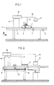
- FIG. 1 shows a schematic side view of the device according to the invention and FIG. 2 shows a view in the direction of arrow II in FIG. 1 shows a movable support 1 which carries burner 2.
- the burners 2 are water-cooled bundle burners, the flame direction of which is directed towards the head 3 of a rail 4.
- the burners are connected via gas lines 5 to a valve arrangement of a gas-oxygen mixing device which is shown schematically in FIG.
- limit switches 7 and 8 are arranged, which serve to limit the path of the support.
- Above the rail is a temperature measuring device 9, which is connected to a process computer 11 via signal lines 10.
- a display device for the measured temperature is designated by 12.
- the drive 13 for the support is arranged on the side next to the rail.
- the limit switches 7 and 8 for path limitation are also located in the area of the movable drive.
- the support can be moved on a table 14 and is supported on this table 14.
- the travel range of the support is usually limited to 600 to 900 mm, whereby the minimum travel path is usually chosen to be around 300 mm. Cooling in still air has proven to be sufficient to avoid undesired hardening and only to restore the state that prevailed before heating to the hot forming temperature.
Landscapes
- Chemical & Material Sciences (AREA)
- Engineering & Computer Science (AREA)
- Physics & Mathematics (AREA)
- Thermal Sciences (AREA)
- Crystallography & Structural Chemistry (AREA)
- Mechanical Engineering (AREA)
- Materials Engineering (AREA)
- Metallurgy (AREA)
- Organic Chemistry (AREA)
- Heat Treatment Of Articles (AREA)
- Manufacture And Refinement Of Metals (AREA)
- Furnace Charging Or Discharging (AREA)
- Screw Conveyors (AREA)
- Laying Of Electric Cables Or Lines Outside (AREA)
- Chutes (AREA)
- Seats For Vehicles (AREA)
- Heat Treatments In General, Especially Conveying And Cooling (AREA)
- Feeding, Discharge, Calcimining, Fusing, And Gas-Generation Devices (AREA)
- Underground Or Underwater Handling Of Building Materials (AREA)
- Excavating Of Shafts Or Tunnels (AREA)
- Manufacturing Of Electrical Connectors (AREA)
- Railway Tracks (AREA)
- Machines For Laying And Maintaining Railways (AREA)
- Paper (AREA)
- Electrical Discharge Machining, Electrochemical Machining, And Combined Machining (AREA)
Abstract
Description
Die Erfindung bezieht sich auf ein Verfahren zum Verhindern der Eindellung von Schienen im Übergangsbereich zwischen Zungenende und Zungenprofil sowie auf eine Vorrichtung zur Durchführung dieses Verfahrens.The invention relates to a method for preventing the indentation of rails in the transition area between the tongue end and tongue profile, and to an apparatus for performing this method.
Die Ausballung des Zungenschienenendes auf das Vignolschienenprofil erfolgt üblicherwiese durch Warmformgebung im Gesenk. Die hiefür erforderliche Erhitzung auf die Umformungstemperatur erfolgt in besonderen Glühöfen, wobei die Schienen jeweils auf eine entsprechende Länge in den Ofen eingesteckt werden. Der Ausballungsprozeß ist zumeist in drei Arbeitsstufen unterteilt, zwischen welchen jeweils ein Nachwärmen auf Umformungstemperatur erforderlich ist. Zum kalten Schienenende hin entsteht im Profil ein Temperaturübergangsbereich, der eine metallurgische Veränderung des Werkstoffgefüges zur Folge hat. Diese Gefügeveränderung, welche im besonderen in einem Temperaturbereich von 750 bis 760°C bei perlitischem Schienenstahl auftritt, hat eine Art Weichglüheffekt zur Folge. Je länger sich der Schienenstahl in diesem Temperaturbereich befindet, desto größer wird dieser Weichglüheffekt und damit der Festigkeitsabfall. Die Länge der Gefügeänderungszone ist direkt abhängig von der Umformungstemperatur und von der Zeitdauer des Warmumformungsprozesses. Der Festigkeitsabfall der Härtemulde erreicht Größenordnungen von 150 bis 200 N/mm2 und beim Radüberlauf ergibt sich in der Folge eine Dellenlänge, welche sich in einem Bereich von etwa 120 mm bewegt. Eine Dellenbildung kann nur dann verhindert werden, wenn der Längenbereich, in weichem ein Härteabfall bzw. eine Härtemulde beobachtet wird, auf etwa 30 mm beschränkt wird, da dann eine plastische Verformung auf Grund der Hertz'schen Flächenpreßung in Abhängigkeit vom Raddurchmesser und damit eine Dellenbildung zuverlässig verhindert wird. Bei einer Begrenzung der Gefügeänderungszone auf derartige Längen ist die Stützung des Randzonengefüges ausreichend, um eine plastische Verformung zu vermeiden.Bulging the tongue rail end onto the Vignol rail profile is usually done by hot forming in the die. The heating to the forming temperature required for this takes place in special annealing furnaces, the rails being inserted into the furnace to a corresponding length. The agglomeration process is usually divided into three work stages, between which reheating to the forming temperature is required. A temperature transition area is created in the profile towards the cold rail end, which results in a metallurgical change in the material structure. This structural change, which occurs in particular in a temperature range of 750 to 760 ° C with pearlitic rail steel, has a kind of soft annealing effect. The longer the rail steel is in this temperature range, the greater this soft annealing effect and thus the decrease in strength. The length of the structural change zone is directly dependent on the forming temperature and the duration of the hot forming process. The drop in strength of the hardness trough reaches orders of magnitude of 150 to 200 N / mm 2, and the wheel overflow results in a dent length which is in a range of approximately 120 mm. Dents can only be prevented if the length range in which a drop in hardness or a hardness trough is observed is limited to approximately 30 mm, since plastic deformation due to Hertzian surface pressure depending on the wheel diameter and thus a dent formation is reliably prevented. If the structure change zone is limited to such lengths, the support of the edge zone structure is sufficient to avoid plastic deformation.
Aus der DE-AS 25 41 978 ist bereits ein Verfahren zu entnehmen, bei welchem eine Wärmebehandlung von Schienen zum Zwecke der Ausbildung eines feinperlitischen Gefüges vorgenommen wird. Die Erwärmung erfaßt, ausgehend von einer kalten Schiene, die gesamte Länge derselben, wobei ein Durchlaufverfahren eingesetzt wird. Nach dem Erwärmen auf Temperaturen über der Austenitisierungstemperatur wird gesteuert unter Verwendung von Preßkluft bzw. Preßluft mit flüssigem Medium abgekühlt.DE-AS 25 41 978 already shows a process in which rails are heat-treated for the purpose of forming a fine pearlitic structure. Starting from a cold rail, the heating covers the entire length of the rail, using a continuous process. After heating to temperatures above the austenitizing temperature, cooling is carried out in a controlled manner using compressed air or compressed air with a liquid medium.
Die Erfindung zielt nun darauf ab, bei der Warmformgebung eine Absenkung der Festigkeit im Übergangsbereich zum kalten Schienenende zu vermeiden bzw. eine bereits erfolgte Gefügeänderung im Bereich der Umformung rückgängig zu machen. Zur Lösung dieser Aufgabe besteht das erfindungsgemäße Verfahren im wesentlichen darin, daß die Wärmebehandlung gleichzeitig mit der oder unmittelbar anschließend an die Warmumformung des Zungenschienenendes vorgenommen wird, daß der Übergangsbereich über eine Tiefe von wenigstens 7 mm, vorzugsweise wenigstens 10 mm, und vorzugsweise höchstens 25 mm, über die Austenitisierungstemperatur, insbesondere über 860°C, erwärmt wird und daß nach Erreichen der Austenitisierungstemperatur an ruhender Luft abgekühlt wird. Durch diese Wärmebehandlung wird der Urzustand des perlitischen Gefüges wieder hergestellt, wobei die gewählte Eindringtiefe im Hinblick darauf gewählt wurde, daß sich das Spannungsmaximum üblicherwiese etwa 7 mm unter der Werkstückoberfläche befindet. Ein wesentlicher Faktor für die Wärmebehandlung ist hiebei eine möglichst kurze Aufheizzeit auf Umformungstemperatur, um ein Ausbreiten der Wärme zum kalten Schienenende hin zu verhindern. Nach dem Ausballen der Zungenprofile auf Vignolprofile befinden sich die Werkstücke in einem Temperaturbereich von ca. 400 bis 450°C im Bereich der Gefügeänderungszone, wodurch die Aufheizzeit für die nachfolgende Wärmebehandlung wesentlich dadurch verkürzt werden kann, daß die Wärmebehandlung unmittelbar anschließend an die Warmformgebung des Zungenschienenendes vorgenommen wird. Auf diese Weise kann die Wärmebehandlung auf eine kurze Länge beschränkt werden. In vorteilhafter Weise wird die Wärmebehandlung auf den Schienenkopf beschränkt. Die Abkühlung erfolgt dann an ruhender Luft, wodurch der ursprüngliche Gefügezustand vor der Umformung erreicht wird.The aim of the invention is now to avoid lowering the strength in the transition area to the cold rail end during hot forming, or to undo an existing structural change in the area of the forming. To achieve this object, the method according to the invention essentially consists in that the heat treatment is carried out simultaneously with or immediately after the hot forming of the tongue rail end, that the transition region has a depth of at least 7 mm, preferably at least 10 mm, and preferably at most 25 mm , is heated above the austenitizing temperature, in particular above 860 ° C., and is cooled in still air after reaching the austenitizing temperature. This heat treatment restores the original state of the pearlitic structure, the selected depth of penetration being chosen with a view to the fact that the maximum stress is usually about 7 mm below the workpiece surface. An essential factor for heat treatment is the shortest possible heating time to the forming temperature in order to prevent the heat from spreading to the cold rail end. After baling the tongue profiles onto Vignol profiles, the workpieces are in a temperature range of approx. 400 to 450 ° C in the area of the microstructure change zone, whereby the heating-up time for the subsequent heat treatment can be shortened considerably by the fact that the heat treatment immediately after the hot shaping of the tongue rail end is made. In this way, the heat treatment can be limited to a short length. The heat treatment is advantageously limited to the rail head. The cooling then takes place in still air, whereby the original structural state is reached before the forming.
In bevorzugter Weise'wird erfindungsgemäß so vorgegangen, daß an der Übergangszone zwischen Regelschienenprofil und Zungenende ein Längenbereich von wenigstens 150 mm, vorzugsweise wenigstens 300 mm, der Wärmebehandlung unterworfen wird. Der maximale Längenbereich kann je nach Dauer des Warmumformungsprozesses in der Regel auf unter 900 mm begrenzt werden. Die Steuerung der Wärmebehandlung wird vorzugsweise so vorgenommen, daß die Länge der durch Umformen der Zunge entstandenen Gefügeänderungszone in Schienenlängsrichtung kleiner 30 mm gehalten wird.In a preferred manner, the procedure according to the invention is such that a length range of at least 150 mm, preferably at least 300 mm, is subjected to the heat treatment at the transition zone between the standard rail profile and the tongue end. The maximum length range can vary depending on the duration of the hot forming process This is usually limited to less than 900 mm. The control of the heat treatment is preferably carried out in such a way that the length of the structural change zone formed by reshaping the tongue is kept less than 30 mm in the longitudinal direction of the rail.
Die erfindungsgemäße Vorrichtung zur Durchführung dieses Verfahrens ist im wesentlichen dadurch gekennzeichnet, daß ein Brenner mit steuerbarer Flammtemperatur über die Oberfläche der Schiene verfahrbar gelagert ist, dessen Verfahrweg, vorzugsweise durch verstellbare Endschalter, begrenzt ist, daß der Brenner in einem Support mit reversierbarem Antrieb gelagert ist und daß ein Temperaturmeßgerät zur Erfassung der Oberflächentemperatur der Schiene vorgesehen ist. In besonders vorteilhafter Weise ist hiebei die Ausbildung so getroffen, daß die Brenngas-und/oder Verbrennungsluft-bzw. Sauerstoffzufuhr und/oder die lineare Fahrgeschwindigkeit des Brenners längs der Schiene in Abhängigkeit von Temperaturmeßwerten geregelt ist, wobei vorzugsweise das Temperaturmeßgerät über Steuerleitungen mit einem Prozeßrechner verbunden ist, welcher mit einer steuerbaren Ventilanordnung einer Gas-Sauerstoffmischeinrichtung für den Brenner verbunden ist. Um dem nichtlinearen Temperaturverlauf im Temperaturübergangsbereich Rechnung zu tragen, erweist sich eine prozeßrechnergesteuerte Anlage als besonders vorteilhaft. Die Brennerbündel sind hiebei auf einem Support montiert und die Wärmebehandlungslänge kann über Endschalter optimal eingestellt werden. Das Wärmeeinbringen kann über ein, beispielsweise als Miliskop bzw. Pyrometer, ausgebildetes Temperaturmeßgerät überwacht werden, wobei die Härte der Flamme durch einen Prozeßrechner geregelt werden kann und insbesondere im Aufheizvorgang mit harter Flamme gefahren wird und im Haltestadium nur mit weicher Flamme gefahren wird. Auf diese Weise kann ein Überhitzen der Bereiche, die sich bereits auf Umwandlungstemperatur befinden, ausgeschlossen werden.The device according to the invention for carrying out this method is essentially characterized in that a burner with a controllable flame temperature is mounted such that it can be moved over the surface of the rail, the travel of which is limited, preferably by adjustable limit switches, that the burner is mounted in a support with a reversible drive and that a temperature measuring device is provided for detecting the surface temperature of the rail. In a particularly advantageous manner, the design is such that the fuel gas and / or combustion air or. Oxygen supply and / or the linear travel speed of the burner along the rail is regulated as a function of temperature measurement values, the temperature measurement device preferably being connected via control lines to a process computer which is connected to a controllable valve arrangement of a gas-oxygen mixing device for the burner. In order to take account of the non-linear temperature profile in the temperature transition area, a process computer-controlled system has proven to be particularly advantageous. The burner bundles are mounted on a support and the heat treatment length can be optimally adjusted using limit switches. The introduction of heat can be monitored via a temperature measuring device, for example as a miliscope or pyrometer, whereby the hardness of the flame can be regulated by a process computer and in particular is operated with a hard flame in the heating process and is only operated with a soft flame in the holding stage. In this way, overheating of the areas that are already at the transition temperature can be ruled out.
Die Erfindung wird nachfolgend anhand eines in der Zeichnung schematisch dargestellten Ausführungsbeispieles einer Vorrichtung zur Durchführung des erfindungsgemäßen Verfahrens näher erläutert. In dieser zeigen Fig.1 eine - schematische Seitenansicht der erfindungsgemäßen Vorrichtung und Fig.2 eine Ansicht in Richtung des Pfeiles II der Fig.1. In Fig.1 ist ein verfahrbarer Support 1 ersichtlich, welcher Brenner 2 trägt. Bei den Brennern 2 handelt es sich um wassergekühlte Bündelbrenner, deren Flammrichtung auf den Kopf 3 einer Schiene 4 gerichtet ist. Die Brenner stehen über Gasleitungen 5 mit einer in Fig.2 ersichtlichen schematisch mit 6 angedeuteten Ventilanordnung einer Gas-Sauerstoffmischeinrichtung in Verbindung. Im Verschiebeweg des Supports 1 sind Endschalter 7 und 8 angeordnet, welche als Wegbegrenzung für den Verfahrweg des Supportes dienen. Oberhalb der Schiene befindet sich ein Temperaturmeßgerät 9, welches über Signalleitungen 10 mit einem Prozeßrechner 11 verbunden ist. Ein Anzeigegerät für die gemessene Temperatur ist mit 12 bezeichnet.The invention is explained in more detail below with reference to an exemplary embodiment of a device for carrying out the method according to the invention, which is shown schematically in the drawing. 1 shows a schematic side view of the device according to the invention and FIG. 2 shows a view in the direction of arrow II in FIG. 1 shows a movable support 1 which carries
Wie aus Fig.2 ersichtlich, ist der Antrieb 13 für den Support seitlich neben der Schiene angeordnet. Im Bereich des verfahrbaren Antriebes befinden sich auch die Endschalter 7 und 8 für die Wegbegrenzung. Der Support ist auf einem Tisch 14 verfahrbar und an diesem Tisch 14 abgestützt. Der Verfahrbereich des Supportes wird üblicherwiese mit 600 bis 900 mm begrenzt, wobei der minimale Verfahrweg üblicherweise mit etwa 300 mm gewählt wird. Die Abkühlung an ruhender Luft hat sich als ausreichend erwiesen, um eine unerwünschte Aufhärtung zu vermeiden und lediglich den Zustand wiederum herzustellen, welcher vor der Aufheizung auf Warmumformungstemperatur vorherrschte.As can be seen from FIG. 2, the
Claims (7)
Applications Claiming Priority (2)
| Application Number | Priority Date | Filing Date | Title |
|---|---|---|---|
| AT0088785A AT391707B (en) | 1985-03-25 | 1985-03-25 | METHOD FOR PREVENTING ADJUSTMENT OF RAILS IN THE TRANSITIONAL AREA AND DEVICE FOR CARRYING OUT THIS METHOD |
| AT887/85 | 1985-03-25 |
Publications (3)
| Publication Number | Publication Date |
|---|---|
| EP0199706A2 true EP0199706A2 (en) | 1986-10-29 |
| EP0199706A3 EP0199706A3 (en) | 1987-05-13 |
| EP0199706B1 EP0199706B1 (en) | 1990-03-14 |
Family
ID=3502117
Family Applications (1)
| Application Number | Title | Priority Date | Filing Date |
|---|---|---|---|
| EP86890076A Expired - Lifetime EP0199706B1 (en) | 1985-03-25 | 1986-03-24 | Method and device for preventing the denting of rails in the transition area between the end and the full section of the tongue |
Country Status (9)
| Country | Link |
|---|---|
| EP (1) | EP0199706B1 (en) |
| AT (2) | AT391707B (en) |
| CS (1) | CS266577B2 (en) |
| DD (1) | DD244990A5 (en) |
| DE (1) | DE3669538D1 (en) |
| HU (1) | HU195545B (en) |
| NO (1) | NO161632C (en) |
| PL (1) | PL145456B1 (en) |
| YU (2) | YU44545B (en) |
Family Cites Families (6)
| Publication number | Priority date | Publication date | Assignee | Title |
|---|---|---|---|---|
| GB448416A (en) * | 1933-09-06 | 1936-05-27 | Oxweld Railroad Service Compan | Improvements in or relating to the surface hardening of rails and to rails treated thereby |
| US2484897A (en) * | 1946-10-22 | 1949-10-18 | Linde Air Prod Co | Apparatus for heat-treating surfaces of rails |
| DE800867C (en) * | 1949-10-25 | 1950-12-11 | Deutsche Bundesbahn | Method and device for removing corrugations on rails |
| BE626486A (en) * | 1961-12-27 | |||
| DE2541978C3 (en) * | 1975-09-20 | 1978-08-24 | Butzbacher Weichenbau Gmbh, 6308 Butzbach | Process for the heat treatment of switch parts in a continuous process |
| DE2821227C2 (en) * | 1978-05-16 | 1982-12-23 | Krupp Stahl Ag, 4630 Bochum | Process for the production of rails with reduced corrugation |
-
1985
- 1985-03-25 AT AT0088785A patent/AT391707B/en not_active IP Right Cessation
-
1986
- 1986-03-12 YU YU365/86A patent/YU44545B/en unknown
- 1986-03-19 HU HU861158A patent/HU195545B/en not_active IP Right Cessation
- 1986-03-19 CS CS861937A patent/CS266577B2/en unknown
- 1986-03-21 NO NO861149A patent/NO161632C/en unknown
- 1986-03-24 AT AT86890076T patent/ATE51036T1/en not_active IP Right Cessation
- 1986-03-24 DD DD86288247A patent/DD244990A5/en not_active IP Right Cessation
- 1986-03-24 PL PL1986258590A patent/PL145456B1/en unknown
- 1986-03-24 DE DE8686890076T patent/DE3669538D1/en not_active Expired - Lifetime
- 1986-03-24 EP EP86890076A patent/EP0199706B1/en not_active Expired - Lifetime
-
1987
- 1987-09-04 YU YU1643/87A patent/YU44642B/en unknown
Also Published As
| Publication number | Publication date |
|---|---|
| DD244990A5 (en) | 1987-04-22 |
| DE3669538D1 (en) | 1990-04-19 |
| YU44545B (en) | 1990-08-31 |
| YU44642B (en) | 1990-10-31 |
| AT391707B (en) | 1990-11-26 |
| PL145456B1 (en) | 1988-09-30 |
| YU36586A (en) | 1988-06-30 |
| EP0199706B1 (en) | 1990-03-14 |
| NO161632B (en) | 1989-05-29 |
| YU164387A (en) | 1988-12-31 |
| ATE51036T1 (en) | 1990-03-15 |
| EP0199706A3 (en) | 1987-05-13 |
| ATA88785A (en) | 1990-05-15 |
| HUT43655A (en) | 1987-11-30 |
| NO161632C (en) | 1989-09-06 |
| CS193786A2 (en) | 1989-04-14 |
| HU195545B (en) | 1988-05-30 |
| CS266577B2 (en) | 1990-01-12 |
| NO861149L (en) | 1986-09-26 |
Similar Documents
| Publication | Publication Date | Title |
|---|---|---|
| EP2012948B1 (en) | Method for reshaping metal blanks made of superior and supreme hardness steels | |
| EP0186373B1 (en) | Method of and apparatus for heat treating rails | |
| EP1412543B1 (en) | Method for cooling work pieces especially shape-rolled products from rail steel | |
| EP3303642B1 (en) | Method for contactlessly cooling steel sheets and device therefor | |
| EP2097544B1 (en) | Method and apparatus for the heat treatment of welds | |
| EP2106305A1 (en) | Device for flame straightening | |
| DE19619171C1 (en) | Method of heat treatment of welded connections of rail tracks | |
| CH668728A5 (en) | Method and device for connecting werkstueckteilen. | |
| AT391707B (en) | METHOD FOR PREVENTING ADJUSTMENT OF RAILS IN THE TRANSITIONAL AREA AND DEVICE FOR CARRYING OUT THIS METHOD | |
| EP0632137B1 (en) | Process for the thermal pretreatment of metallic articles | |
| DE3744044A1 (en) | METHOD FOR THE HEAT TREATMENT OF THE WELDING SEAM ON LONG-WELDED METAL TUBES AND DEVICE FOR CARRYING OUT THE METHOD | |
| DE3638816C1 (en) | Method for the production of steel rails with low residual stress by means of roller straightening | |
| CH621364A5 (en) | Process and equipment for the heat treatment of switch components | |
| DE1496004B1 (en) | Method of tempering a sheet of glass | |
| EP0190448A1 (en) | Process for reducing residual stress of roller-straightened steel rails | |
| EP0416356A2 (en) | Device for producing steel strip | |
| DE3016259C2 (en) | Process for multi-layer arc welding of ferritic, tempered steels and for the subsequent heat treatment of the welding point and device for carrying out the process | |
| AT18135U1 (en) | Method and a device for welding passable components of a track using flash butt welding | |
| DE655383C (en) | Device for the heat treatment of welding, flame cutting and the like. The like. Zones of workpieces that have changed in their structure or are partially subject to tension | |
| DE662453C (en) | Annealing process to prepare hard-braked steel rail wheels for turning off the flattened wheel tread | |
| AT248202B (en) | Method and device for the heat treatment of rail connection and surfacing welds | |
| DE1496004C (en) | Method of tempering a sheet of glass | |
| DE2940826A1 (en) | Deep hardening of workpieces, esp. railway rails - where brief surface quenching and controlled cooling produces fine sorbite structure with high wear resistance | |
| DE2344234C3 (en) | Pusher furnace for heating metal workpieces | |
| DE1004896B (en) | Method and device for soldering together bodies with different coefficients of thermal expansion |
Legal Events
| Date | Code | Title | Description |
|---|---|---|---|
| PUAI | Public reference made under article 153(3) epc to a published international application that has entered the european phase |
Free format text: ORIGINAL CODE: 0009012 |
|
| AK | Designated contracting states |
Kind code of ref document: A2 Designated state(s): AT BE CH DE FR GB IT LI LU NL SE |
|
| PUAL | Search report despatched |
Free format text: ORIGINAL CODE: 0009013 |
|
| AK | Designated contracting states |
Kind code of ref document: A3 Designated state(s): AT BE CH DE FR GB IT LI LU NL SE |
|
| 17P | Request for examination filed |
Effective date: 19870813 |
|
| 17Q | First examination report despatched |
Effective date: 19880915 |
|
| GRAA | (expected) grant |
Free format text: ORIGINAL CODE: 0009210 |
|
| AK | Designated contracting states |
Kind code of ref document: B1 Designated state(s): AT BE CH DE FR GB IT LI LU NL SE |
|
| REF | Corresponds to: |
Ref document number: 51036 Country of ref document: AT Date of ref document: 19900315 Kind code of ref document: T |
|
| ITF | It: translation for a ep patent filed | ||
| REF | Corresponds to: |
Ref document number: 3669538 Country of ref document: DE Date of ref document: 19900419 |
|
| GBT | Gb: translation of ep patent filed (gb section 77(6)(a)/1977) | ||
| ET | Fr: translation filed | ||
| PLBE | No opposition filed within time limit |
Free format text: ORIGINAL CODE: 0009261 |
|
| STAA | Information on the status of an ep patent application or granted ep patent |
Free format text: STATUS: NO OPPOSITION FILED WITHIN TIME LIMIT |
|
| 26N | No opposition filed | ||
| ITPR | It: changes in ownership of a european patent |
Owner name: CESSIONE;VOEST - ALPINE EISENBAHNSYSTEME GESELLSCH |
|
| REG | Reference to a national code |
Ref country code: GB Ref legal event code: 732 |
|
| REG | Reference to a national code |
Ref country code: CH Ref legal event code: PUE Owner name: VOEST-ALPINE EISENBAHNSYSTEME GESELLSCHAFT M.B.H. |
|
| REG | Reference to a national code |
Ref country code: FR Ref legal event code: TP |
|
| NLS | Nl: assignments of ep-patents |
Owner name: VOEST-ALPINE EISENBAHNSYSTEME GESELLSCHAFT M.B.H. |
|
| BECA | Be: change of holder's address |
Free format text: 920331 *VOEST-ALPINE EISENBAHNSYSTEME G.M.B.H.:FLORAGASSE 7, 1040 WIEN |
|
| ITTA | It: last paid annual fee | ||
| EPTA | Lu: last paid annual fee | ||
| EAL | Se: european patent in force in sweden |
Ref document number: 86890076.2 |
|
| PGFP | Annual fee paid to national office [announced via postgrant information from national office to epo] |
Ref country code: SE Payment date: 19960219 Year of fee payment: 11 |
|
| PGFP | Annual fee paid to national office [announced via postgrant information from national office to epo] |
Ref country code: NL Payment date: 19960222 Year of fee payment: 11 |
|
| PGFP | Annual fee paid to national office [announced via postgrant information from national office to epo] |
Ref country code: DE Payment date: 19960223 Year of fee payment: 11 |
|
| PG25 | Lapsed in a contracting state [announced via postgrant information from national office to epo] |
Ref country code: SE Effective date: 19970325 |
|
| PG25 | Lapsed in a contracting state [announced via postgrant information from national office to epo] |
Ref country code: NL Effective date: 19971001 |
|
| NLV4 | Nl: lapsed or anulled due to non-payment of the annual fee |
Effective date: 19971001 |
|
| PG25 | Lapsed in a contracting state [announced via postgrant information from national office to epo] |
Ref country code: DE Effective date: 19971202 |
|
| EUG | Se: european patent has lapsed |
Ref document number: 86890076.2 |
|
| PGFP | Annual fee paid to national office [announced via postgrant information from national office to epo] |
Ref country code: GB Payment date: 19980213 Year of fee payment: 13 Ref country code: FR Payment date: 19980213 Year of fee payment: 13 |
|
| PGFP | Annual fee paid to national office [announced via postgrant information from national office to epo] |
Ref country code: AT Payment date: 19980223 Year of fee payment: 13 |
|
| PGFP | Annual fee paid to national office [announced via postgrant information from national office to epo] |
Ref country code: CH Payment date: 19980224 Year of fee payment: 13 |
|
| PGFP | Annual fee paid to national office [announced via postgrant information from national office to epo] |
Ref country code: LU Payment date: 19980303 Year of fee payment: 13 |
|
| PGFP | Annual fee paid to national office [announced via postgrant information from national office to epo] |
Ref country code: BE Payment date: 19980320 Year of fee payment: 13 |
|
| PG25 | Lapsed in a contracting state [announced via postgrant information from national office to epo] |
Ref country code: LU Free format text: LAPSE BECAUSE OF NON-PAYMENT OF DUE FEES Effective date: 19990324 Ref country code: GB Free format text: LAPSE BECAUSE OF NON-PAYMENT OF DUE FEES Effective date: 19990324 Ref country code: AT Free format text: LAPSE BECAUSE OF NON-PAYMENT OF DUE FEES Effective date: 19990324 |
|
| PG25 | Lapsed in a contracting state [announced via postgrant information from national office to epo] |
Ref country code: LI Free format text: LAPSE BECAUSE OF NON-PAYMENT OF DUE FEES Effective date: 19990331 Ref country code: CH Free format text: LAPSE BECAUSE OF NON-PAYMENT OF DUE FEES Effective date: 19990331 Ref country code: BE Free format text: LAPSE BECAUSE OF NON-PAYMENT OF DUE FEES Effective date: 19990331 |
|
| BERE | Be: lapsed |
Owner name: VOEST-ALPINE EISENBAHNSYSTEME G.M.B.H. Effective date: 19990331 |
|
| REG | Reference to a national code |
Ref country code: CH Ref legal event code: PL |
|
| GBPC | Gb: european patent ceased through non-payment of renewal fee |
Effective date: 19990324 |
|
| PG25 | Lapsed in a contracting state [announced via postgrant information from national office to epo] |
Ref country code: FR Free format text: LAPSE BECAUSE OF NON-PAYMENT OF DUE FEES Effective date: 19991130 |
|
| REG | Reference to a national code |
Ref country code: FR Ref legal event code: ST |
|
| PG25 | Lapsed in a contracting state [announced via postgrant information from national office to epo] |
Ref country code: IT Free format text: LAPSE BECAUSE OF NON-PAYMENT OF DUE FEES;WARNING: LAPSES OF ITALIAN PATENTS WITH EFFECTIVE DATE BEFORE 2007 MAY HAVE OCCURRED AT ANY TIME BEFORE 2007. THE CORRECT EFFECTIVE DATE MAY BE DIFFERENT FROM THE ONE RECORDED. Effective date: 20050324 |