EP0199612A1 - Mehrpoliges Schaltgerät mit Fernsteuerung - Google Patents
Mehrpoliges Schaltgerät mit Fernsteuerung Download PDFInfo
- Publication number
- EP0199612A1 EP0199612A1 EP86400544A EP86400544A EP0199612A1 EP 0199612 A1 EP0199612 A1 EP 0199612A1 EP 86400544 A EP86400544 A EP 86400544A EP 86400544 A EP86400544 A EP 86400544A EP 0199612 A1 EP0199612 A1 EP 0199612A1
- Authority
- EP
- European Patent Office
- Prior art keywords
- input
- circuit
- input terminal
- command
- state
- Prior art date
- Legal status (The legal status is an assumption and is not a legal conclusion. Google has not performed a legal analysis and makes no representation as to the accuracy of the status listed.)
- Granted
Links
Images


Classifications
-
- H—ELECTRICITY
- H01—ELECTRIC ELEMENTS
- H01H—ELECTRIC SWITCHES; RELAYS; SELECTORS; EMERGENCY PROTECTIVE DEVICES
- H01H47/00—Circuit arrangements not adapted to a particular application of the relay and designed to obtain desired operating characteristics or to provide energising current
- H01H47/02—Circuit arrangements not adapted to a particular application of the relay and designed to obtain desired operating characteristics or to provide energising current for modifying the operation of the relay
-
- H—ELECTRICITY
- H01—ELECTRIC ELEMENTS
- H01H—ELECTRIC SWITCHES; RELAYS; SELECTORS; EMERGENCY PROTECTIVE DEVICES
- H01H89/00—Combinations of two or more different basic types of electric switches, relays, selectors and emergency protective devices, not covered by any single one of the other main groups of this subclass
- H01H89/06—Combination of a manual reset circuit with a contactor, i.e. the same circuit controlled by both a protective and a remote control device
- H01H89/08—Combination of a manual reset circuit with a contactor, i.e. the same circuit controlled by both a protective and a remote control device with both devices using the same contact pair
Definitions
- the object of the invention is to increase the possibilities of using such a device by adapting the remote control unit to various control signals allowing multiple operation.
- the first command corresponds to a remote control operating mode.
- the selector allows the state of the position detector of the movable main contact to be taken into account
- the second command is assimilated to an operating mode in contactor.
- the selector neutralizes the position detector signal
- the second input terminal corresponds to an impulse input decoupled from the first command, so as to authorize a command of the pilot switch type.
- control can be carried out via the auxiliary contact block of the device without using additional components, in particular diode devices or decoupling relays.
- the first input terminal TL and the second input terminal CT are distinct from each other, and are accessible simultaneously, allowing coexistence between the first pulse command and the second mixed command depending on the state of the selector. adjustment.
- a priority code exists between these two commands, as well as a function to refresh the states of the electronic circuit in the event of a power supply interruption.
- French patent application No. 2,536,904 has already proposed an electronic circuit for controlling a multifunction apparatus fitted with an electromagnet mechanism.
- the position sensor of the device's contacts always remains on, and the adjustment selector has several selection pads arranged between the output of the combinational logic circuit and the input of the monostable rocker.
- the selection of a predetermined pad authorizes a precise operation of the apparatus, for example in remote control mode, or in contactor mode, but not both at the same time.
- the association of such an electronic circuit with a device of the aforementioned type would limit its possibilities of applications, and would also have the disadvantage of generating an electrical counter-order in the event of forced operation by manual opening or closing operation. closing by the second organ.
- Another object of the invention consists in authorizing forced operation by the second manual member for opening or closing the contacts, without issuing a counter-command by the electronic circuit.
- the apparatus according to the invention is characterized in that the electronic circuit for controlling the electromagnet comprises a sequential logic circuit sensitive to the state of the control signal applied to the second input terminal CT, and to the state of the detector in the active position of the selector, and that timing or shaping means modify the internal state of the logic circuit by making the detector signal passive following forced opening or closing operation by the second manual organ.
- the timing means of the sequential logic circuit are formed by a diverter device intended to derive the control signal applied to the second input terminal CT.
- the static switch in particular a field effect power transistor, is connected in series with the electromagnet, and is controlled by a monostable flip-flop controlled by the control pulse applied to the first input terminal TL, and by the state of the sequential logic circuit.
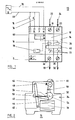
- a remote-controlled current cut-off device represented by the general reference 10 comprises two unipolar cut-off blocks 12, 14 or poles, attached to a remote control block 16 to constitute a modular bipolar control system remotely.
- Each pole 12, 14 is housed in an individual casing of molded insulating material, and contains a cut-off mechanism of the type described in detail in French patent application No. 2,535,520 of the applicant.
- the two poles 12, 14 constitute the power circuit and are provided with two incoming terminals 18, 20 connected to the low voltage distribution network by two supply lines 22, 24, and two starting terminals 26, 28 connected to a load (not shown) by two connecting conductors 30, 32.
- the poles 12, 14 can of course be assembled in a single bipolar box. Three or four identical poles can also be juxtaposed to form a three-pole or four-pole breaking device.
- Each pole 12, 14 has a movable main contact 33 bistable actuated between the two closed and open positions of the device.
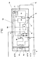
- the remote control unit 16 is equipped with a remote control mechanism 34 (fig. 2) intended to ensure the tilting of the movable contact 33 from the closed position to the open position, and vice versa, following an applied remote control command. to an electromagnetic actuator with electromagnet 36.
- a magneto-thermal trip device associated with a mechanism automatic trigger 38 cooperating with the movable contact 33 to move it to the open position in the event of overload and / or fault, and maintain it in this position regardless of the position of the remote control mechanism 16 as long as the trigger mechanism 38 is in the triggered position.
- a return to service requires actuation of a manual reset lever 40 of the trigger mechanism 38 to authorize in the armed position of the latter a remote-controlled closure of the device by the remote control unit 16.
- the electromagnet 36 of the remote control unit 16 is provided with a plunger core 42 acting on a pivoting lever 44 articulated at its opposite end on a fixed point 46 of the insulating case 48.
- the lever 44 carries a pusher 50 cooperating mechanically with a rocker 52 mounted with limited rotation on a fixed axis 54, and with a return spring 56 in the form of a blade.
- the rocker 52 is coupled by a connecting rod 58 to a pivoting lever 60 constituting an emergency control member intended to manually open or close the device 10.
- the lever 60 for manual control is also connected to an arm 62 which can 'straddle in a balance (not shown) acting on the movable contacts 33 of the poles 12, 14, so as to mechanically secure the balance and the rocker 52.
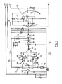
- the remote control unit 16 comprises four connection terminals CT, TL, P and N in internal connection with an electronic circuit 66 for controlling the electromagnet 36 (FIGS. 1 and 3).
- the two terminals P and N are supply terminals connected by conductors 68, 70 external to an AC or DC voltage source 72. for example 220 Volts.
- the input terminal TL is assigned to a first impulse command of the remote control type, the impulse signal being generated by the actuation of a first switch or monostable contact, in particular a push button 74, interconnected between the terminal TL and the conductor 68.
- the input terminal CT is used for a second mixed command, which depends on the state of an adjustment selector S, the function of which will be described in detail below.
- the monostable flip-flop 82 can be constituted by an integrated circuit 4093 with two inverters 86 , 88 associated with an RC timing circuit.
- the flip-flop 82 and the logic circuit 84 are supplied by a direct voltage Vcc delivered by a power supply unit 90 comprising a Zener diode 92 disposed in parallel on a filter cell with capacitor 94 and resistor 96, the assembly being connected to the terminals output of rectifier bridge 77.
- the detector 98 may be formed by a REED relay, the control contact 99 of which is actuated by a permanent magnet secured to a transmission member 100 (in dotted lines in FIG. 3) of the movement of the main movable contacts 33, as described in French Patent No. 2,536,904.
- the contact 99 of the detector 98 is either open or closed when the main contacts 33 are respectively in the open or closed position.
- the logic circuit 84 includes an input inverter 102 connected to the terminal CT by a resistor 104.
- the output of the inverter 102 is connected simultaneously to an inverter 106 which controls one of the inputs E1 of a first NAND logic gate 108, and to one of the inputs E3 of a second NAND logic gate 110.
- the selector S comprises a contact pad in series with the contact 99 for controlling the detector 98 between ground and a midpoint 112, the latter being connected to the positive pole of the supply voltage Vcc by a resistor 114.
- the midpoint 112 is connected on the one hand to the other input E2 of the first NAND gate 108 and on the other hand to an inverter 115 connected to the another entrance E4 from the second NAND 110 door.
- Two branch circuits 116, 118 derive the control slot applied to the input terminal CT to obtain a control pulse on the inputs E1, E3 of the NAND gates 108 and 110.
- the first branch circuit 116 comprises a capacitor C1 connected between the output of the inverter 106 and the input E1 of the gate 108, and a diode D1 and resistance R1 assembly connected in parallel between the input E1 and the ground.
- the second branch circuit 118 includes a capacitor C2 connected between the output of the inverter 102 and the input E3 of the gate 110, and a resistor R2 and diode D2 assembly connected in parallel between the input E3 and the ground.
- the anode of each diode D1 and D2 is at ground potential.
- the action of the detector 98 is neutralized by interrupting the circuit between the detector 98 and the midpoint 112.
- the input terminal CT can constitute a second impulse command input, decoupled from the input terminal TL associated with the first impulse command. This results in a possibility of carrying out, via the auxiliary contact block CAOF (not shown in FIG. 1) of the device 10, commands of the pilot remote control type, requiring no additional component, such as diode systems or decoupling relay.
- the two input terminals TL and CT are simultaneously accessible allowing coexistence between the first command by pulses, and the second assignable command according to the state of the selector S.
- a priority code is provided between these two types of command: priority belongs to the order that received the most recent order.
- the control commands applied to the terminals TL and CT correspond to edges, which means that the last validated edge imposes its state on the electromagnet 36.
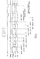
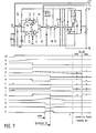
- FIGS. 7 and 8 show, in the active position of the selector S, a detailed phase of a timing diagram in contactor mode showing the signals A to P at different points of the electronic circuit 66 of FIG. 4, respectively during a remote control for closing and opening the main contacts 33.
- No pulse is applied during this phase to the input terminal TL
- the differentiator circuit 116 which derives the order command CT, so as to apply a pulse E to the input E1 of the NAND gate 108 instead of the permanent logic 1 state of the signal D during a closing remote control (FIG. 7).
- the second branch circuit 118 which applies a pulse F to the input E3 of the NAND gate 110 instead of the permanent logic 1 state of the signal B during an opening remote control (FIG.
- FIG. 8 is simulated beyond the instant t2, manual closing by the lever 60 intervening after a remote control for opening the contacts 33.
- the input terminals CT and TL of the electronic control circuit 66 are practically insensitive to the capacitive currents likely to appear on a very long connection cable connecting the contacts 76, 74 to the corresponding terminals CT, TL.
- the voltage VN between the supply terminal N and the earth of the electronic circuit 66 is constituted by a periodic signal with positive half-waves, determined by a diode 78 of the rectifier bridge 77.
- the leakage capacity of the connecting cable is positively charged at a value substantially equal to the average voltage of VN.
- the voltage at the input of the inverter 102 of the logic circuit 84, and of the inverter 86 of the monostable flip-flop 82 is close to zero.
- the CT and TL terminals undergo very significant attenuation at the currents generated by the parasitic capacitance of the cable (attenuation greater than a factor of 10).
Landscapes
- Selective Calling Equipment (AREA)
- Crushing And Pulverization Processes (AREA)
- Percussion Or Vibration Massage (AREA)
- Remote Monitoring And Control Of Power-Distribution Networks (AREA)
- Keying Circuit Devices (AREA)
- Driving Mechanisms And Operating Circuits Of Arc-Extinguishing High-Tension Switches (AREA)
- Breakers (AREA)
- Burglar Alarm Systems (AREA)
- Devices That Are Associated With Refrigeration Equipment (AREA)
- Absorbent Articles And Supports Therefor (AREA)
- Harvester Elements (AREA)
- Fire Alarms (AREA)
- Relay Circuits (AREA)
Priority Applications (1)
| Application Number | Priority Date | Filing Date | Title |
|---|---|---|---|
| AT86400544T ATE44632T1 (de) | 1985-03-26 | 1986-03-14 | Mehrpoliges schaltgeraet mit fernsteuerung. |
Applications Claiming Priority (2)
| Application Number | Priority Date | Filing Date | Title |
|---|---|---|---|
| FR8504620 | 1985-03-26 | ||
| FR8504620A FR2579821B1 (fr) | 1985-03-26 | 1985-03-26 | Appareil de coupure multipolaire a telecommande |
Publications (2)
| Publication Number | Publication Date |
|---|---|
| EP0199612A1 true EP0199612A1 (de) | 1986-10-29 |
| EP0199612B1 EP0199612B1 (de) | 1989-07-12 |
Family
ID=9317671
Family Applications (1)
| Application Number | Title | Priority Date | Filing Date |
|---|---|---|---|
| EP86400544A Expired EP0199612B1 (de) | 1985-03-26 | 1986-03-14 | Mehrpoliges Schaltgerät mit Fernsteuerung |
Country Status (11)
| Country | Link |
|---|---|
| US (1) | US4714976A (de) |
| EP (1) | EP0199612B1 (de) |
| JP (1) | JPH0831294B2 (de) |
| AT (1) | ATE44632T1 (de) |
| AU (1) | AU588167B2 (de) |
| CA (1) | CA1247729A (de) |
| DE (1) | DE3664395D1 (de) |
| ES (1) | ES8702735A1 (de) |
| FR (1) | FR2579821B1 (de) |
| PT (1) | PT82260B (de) |
| ZA (1) | ZA862184B (de) |
Cited By (8)
| Publication number | Priority date | Publication date | Assignee | Title |
|---|---|---|---|---|
| EP0292852A2 (de) * | 1987-05-26 | 1988-11-30 | Matsushita Electric Works, Ltd. | Fernbedienbarer Schalter |
| FR2628260A1 (fr) * | 1988-03-04 | 1989-09-08 | Telemecanique Electrique | Appareil de protection a contacts commandables par un electroaimant |
| EP0362085A1 (de) * | 1988-09-30 | 1990-04-04 | Merlin Gerin | Schaltgerät mit Fernsteuerung |
| EP0424283A1 (de) * | 1989-10-20 | 1991-04-24 | Merlin Gerin | Steuervorrichtung für einen ferngesteuerten Schalter |
| FR2799572A1 (fr) * | 1999-10-11 | 2001-04-13 | Schneider Electric Ind Sa | Contacteur-disjoncteur |
| FR2799574A1 (fr) * | 1999-10-11 | 2001-04-13 | Schneider Electric Ind Sa | Contacteur-disjoncteur |
| CN103560050A (zh) * | 2013-10-30 | 2014-02-05 | 武汉烽火富华电气有限责任公司 | 一种继电保护开关量输出回路启动电路及方法 |
| FR3114680A1 (fr) * | 2020-09-30 | 2022-04-01 | Schneider Electric Industries Sas | Dispositif de communication pour un appareil de commutation électrique |
Families Citing this family (8)
| Publication number | Priority date | Publication date | Assignee | Title |
|---|---|---|---|---|
| JP2600690B2 (ja) * | 1987-07-07 | 1997-04-16 | 日本電気株式会社 | 電源回路 |
| DE69315040T2 (de) * | 1992-06-19 | 1998-03-05 | Square D Co | Überlagerter handbetätigungsmechanismus für ferngesteuerten schutzschalter |
| US5289148A (en) * | 1992-12-02 | 1994-02-22 | Intelligent Electrical Products, Inc. | Adaptable power switch module for circuit breaker panels |
| US6862869B2 (en) * | 1999-10-14 | 2005-03-08 | Stewart Systems, Inc. | Pattern former for wrapped bakery products |
| US7692112B2 (en) * | 2006-01-10 | 2010-04-06 | Siemens Industry, Inc. | Control module |
| US20100072896A1 (en) * | 2008-09-23 | 2010-03-25 | Siemens Energy & Automation, Inc. | Panel Board Emergency Lighting System |
| US8386108B2 (en) | 2011-03-02 | 2013-02-26 | Bombardier Transportation Gmbh | System and method of controlling supply voltage polarity on a vehicle |
| CN102903578B (zh) * | 2011-07-29 | 2016-10-26 | 三信国际电器上海有限公司 | 漏电断路器的远程控制接线系统 |
Citations (4)
| Publication number | Priority date | Publication date | Assignee | Title |
|---|---|---|---|---|
| EP0050301A1 (de) * | 1980-10-13 | 1982-04-28 | EURO-Matsushita Electric Works Aktiengesellschaft | Treiberschaltung für ein bistabiles Relais |
| EP0103040A1 (de) * | 1982-09-14 | 1984-03-21 | BROWN, BOVERI & CIE Aktiengesellschaft | Fernschalter mit einer Empfangs- und Steuerelektronik |
| EP0108678A1 (de) * | 1982-11-03 | 1984-05-16 | Merlin Gerin | Ferngesteuertes Stromschaltgerät |
| FR2536904A1 (fr) * | 1982-11-29 | 1984-06-01 | Merlin Gerin | Circuit electronique de commande d'un appareillage a fonctionnement multiple equipe d'un mecanisme a electro-aimant |
Family Cites Families (4)
| Publication number | Priority date | Publication date | Assignee | Title |
|---|---|---|---|---|
| US4272687A (en) * | 1979-03-05 | 1981-06-09 | Borkan William N | Power manageable circuit breaker |
| JPS5638918A (en) * | 1979-09-06 | 1981-04-14 | Mitsubishi Electric Corp | Transfer breaker |
| US4625190A (en) * | 1985-03-04 | 1986-11-25 | Westinghouse Electric Corp. | Remotely controlled solenoid operated circuit breaker |
| US4623859A (en) * | 1985-08-13 | 1986-11-18 | Square D Company | Remote control circuit breaker |
-
1985
- 1985-03-26 FR FR8504620A patent/FR2579821B1/fr not_active Expired
-
1986
- 1986-03-14 DE DE8686400544T patent/DE3664395D1/de not_active Expired
- 1986-03-14 EP EP86400544A patent/EP0199612B1/de not_active Expired
- 1986-03-14 AT AT86400544T patent/ATE44632T1/de not_active IP Right Cessation
- 1986-03-17 US US06/840,085 patent/US4714976A/en not_active Expired - Lifetime
- 1986-03-20 ES ES553173A patent/ES8702735A1/es not_active Expired
- 1986-03-24 PT PT82260A patent/PT82260B/pt not_active IP Right Cessation
- 1986-03-24 ZA ZA862184A patent/ZA862184B/xx unknown
- 1986-03-25 CA CA000504967A patent/CA1247729A/en not_active Expired
- 1986-03-25 AU AU55249/86A patent/AU588167B2/en not_active Ceased
- 1986-03-25 JP JP61067020A patent/JPH0831294B2/ja not_active Expired - Lifetime
Patent Citations (4)
| Publication number | Priority date | Publication date | Assignee | Title |
|---|---|---|---|---|
| EP0050301A1 (de) * | 1980-10-13 | 1982-04-28 | EURO-Matsushita Electric Works Aktiengesellschaft | Treiberschaltung für ein bistabiles Relais |
| EP0103040A1 (de) * | 1982-09-14 | 1984-03-21 | BROWN, BOVERI & CIE Aktiengesellschaft | Fernschalter mit einer Empfangs- und Steuerelektronik |
| EP0108678A1 (de) * | 1982-11-03 | 1984-05-16 | Merlin Gerin | Ferngesteuertes Stromschaltgerät |
| FR2536904A1 (fr) * | 1982-11-29 | 1984-06-01 | Merlin Gerin | Circuit electronique de commande d'un appareillage a fonctionnement multiple equipe d'un mecanisme a electro-aimant |
Cited By (16)
| Publication number | Priority date | Publication date | Assignee | Title |
|---|---|---|---|---|
| EP0292852A2 (de) * | 1987-05-26 | 1988-11-30 | Matsushita Electric Works, Ltd. | Fernbedienbarer Schalter |
| EP0292852A3 (en) * | 1987-05-26 | 1990-05-23 | Matsushita Electric Works, Ltd. | Remotely controllable circuit breaker |
| FR2628260A1 (fr) * | 1988-03-04 | 1989-09-08 | Telemecanique Electrique | Appareil de protection a contacts commandables par un electroaimant |
| BE1004514A3 (fr) * | 1988-03-04 | 1992-12-08 | Telemecanique Electrique | Appareil interrupteur a contacts commandables par un electroaimant. |
| EP0362085A1 (de) * | 1988-09-30 | 1990-04-04 | Merlin Gerin | Schaltgerät mit Fernsteuerung |
| FR2637414A1 (fr) * | 1988-09-30 | 1990-04-06 | Merlin Gerin | Appareil de coupure de courant a telecommande |
| EP0424283A1 (de) * | 1989-10-20 | 1991-04-24 | Merlin Gerin | Steuervorrichtung für einen ferngesteuerten Schalter |
| FR2653592A1 (fr) * | 1989-10-20 | 1991-04-26 | Merlin Gerin | Dispositif de commande d'un telerupteur. |
| FR2799572A1 (fr) * | 1999-10-11 | 2001-04-13 | Schneider Electric Ind Sa | Contacteur-disjoncteur |
| FR2799574A1 (fr) * | 1999-10-11 | 2001-04-13 | Schneider Electric Ind Sa | Contacteur-disjoncteur |
| WO2001027958A1 (fr) * | 1999-10-11 | 2001-04-19 | Schneider Electric Industries S.A. | Contacteur-disjoncteur |
| CN103560050A (zh) * | 2013-10-30 | 2014-02-05 | 武汉烽火富华电气有限责任公司 | 一种继电保护开关量输出回路启动电路及方法 |
| CN103560050B (zh) * | 2013-10-30 | 2015-12-02 | 武汉烽火富华电气有限责任公司 | 一种继电保护开关量输出回路启动电路及方法 |
| FR3114680A1 (fr) * | 2020-09-30 | 2022-04-01 | Schneider Electric Industries Sas | Dispositif de communication pour un appareil de commutation électrique |
| EP3979282A1 (de) * | 2020-09-30 | 2022-04-06 | Schneider Electric Industries SAS | Kommunikationsvorrichtung für ein elektrisches schaltgerät |
| US11881370B2 (en) | 2020-09-30 | 2024-01-23 | Schneider Electric Industries Sas | Communication device for an electrical switching unit |
Also Published As
| Publication number | Publication date |
|---|---|
| ATE44632T1 (de) | 1989-07-15 |
| DE3664395D1 (en) | 1989-08-17 |
| FR2579821B1 (fr) | 1987-05-15 |
| JPS61281415A (ja) | 1986-12-11 |
| FR2579821A1 (fr) | 1986-10-03 |
| ZA862184B (en) | 1986-12-30 |
| US4714976A (en) | 1987-12-22 |
| JPH0831294B2 (ja) | 1996-03-27 |
| ES8702735A1 (es) | 1987-01-16 |
| EP0199612B1 (de) | 1989-07-12 |
| PT82260B (pt) | 1990-04-30 |
| CA1247729A (en) | 1988-12-28 |
| AU588167B2 (en) | 1989-09-07 |
| ES553173A0 (es) | 1987-01-16 |
| AU5524986A (en) | 1986-10-02 |
| PT82260A (fr) | 1986-04-01 |
Similar Documents
| Publication | Publication Date | Title |
|---|---|---|
| EP0199612B1 (de) | Mehrpoliges Schaltgerät mit Fernsteuerung | |
| EP0264314B1 (de) | Mehrpoliger Differentialmodulschutzschalter | |
| EP0537084B1 (de) | Schutzschalter mit selektiver Verriegelung | |
| EP0264313B1 (de) | Elektrischer Differentialschutzapparat mit Testschaltung | |
| EP0371887B1 (de) | Modulschützschalter mit Hilfsauslöseblock mit einer automatischen oder unabhängigen Wiedereinschaltung | |
| FR2547122A1 (fr) | Declencheur electronique selectif associe a un disjoncteur limiteur | |
| EP0962952B1 (de) | Elektrische Unterbrechungsvorrichtung enthaltend eine Differential-Auslösevorrichtung und Schutzschalter ausgerüstet mit einer solchen Vorrichtung | |
| EP0320411A1 (de) | Fehlerstromschutzschalter | |
| EP0108678A1 (de) | Ferngesteuertes Stromschaltgerät | |
| CA2463779A1 (fr) | Module de commande et de protection d'un appareil interrupteur | |
| FR2582857A1 (fr) | Disjoncteur unipolaire et neutre a effet shunt | |
| EP0112740B1 (de) | Elektronische Treiberschaltung für Geräte mit mehreren Betriebsarten und ausgerüstet mit einem Elektromagnettriebwerk | |
| EP0060790A1 (de) | Fehlerstromempfindliche Ausschalter | |
| EP0547928B1 (de) | Schutzschalter | |
| EP0665623B1 (de) | Prüfeinrichtung für Differentialschutzschalter und diese Vorrichtung enthaltende Differentialschutzschalter | |
| FR2752479A1 (fr) | Disjoncteur differentiel electronique | |
| EP0018867A2 (de) | Geschützte thyristorbestückte Stromzufuhr | |
| EP0362085B1 (de) | Schaltgerät mit Fernsteuerung | |
| FR2758903A1 (fr) | Systeme inverseur de marche, notamment pour contacteur- disjoncteur | |
| EP3809440B1 (de) | Schutzgerät einer elektrischen anlage mit wechselstrom | |
| EP0456586B1 (de) | Testschaltung für einen Differentialauslöser | |
| FR2583192A1 (fr) | Perfectionnement aux appareils de telecommande electriques | |
| EP0509391A1 (de) | Schutzsystem für elektrische Schaltungen | |
| EP2693585A1 (de) | Schutzsystem für eine Vielzahl von elektrischen Ableitungen gegen Kurzschlüsse, und Elektroanlage, die ein solches Schutzsystem umfasst | |
| FR2548841A1 (fr) | Declencheur electronique pour disjoncteur differentiel equipe d'un indicateur de declenchement |
Legal Events
| Date | Code | Title | Description |
|---|---|---|---|
| PUAI | Public reference made under article 153(3) epc to a published international application that has entered the european phase |
Free format text: ORIGINAL CODE: 0009012 |
|
| AK | Designated contracting states |
Kind code of ref document: A1 Designated state(s): AT BE CH DE GB IT LI NL SE |
|
| 17P | Request for examination filed |
Effective date: 19870309 |
|
| 17Q | First examination report despatched |
Effective date: 19880921 |
|
| ITF | It: translation for a ep patent filed |
Owner name: EUROPATENT S.A.S. |
|
| GRAA | (expected) grant |
Free format text: ORIGINAL CODE: 0009210 |
|
| AK | Designated contracting states |
Kind code of ref document: B1 Designated state(s): AT BE CH DE GB IT LI NL SE |
|
| PG25 | Lapsed in a contracting state [announced via postgrant information from national office to epo] |
Ref country code: NL Effective date: 19890712 Ref country code: AT Effective date: 19890712 |
|
| REF | Corresponds to: |
Ref document number: 44632 Country of ref document: AT Date of ref document: 19890715 Kind code of ref document: T |
|
| REF | Corresponds to: |
Ref document number: 3664395 Country of ref document: DE Date of ref document: 19890817 |
|
| GBT | Gb: translation of ep patent filed (gb section 77(6)(a)/1977) | ||
| NLV1 | Nl: lapsed or annulled due to failure to fulfill the requirements of art. 29p and 29m of the patents act | ||
| PG25 | Lapsed in a contracting state [announced via postgrant information from national office to epo] |
Ref country code: SE Effective date: 19900101 |
|
| PGFP | Annual fee paid to national office [announced via postgrant information from national office to epo] |
Ref country code: CH Payment date: 19900322 Year of fee payment: 5 |
|
| PLBE | No opposition filed within time limit |
Free format text: ORIGINAL CODE: 0009261 |
|
| STAA | Information on the status of an ep patent application or granted ep patent |
Free format text: STATUS: NO OPPOSITION FILED WITHIN TIME LIMIT |
|
| 26N | No opposition filed | ||
| ITTA | It: last paid annual fee | ||
| PG25 | Lapsed in a contracting state [announced via postgrant information from national office to epo] |
Ref country code: LI Effective date: 19910331 Ref country code: CH Effective date: 19910331 |
|
| REG | Reference to a national code |
Ref country code: CH Ref legal event code: PL |
|
| PGFP | Annual fee paid to national office [announced via postgrant information from national office to epo] |
Ref country code: BE Payment date: 19950428 Year of fee payment: 10 |
|
| PGFP | Annual fee paid to national office [announced via postgrant information from national office to epo] |
Ref country code: GB Payment date: 19960305 Year of fee payment: 11 |
|
| PG25 | Lapsed in a contracting state [announced via postgrant information from national office to epo] |
Ref country code: BE Effective date: 19960331 |
|
| BERE | Be: lapsed |
Owner name: MERLIN GERIN Effective date: 19960331 |
|
| PG25 | Lapsed in a contracting state [announced via postgrant information from national office to epo] |
Ref country code: GB Effective date: 19970314 |
|
| GBPC | Gb: european patent ceased through non-payment of renewal fee |
Effective date: 19970314 |
|
| PGFP | Annual fee paid to national office [announced via postgrant information from national office to epo] |
Ref country code: DE Payment date: 19990226 Year of fee payment: 14 |
|
| PG25 | Lapsed in a contracting state [announced via postgrant information from national office to epo] |
Ref country code: DE Free format text: LAPSE BECAUSE OF NON-PAYMENT OF DUE FEES Effective date: 20010103 |
|
| PG25 | Lapsed in a contracting state [announced via postgrant information from national office to epo] |
Ref country code: IT Free format text: LAPSE BECAUSE OF NON-PAYMENT OF DUE FEES;WARNING: LAPSES OF ITALIAN PATENTS WITH EFFECTIVE DATE BEFORE 2007 MAY HAVE OCCURRED AT ANY TIME BEFORE 2007. THE CORRECT EFFECTIVE DATE MAY BE DIFFERENT FROM THE ONE RECORDED. Effective date: 20050314 |