EP0199595B1 - Verbundanker für Mauerwerk - Google Patents
Verbundanker für Mauerwerk Download PDFInfo
- Publication number
- EP0199595B1 EP0199595B1 EP86303055A EP86303055A EP0199595B1 EP 0199595 B1 EP0199595 B1 EP 0199595B1 EP 86303055 A EP86303055 A EP 86303055A EP 86303055 A EP86303055 A EP 86303055A EP 0199595 B1 EP0199595 B1 EP 0199595B1
- Authority
- EP
- European Patent Office
- Prior art keywords
- wall
- tongues
- plate
- body portion
- extension
- Prior art date
- Legal status (The legal status is an assumption and is not a legal conclusion. Google has not performed a legal analysis and makes no representation as to the accuracy of the status listed.)
- Expired - Lifetime
Links
- 238000010276 construction Methods 0.000 title claims abstract description 9
- 210000002105 tongue Anatomy 0.000 claims abstract description 71
- 239000011449 brick Substances 0.000 claims abstract description 43
- 239000000463 material Substances 0.000 claims description 15
- 238000005452 bending Methods 0.000 claims description 8
- 238000000034 method Methods 0.000 claims description 8
- 239000002184 metal Substances 0.000 claims description 7
- 150000001875 compounds Chemical class 0.000 claims description 3
- 235000006653 Coccoloba diversifolia Nutrition 0.000 description 10
- 244000094617 Coccoloba diversifolia Species 0.000 description 10
- 239000004570 mortar (masonry) Substances 0.000 description 10
- 229910001220 stainless steel Inorganic materials 0.000 description 2
- 239000010935 stainless steel Substances 0.000 description 2
- 238000004873 anchoring Methods 0.000 description 1
- 239000011469 building brick Substances 0.000 description 1
- 238000005253 cladding Methods 0.000 description 1
- 238000005260 corrosion Methods 0.000 description 1
- 230000007797 corrosion Effects 0.000 description 1
- 230000000694 effects Effects 0.000 description 1
- 230000001788 irregular Effects 0.000 description 1
- 238000012986 modification Methods 0.000 description 1
- 230000004048 modification Effects 0.000 description 1
- 230000002093 peripheral effect Effects 0.000 description 1
- 238000004080 punching Methods 0.000 description 1
- 230000003014 reinforcing effect Effects 0.000 description 1
- 239000003566 sealing material Substances 0.000 description 1
- 125000006850 spacer group Chemical group 0.000 description 1
Images



Classifications
-
- E—FIXED CONSTRUCTIONS
- E04—BUILDING
- E04B—GENERAL BUILDING CONSTRUCTIONS; WALLS, e.g. PARTITIONS; ROOFS; FLOORS; CEILINGS; INSULATION OR OTHER PROTECTION OF BUILDINGS
- E04B1/00—Constructions in general; Structures which are not restricted either to walls, e.g. partitions, or floors or ceilings or roofs
- E04B1/38—Connections for building structures in general
- E04B1/41—Connecting devices specially adapted for embedding in concrete or masonry
- E04B1/4178—Masonry wall ties
Definitions
- This invention relates to the construction of walls, and it is particularly concerned with an improved design of wall anchorage device for use in building an extension wall of bricks or building blocks onto an existing wall structure and tying it in place in an angular relationship thereto.
- a so-called wall plate of a kind comprising a longitudinally flanged elongate metal plate which is fixed vertically to the face of the existing wall and used as a guide to align and position the end bricks of the extension wall as these are laid in position in abutting relationship with the wall plate, with the extension wall being tied in position and bonded to the existing wall by associated wall tie elements which are anchored to the wall plate and which extend into and are embedded and keyed into mortar joints between adjacent courses of the extension wall.
- wall tie elements which are anchored to the wall plate and which extend into and are embedded and keyed into mortar joints between adjacent courses of the extension wall.
- wall ties used with such wall plates have been separate elements, for example standard butterfly type wire ties or profiled metal strip ties, which are clipped or interlockingly engaged with the wall plate.
- wall ties used with such wall plates have been separate elements, for example standard butterfly type wire ties or profiled metal strip ties, which are clipped or interlockingly engaged with the wall plate.
- these known arrangements can be functionally satisfactory, the need to provide separate wall tie elements which have to be positioned and anchored to the wall plate during the construction of the extension wall can be a disadvantage.
- the present invention provides an improved form of wall anchorage device in the form of a wall plate generally of the kind referred to above having integral portions thereof adapted to form the requisite associated wall tie elements.
- GB-A-2014640 discloses various forms of strip devices for use in building, especially in connection with the bonding of brickwork.
- such devices which generally comprise a plate-like web with integral flanges that project therefrom, being useful or suitable for the particular purpose of facilitating the building and tying in of an extension wall onto the face of an existing wall structure.
- the invention provides a wall anchorage device for use in building and tying in place an extension wall of bricks or building blocks extending outwardly in angular relationship from a substantially vertical face of an existing wall structure
- said anchorage device comprising an elongate plate which has a generally flat body portion and which is formed with uptanding integral longitudinal flange means along at least one edge thereof, said plate being adapted to be fixed in use in a vertical orientation to the face of the existing wall so as to provide a means for assisting the positioning of the end bricks or blocks of the extension wall as these are laid in abutting relationship with said body portion, said body portion being connectable to said extension wall by wall tie elements that can be arranged to extend into and to be embedded and keyed into jointing material between adjacent courses of the extension wall as it is being built thereby to tie said extension wall in position and bond it to the existing wall, characterised in that at least one series of integral elongate tongues extending in a direction substantially longitudinally of the plate and spaced apart at intervals along the plate
- the tongues of the device or so-called wall plate are suitably profiled and/or apertured to key most effectively in an interlocking manner into the jointing material or mortar of the extension wall and are spaced along the length of the plate at predetermined regular intervals corresponding to the distance between the adjacent courses of the extension wall or to a multiple thereof.
- the tongues will have a length which is at least five times greater than the width at their root end. It is preferred to arrange the aforesaid series of integral wall tie tongues either in a single row or in two side-by-side rows in which all the tongues extend initially in the same general longitudinal direction. Also, preferably, the design and material is such that the tongues can each readily be bent out by hand about a transverse axis so as to extend away from the plane of the body portion of the wall plate at any position in the region adjacent their root end, not necessarily actually at their root end, up to a point at least one third of the way along their length from their root end.
- the shallow angle with respect to the plane of the body portion at which the tongues are initially raised is preferably less than 10° and is conveniently in the range of 1° to 5°.
- the body portion of the wall plate will also generally be formed with a number of apertures, transverse slots for example, along its length for accommodating fixing elements such as bolts for securing it to the face of the existing wall and/or for also keying in mortar or sealing material applied in this region.
- shallow stand-off projections are preferably provided to space the main part of the body portion slightly away from the surface of the existing wall, thereby to assist in accommodating irregularities in the latter and leaving a space for filling with mortar.
- the body portion of the wall plate is provided with an upstanding longitidunal brick locating flange along one edge only, the opposite longitudinal edge may also be bent over rearwardly to provide a shallow lip which acts as an additional stand-off or spacing projection and as a reinforcing beading.
- apertures are provided in the integral wall tie tongues for keying with the mortar jointing in the extension wall these may be formed with a shallow raised rim to facilitate even more effective keying and bonding with the mortar.
- the invention also provides a method of building a wall of bricks or building blocks as an extension outwardly in angular relationship to a face of an existing wall structure, said method comprising applying a wall anchorage device as hereinabove defined to said face and fixing thereto said anchorage device plate in a vertical orientation, laying at least partially the lower courses of the bricks or building blocks of the extension wall until the upper surface of the endmost brick or block of the course being laid, which brick or block is butted up to the body portion of said plate, lies adjacent the level of the root end of the lowermost tongue in said body portion, bending said lowermost tongue outwards until it extends in a substantially horizontal plane lying immediately above said upper surface of the endmost brick or block of the last laid course, applying jointing material and laying the next course of bricks or blocks whereby said lowermost tongue is embedded in said jointing compound and is sandwiched between the two last laid courses of bricks or blocks, and continuing in the same manner laying successive courses and bending outwards each successive tongue as the level of the upper surface of
- the wall plates may be used with the tongues all initially directed either upwardly or downwardly as hereinafter described so that where there is a single longitudinal locating flange along one edge only this may be placed either to the left or to the right hand side.
- the wall plate 8 is a sheet metal structure, formed for example of stainless steel about 0.7 mm thick, comprising a main elongate flat plate-like body portion 10 provided along one longitudinal edge with an integral flange 12 upstanding at right angles to the plane of the body portion. The opposite longitudinal edge portion is turned over to provide a shallow rearwardly directed lip 14.
- the flange 12 has a series of plain holes 15.
- the body portion 10 is provided with a series of integral elongate tongues 16 which all extend in alignment in the same longitudinal direction forming, In this embodiment, a single row or column.
- Each tongue 16 has a slightly outwardly divergent tapering profile and is formed by punching or stamping the material of the wall plate so that the tongue is left integrally joined at its root end to the body portion 10 of the wall plate.
- each tongue lies slightly raised at a shallow angle, conveniently within a range of 1° to 5°, to the plane of the body portion whereby the free ends of said tongues project outwardly of the surface of said body portion of the plate by a distance which is at least as great as the thickness of the material forming said tongues at their free ends as shown in full lines in FIGURE 2.
- the material forming these tongues 16 is sufficiently ductile that when required for use these tongues 16 can readily be bent up, simply by hand pressure, so as to project outwardly substantially at right angles as indicated in FIGURE 2, or they may be bent through an even greater angle, up to substantially 180°, as required in some cases according to the manner of use as hereinafter described.
- the wall tie tongue portions 16 are also formed, in the region extending over the outer two-thirds of their length, with a number of holes or apertures 18 punched out to leave a surrounding shallow raised rim 20 giving each hole or aperture a bell-shaped mouth.
- a further series of apertures in the form of short transverse slots 22 is provided in the body portion 10 throughout its length, one such slot being located between each adjacent pair of tongues 16, for receiving bolts, screws or similar fixing elements in order to secure the wall plate 8 to the face of an existing wall structure as hereinafter described.
- Each of these slots 22 is also punched out to provide a bell-shaped mouth and a surrounding raised rim 24 which projects rearwardly of the body portion 10 so as to act, in use, as a stand-off projection to space the body portion from the face of the existing wall structure.
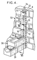
- FIGURE 4 shows a stage in the construction of an extension wall 30 at right angles to the face of an existing wall structure 32 using in one manner the wall plate 8 hereinabove described.
- the wall plate 8 is first securely fixed in a vertical position at the required location to the face of the existing wall structure 32 which is drilled and plugged to receive fixing elements, such as the bolt 34 indicated in the drawing, engaging in the slots 22.
- fixing elements such as the bolt 34 indicated in the drawing
- the wall plate 8 ideally it is positioned so that the transverse axes "T" defining the root ends of the wall tie tongue portions 16 each lie at the level of a mortar joint between adjacent proposed courses of the extension wall and, as indicated in FIGURE 4, these tongue portions initially extend upwards from their root ends.
- the main body portion 10 of the wall plate 8 is set forwards slightly from the face of the wall 32 by the stand-off projections or spacers provided by the raised rim portions 24 around the fixing slots 22, and also by the shallow lip 14.
- each end brick 29 of the extension wall 30 are then laid course-by-course in the usual way with each end brick being butted up to the body portion 10 of the wall plate and aligned by abutting engagement with the retaining guide flange 12 at the one side.
- each wall tie tongue portion 16 Upon reaching each wall tie tongue portion 16, however, the latter is bent outwards so as to extend in a substantially horizontal plane which will lie immediately above an end brick in a course of the extension wall. An example of this is clearly shown in FIGURE 4 in relation to the uppermost brick laid in the extension wall.
- Each integral wall tie tongue 16 is thus sandwiched between different courses of bricks in the extension wall, and it will be appreciated that as the jointing compound or mortar is applied it will surround these tongues and key into the holes or apertures 18.
- each tongue 16 The raised rims 20 of these holes or apertures 18 in each tongue 16 enhances the keying effect and ensures that space is left to accommodate a sufficient thickness of mortar.
- the mortar will also generally penetrate into and key with adjacent holes 15 in the retaining guide flange 12 and into any open adjacent holes or apertures in the body portion 10.
- extension wall 30 is readily built-up in the correct position and orientation with respect to the existing wall structure 32, and is soundly tied in and bonded to the latter without need for any separate wall tie elements, thereby effecting a simplification in the number of parts required id in the construction operation itself.
- the initial shallow inclination of the wall tie tongues 16 with respect to the plane of the body portion 10 enables their free ends readily to be grasped and the tongues can be bent outwards into their "in-use" positions during the operation of building up of the extension wall, after the wall plate has been fixed to the existing wall.
- the courses of the extension wall 30 have a perfectly regular spacing and that the wall plate 8 is positioned such that the transverse axes defining the root ends of the tongues 16 lie at a level of the joint between two adjacent courses.
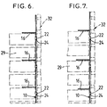
- This is the ideal situation in which the tongues 16 are each bent outwardly about their root ends in order to extend at right angles in the correct position to lie between two adjacent courses of the extension wall and is illustrated in the fragmentary sectional view of FIGURE 6.
- the courses of the extension wall may possibly not be spaced with perfect regularity, perhaps using bricks of different dimensions and/or the wall plate may not be fixed in quite the correct position. Or, the spacing of the tongues 16 may not match the spacing of the bricks.
- the sheet metal of which the wall plate is composed and the form of the tongue portions 16 is such that they can be readily bent not only at their root ends but also at any point in the region adjacent their root ends extending up to at least a third of the way along their length.
- This is in fact indicated in FIGURE 7.
- Tests have shown, somewhat surprisingly, that a strong bond and good stability can be obtained in many cases even if the point at which the tongues are bent lies at least as far as one third along their length. If necessary, the tongues may sometimes even be folded with a double bend. Thereby, irregularities in the vertical spacing of the courses in the extension wall and/or a certain degree of misalignment of the wall plate can be readily accommodated, as schematically indicated for example in FIGURE 7.
- the flange 12 lies on the righthand side of the extension well.
- the flange 12 will be concealed by cladding but this may not be possible if the right-hand side of the extension wall is to be an exposed exterior face, and it may be desired to have the flange 12 on the opposite left-hand side.
- This can readily be arranged simply by turning the wall plate into a reversed position before securing it to the existing wall 32.
- the tongue portions 16 will initially be directed downwards so that each of them needs first to be bent upwards through an angle of more than 90°, possibly even an angle approaching 180°, before laying the bricks of the adjacent course or courses of the extension wall.
- the wall plate 8 is preferably composed of a material such as stainless steel to avoid any corrosion problems and may of course be manufactured in a series of standard lengths which can if necessary be cut, or joined in overlapping aligned relationship, to suit the required height of the extension wall which is to be built. Sheet metal thicknesses in the range of 0.5 mm to 1.00 mm are generally suitable and enable easy bending of the wall tie tongues.
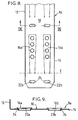
- FIGURES 8 and 9 Two such wall plates arranged in side-by-side mirror image relationship can be used to construct a thick extension wall.
- a wider form of wall plate with a plurality of rows or columns of integral tongue portions will be used.
- FIGURES 8 and 9 one design of such wider form of wall plate 8a is shown in FIGURES 8 and 9. This is basically the same as the wall plate 8 already described but there are two spaced columns or rows of integral wall tie tongue portions 16a and 16b arranged in horizontal pairs as shown, and also horizontal pairs of fixing slots 22a, 22b, are provided between each pair of tongues 16a, 16b. Otherwise the structure corresponds with that already described, corresponding parts being indicated by the same reference numerals, and is used in substantially the same way.
- each adjacent pair again each extend in the same longititudinal direction and each have their root ends aligned in a common transverse plane so that when they are bent up at right angles to the body portion 10 they can both lie in side-by-side relationship in a common transverse plane.
- the body portion of the plates can be formed with a series of dish-like depressions and the apertures for the fixing elements are formed in a substantially flat base portion of such dish-like depressions.
- FIGURES 10 to 14 An example of such modified construction is illustrated in FIGURES 10 to 14.
- the wall plate shown in FIGURES 10 to 14 is basically the same as that described in connection with FIGURES 1 to 3 and the same reference numerals are again used to indicate similar parts.
- the body portion 10 is provided with short transverse slots 22' formed in a substantially flat base 70 of each of a series of dish-like depressions 72 located along the length of the wall plate.
- Each dish-like depression 72 has a shallow peripheral sloping wall 74 and the flat base part 70 is set rearwards from the main plane of the body part of the wall plate by a distance approximately equal to the depth of the edge lip 14 and together with the latter again act as stand-off projections to space the main body portion 10 from the face of the existing wall structure 32 when fixed to the latter.
- the fixing elements used for securing the wall plate to the existing wall will generally be headed screw-threaded fasteners such as the bolt 34 indicated in broken lines in FIGURE 12 and a flat washer 35 will be fitted under the head of this bolt, the dish-like depressions 72 being sufficiently large for such washer (e.g. 30mm diameter washer) to be accommodated wholly therein and to lie against the flat base 70.
- a flat washer 35 will be fitted under the head of this bolt, the dish-like depressions 72 being sufficiently large for such washer (e.g. 30mm diameter washer) to be accommodated wholly therein and to lie against the flat base 70.
- the spacing between the tongues 16 has been shown as corrresponding generally to the depth of two courses of bricks, in fact for use at least in the United Kingdom the spacing will generally be set to correspond to the depth of three courses of standard size bricks or one course of standard size building blocks.
- the wall plates could have a retaining guide flange along each longitudinal edge, and many other detail modifications can be made within the scope of the invention, especially in relation to the arrangement and form of the apertures and of the integral wall tie tongues.
Landscapes
- Engineering & Computer Science (AREA)
- Architecture (AREA)
- Physics & Mathematics (AREA)
- Electromagnetism (AREA)
- Civil Engineering (AREA)
- Structural Engineering (AREA)
- Conveying And Assembling Of Building Elements In Situ (AREA)
- Finishing Walls (AREA)
- Bulkheads Adapted To Foundation Construction (AREA)
- Load-Bearing And Curtain Walls (AREA)
- Piles And Underground Anchors (AREA)
- Working Measures On Existing Buildindgs (AREA)
- Sewage (AREA)
- Surgical Instruments (AREA)
- Farming Of Fish And Shellfish (AREA)
Claims (14)
- Mauerankerelement zur Verwendung beim Bau und zum Anbinden einer aus Ziegelsteinen oder Mauersteinen bestehenden Anschlußwand, die sich winklig nach außen von einer im wesentlichen vertikalen Außenfläche einer vorhandenen Mauerkonstruktion (32) erstreckt, enthaltend eine längliche Platte (8;8a), die einen im wesentlichen flachen Körperabschnitt (10) aufweist und die entlang mindestens eines ihrer Ränder mit einem integralen, aufrechtstehenden, längsverlaufenden Flansch (14) versehen ist, wobei diese Platte (8;8a) bei ihrer Verwendung in einer vertikalen Ausrichtung an der Außenfläche der vorhandenen Mauer (32) befestigt werden kann, um eine Einrichtung zu bilden, die das Positionieren der End-Ziegelsteine oder -Mauersteine (29) der Anschlußwand (30) unterstützt, wenn diese in Anlagestellung mit diesem Körperabschnitt (10) aufgeschichtet werden, der mit dieser Anschlußwand (30) mittels Mauerbinder-Elementen verbindbar ist, die so angeordnet werden können, daß sie sich in das Verbindungsmaterial zwischen benachbarten Lagen der Anschlußwand (30) während ihres Aufbaues erstrecken und in dieses Verbindungsmaterial eingebettet und damit verriegelt werden, um diese Anschlußwand in ihrer Position relativ zu der vorhandenen Mauer zu verankern und damit zu verbinden, dadurch gekennzeichnet, daß mindestens eine Reihe von integralen, länglichen Zungen (16;16a, 16b), die sich in einer Richtung im wesentlichen in Längsrichtung der Platte (8;8a) erstrecken und in Intervallen über die Länge dieser Platte im Abstand voneinander liegen, aus dem Material des Körperabschnittes (10) dieser Platte herausgeformt ist, daß diese Zunge (16;16a,16b) unter einem kleinen Winkel gegenüber der Ebene dieses Körperabschnittes angehoben sind, wodurch die freien Enden dieser Zungen gegenüber der Oberfläche dieses Körperabschnittes (10) der Platte um einen Abstand nach außen ragen, der mindestens so groß ist wie die Dicke des diese Zungen an ihren freien Enden bildenden Materials, derart, daß, nachdem die Platte (8; 8a) vertikal in Position an der Außenfläche der vorhandenen Mauerkonstruktion (32) befestigt ist, diese Zungen (16;16a,16b) bei der Benutzung, leicht ergriffen und nach außen umgebogen werden können, so daß sie im wesentlichen rechtwinklig in einer horizontal Ebene vorspringen, so daß sie sich während des Baus der Anschlußwand in die Fingen zwischen benachbarten Lagen dieser Anschlußwand (30) erstrecken und darin eingebettet und verrieglet werden, um als diese Mauerbinderelemente zu dienen.
- Mauerankerelement nach Anspruch 1, bei dem die Wurzelansätze der Zungen (16;16a,16b) über die Länge der Platte (8;8a) in vorgegebenen, gleichmäßigen Intervallen verteilt sind, die dem erwarteten Abstand oder einem Vielfachen davon zwischen benachbarten Lagen der Anschlußwand (30) entsprechen.
- Mauerankerelement nach Anspruch 1 oder 2, bei dem die Lungen (16;16a,16b) Öffnungen (18) und oder ein divergierend abgeschrägtes Profil aufweisen, so daß sie in das Verbindungsmaterial der Anschlußwand (30) verriegelnd eingeschlossen sind.
- Mauerankerelement nach einem der vorhergehenden Ansprüche, bei dem sämtliche Zungen (16) entlang des Körperabschnittes der Platte (18) in einer einzigen Reihe angeordnet sind, in der sie sich anfänglich in der gleichen allgemeinen Längsrichtung erstrecken.
- Mauerankerelement nach einem der Ansprüche 1 bis 3, bei dem diese Zungen (16a,16b) alle als in Querrichtung ausgerichtete Paare entlang des Körperabschnittes der Platte (8a) angeordnet sind und zwei nebeneinanderliegende Reihen bilden, in denen alle Zungen sich anfänglich in der gleichen, allgemeinen Längsrichtung erstrecken.
- Mauerankerelement nach einem der vorhergehenden Ansprüche, bei dem die Platte (8;8a) aus Metallblech mit einer Dicke im Bereich von 0,5 bis 1,0 mm besteht und die Zungen (16;16a,16b) ausreichend verformbar sind, so daß sie von Hand um eine Querachse in jeder Position zwischen ihren Wurzelansätzen und einem Punkt biegbar sind, der auf mindestens einem Drittel des Weges entlang ihrer Länge liegt.
- Mauerankerelement nach Anspruch 6, bei der Dicke des Metallbleches, aus dem die Platte (8;8a) besteht, etwa 0,7 mm beträgt.
- Mauerankerelement nach einem der vorhergehenden Ansprüche, bei dem die Zungen (16;16a,16b) jeweils eine Länge haben, die mindestens das Fünffache der Breite im Bereich ihres Wurzelansatzes beträgt.
- Mauerankerelement nach einem der vorhergehenden Ansprüche, bei dem der Winkel, unter dem die Zungen (16;16a,16b) in ihrer Ausgangsstellung vor ihrer Benutzung gegenüber der Ebene des Körperabschnittes (10) der Platte angehoben sind, im Bereich von 1° bis 5° liegt.
- Verfahren zum Errichten einer Wand aus Ziegelsteinen oder Mauersteinen als eine Anschlußwand, die sich nach außen in winkeliger Anordnung an eine Außenfläche einer bestehenden Mauerkonstruktion anschließt, indem man ein Mauerankerelement gemäß einem der vorhergehenden Ansprüche an dieser Außenfläche anbringt und daran diese Ankerelementplatte (8;8a) in einer vertikalen Orientierung befestigt, mindestens teilweilse die unteren Lagen der Ziegelsteine oder Mauersteine (29) der Anschlußwand (30) aufschichtet, bis die Oberseite des letzten gegen den Körperabschnitt (10) dieser Platte anliegenden Ziegel- bzw. Mauersteines der verlegten Lage im Höhenbereich des Wurzelansatzes der untersten Zunge (16;16a,16b) dieses Körperabschnittes liegt, diese unterste Zunge nach außen biegt, bis sie sich in eine im wesentliche horizontale Ebene erstreckt, die unmittelbar über der Oberseite dieses Endziegel- oder- Mauersteines (29) der letzten verlegten Lage liegt, Verbindungsmaterial aufträgt und anschließend die nächste Ziegelstein- oder Mauersteinlage verlegt, wodurch diese unterste Zunge (16;16a,16b) in dieses Verbindungsmaterial eingebettet und zwischen den beiden letzten Ziegelstein- oder Mauersteinlagen eingefügt ist, und in der gleichen Weise fortfährt und folgende Lagen verlegt und die jeweils folgende Zunge nach außen umbiegt, wenn die Oberseite des Endziegelsteins oder Endmauersteins der letzten verlegten Lage ein Niveau im Bereich der Höhenstellung von der jeweils folgenden Zunge erreicht, so daß diese Zungen so angeordnet sind, daß sie als die integrierenden Mauerbinderelemente dienen und die Anschlußwand (30) verankern.
- Verfahren zum Errichten einer Anschlußwand nach Anspruch 10, bei dem die Verankerungselementplatte (8;8a) so an der Außenfläche der bestehenden Wand (32) befestigt wird, daß die Zungen (16;16a,16b) in dem Körperabschnitt davon anfänglich nach oben gerichtet sind, bevor sie umgebogen werden.
- Verfahren zum Errichten einer Anschlußwand nach Anspruch 10, bei der die Ankerelementplatte (8;8a) so an der Außenfläche der bestehenden Wand (32) befestigt wird, daß die Zungen (16;16a,16b) in dem Körperabschnitt (10) derselben anfänglich nach unten gerichtet sind, wobei diese Zungen dann um ihre Wurzelansätze jeweils über einen Winkel von mehr als 90° nach oben gebogen werden, so daß sie nach oben gerichtet sind, bevor zumindest jede untere, angrenzende Schicht von Ziegel- oder Mauersteinen (29) der Anschlußwand (30) verlegt wird, und bevor man abschließend jede dieser Zungen zurück nach unten und außen verbiegt, so daß sie sich in einer im wesentlichen horizontalen Ebene erstrecken, um als dieses Mauerbinderelement zu dienen.
- Verfahren zum Errichten einer Anschlußwand nach einem der Ansprüche 10 bis 12, bei dem mindestens einige dieser Zungen (16;16a,16b) bei dem Auswärtsbiegen in im wesentlichen horizontale Ebenen, damit sie als diese Mauerbinderelemente dienen können, um eine Querachse verbogen werden, die im Abstand von ihren jeweiligen Wurzelansätzen liegt.
- Verfahren zum Errichten einer Anschlußwand nach Anspruch (13), bei dem diese Querachsen, um die mindestens einige dieser Zungen (16;16a,16b) gebogen werden, in einem Bereich der jeweiligen Zungen liegen, der zwischen dem Wurzelansatz derselben und einem Punkt liegt, der sich auf einem Drittel des Weges entlang der Länge dieser jeweiligen Zunge befindet und dichter an diesem Punkt als an diesem Wurzelansatz liegt.
Applications Claiming Priority (6)
| Application Number | Priority Date | Filing Date | Title |
|---|---|---|---|
| GB858510321A GB8510321D0 (en) | 1985-04-23 | 1985-04-23 | Wall plate |
| GB8510321 | 1985-04-23 | ||
| GB8602103 | 1986-01-29 | ||
| GB868602103A GB8602103D0 (en) | 1986-01-29 | 1986-01-29 | Wall plate |
| GB868604576A GB8604576D0 (en) | 1986-02-25 | 1986-02-25 | Wall construction device |
| GB8604576 | 1986-02-25 |
Publications (3)
| Publication Number | Publication Date |
|---|---|
| EP0199595A2 EP0199595A2 (de) | 1986-10-29 |
| EP0199595A3 EP0199595A3 (en) | 1987-05-27 |
| EP0199595B1 true EP0199595B1 (de) | 1995-03-22 |
Family
ID=27262659
Family Applications (1)
| Application Number | Title | Priority Date | Filing Date |
|---|---|---|---|
| EP86303055A Expired - Lifetime EP0199595B1 (de) | 1985-04-23 | 1986-04-23 | Verbundanker für Mauerwerk |
Country Status (5)
| Country | Link |
|---|---|
| EP (1) | EP0199595B1 (de) |
| AT (1) | ATE120249T1 (de) |
| AU (1) | AU587247B2 (de) |
| DE (1) | DE3650275T2 (de) |
| GB (1) | GB2174432B (de) |
Cited By (24)
| Publication number | Priority date | Publication date | Assignee | Title |
|---|---|---|---|---|
| US8739485B2 (en) | 2012-06-28 | 2014-06-03 | Mitek Holdings, Inc. | Low profile pullout resistant pintle and anchoring system utilizing the same |
| US8800241B2 (en) | 2012-03-21 | 2014-08-12 | Mitek Holdings, Inc. | Backup wall reinforcement with T-type anchor |
| US8833003B1 (en) | 2013-03-12 | 2014-09-16 | Columbia Insurance Company | High-strength rectangular wire veneer tie and anchoring systems utilizing the same |
| US8839581B2 (en) | 2012-09-15 | 2014-09-23 | Mitek Holdings, Inc. | High-strength partially compressed low profile veneer tie and anchoring system utilizing the same |
| US8839587B2 (en) | 2012-03-14 | 2014-09-23 | Columbia Insurance Company | Mounting arrangement for panel veneer structures |
| US8844229B1 (en) * | 2013-03-13 | 2014-09-30 | Columbia Insurance Company | Channel anchor with insulation holder and anchoring system using the same |
| US8863460B2 (en) | 2013-03-08 | 2014-10-21 | Columbia Insurance Company | Thermally coated wall anchor and anchoring systems with in-cavity thermal breaks |
| US8881488B2 (en) | 2012-12-26 | 2014-11-11 | Mitek Holdings, Inc. | High-strength ribbon loop anchors and anchoring systems utilizing the same |
| US8898980B2 (en) | 2012-09-15 | 2014-12-02 | Mitek Holdings, Inc. | Pullout resistant pintle and anchoring system utilizing the same |
| US8904727B1 (en) | 2013-10-15 | 2014-12-09 | Columbia Insurance Company | High-strength vertically compressed veneer tie anchoring systems utilizing and the same |
| US8904726B1 (en) | 2013-06-28 | 2014-12-09 | Columbia Insurance Company | Vertically adjustable disengagement prevention veneer tie and anchoring system utilizing the same |
| US8904730B2 (en) | 2012-03-21 | 2014-12-09 | Mitek Holdings, Inc. | Thermally-isolated anchoring systems for cavity walls |
| US8910445B2 (en) | 2013-03-13 | 2014-12-16 | Columbia Insurance Company | Thermally isolated anchoring system |
| US8978330B2 (en) | 2013-07-03 | 2015-03-17 | Columbia Insurance Company | Pullout resistant swing installation tie and anchoring system utilizing the same |
| US8978326B2 (en) | 2013-03-12 | 2015-03-17 | Columbia Insurance Company | High-strength partition top anchor and anchoring system utilizing the same |
| US9038351B2 (en) | 2013-03-06 | 2015-05-26 | Columbia Insurance Company | Thermally coated wall anchor and anchoring systems with in-cavity thermal breaks for cavity walls |
| US9038350B2 (en) | 2013-10-04 | 2015-05-26 | Columbia Insurance Company | One-piece dovetail veneer tie and wall anchoring system with in-cavity thermal breaks |
| US9121169B2 (en) | 2013-07-03 | 2015-09-01 | Columbia Insurance Company | Veneer tie and wall anchoring systems with in-cavity ceramic and ceramic-based thermal breaks |
| US9140001B1 (en) | 2014-06-24 | 2015-09-22 | Columbia Insurance Company | Thermal wall anchor |
| US9273461B1 (en) | 2015-02-23 | 2016-03-01 | Columbia Insurance Company | Thermal veneer tie and anchoring system |
| US9334646B2 (en) | 2014-08-01 | 2016-05-10 | Columbia Insurance Company | Thermally-isolated anchoring systems with split tail veneer tie for cavity walls |
| US10202754B2 (en) | 2015-12-04 | 2019-02-12 | Columbia Insurance Company | Thermal wall anchor |
| USD846973S1 (en) | 2015-09-17 | 2019-04-30 | Columbia Insurance Company | High-strength partition top anchor |
| US10407892B2 (en) | 2015-09-17 | 2019-09-10 | Columbia Insurance Company | High-strength partition top anchor and anchoring system utilizing the same |
Families Citing this family (11)
| Publication number | Priority date | Publication date | Assignee | Title |
|---|---|---|---|---|
| GB2227777A (en) * | 1989-02-02 | 1990-08-08 | David John Landeg | Reinforcement to brickwork or blockwork retaining walls |
| GB2229465A (en) * | 1989-03-21 | 1990-09-26 | James Savage Pritchard | Plaster panels |
| AT403596B (de) * | 1989-06-19 | 1998-03-25 | Eggert Heinz | Gebäudewand-verkleidung |
| GB9017301D0 (en) * | 1990-08-07 | 1990-09-19 | Young John K | Construction joint former |
| AU688443B2 (en) * | 1994-03-09 | 1998-03-12 | Abey Australia Pty Ltd | Improvements in brick ties |
| DE102005026797A1 (de) * | 2005-06-10 | 2006-12-14 | Wahls, Manfred, Dipl.-Ing. | Dämmstoff-Verbundwand |
| GB2443485B (en) * | 2006-11-02 | 2011-09-14 | Victor Joseph Wigley | Insulated structural tie for external masonry wall and internal abutting wall |
| CN101736814B (zh) * | 2009-12-15 | 2012-05-23 | 浙江宝业建设集团有限公司 | 建筑墙体抗震构造柱连接件及其施工方法 |
| US10738476B2 (en) * | 2018-04-29 | 2020-08-11 | Reza Moghimi | Support structure for installing thin bricks |
| CN112025970A (zh) * | 2020-08-14 | 2020-12-04 | 中建科技成都有限公司 | 一种构造柱拼接块的加工装置及构造柱施工方法 |
| CN119981473B (zh) * | 2025-04-15 | 2025-11-21 | 中国建筑第五工程局有限公司 | 一种市政工程铺装对缝装置 |
Family Cites Families (5)
| Publication number | Priority date | Publication date | Assignee | Title |
|---|---|---|---|---|
| GB940664A (en) * | 1961-02-23 | 1963-10-30 | Ray Edward Omholt | Wooden floors |
| GB1010933A (en) * | 1962-06-14 | 1965-11-24 | Milton Oswald Hemming | Improvements in or relating to means for providing anchorage points in ceilings |
| GB1575501A (en) * | 1976-11-05 | 1980-09-24 | Ellidge A | Tie means for brick walls |
| ZA78948B (en) * | 1978-02-17 | 1979-09-26 | R Geraghty | A device for use in building |
| GB1604941A (en) * | 1978-05-26 | 1981-12-16 | Furr D | Wall construction method |
-
1986
- 1986-04-23 AU AU56535/86A patent/AU587247B2/en not_active Ceased
- 1986-04-23 GB GB08609949A patent/GB2174432B/en not_active Expired
- 1986-04-23 AT AT86303055T patent/ATE120249T1/de not_active IP Right Cessation
- 1986-04-23 EP EP86303055A patent/EP0199595B1/de not_active Expired - Lifetime
- 1986-04-23 DE DE3650275T patent/DE3650275T2/de not_active Expired - Fee Related
Cited By (33)
| Publication number | Priority date | Publication date | Assignee | Title |
|---|---|---|---|---|
| US8839587B2 (en) | 2012-03-14 | 2014-09-23 | Columbia Insurance Company | Mounting arrangement for panel veneer structures |
| US8800241B2 (en) | 2012-03-21 | 2014-08-12 | Mitek Holdings, Inc. | Backup wall reinforcement with T-type anchor |
| US9732514B2 (en) | 2012-03-21 | 2017-08-15 | Columbia Insurance Company | Backup wall reinforcement with T-type anchor |
| US9273460B2 (en) | 2012-03-21 | 2016-03-01 | Columbia Insurance Company | Backup wall reinforcement with T-type anchor |
| US8904730B2 (en) | 2012-03-21 | 2014-12-09 | Mitek Holdings, Inc. | Thermally-isolated anchoring systems for cavity walls |
| US8739485B2 (en) | 2012-06-28 | 2014-06-03 | Mitek Holdings, Inc. | Low profile pullout resistant pintle and anchoring system utilizing the same |
| US8839581B2 (en) | 2012-09-15 | 2014-09-23 | Mitek Holdings, Inc. | High-strength partially compressed low profile veneer tie and anchoring system utilizing the same |
| US8898980B2 (en) | 2012-09-15 | 2014-12-02 | Mitek Holdings, Inc. | Pullout resistant pintle and anchoring system utilizing the same |
| US8881488B2 (en) | 2012-12-26 | 2014-11-11 | Mitek Holdings, Inc. | High-strength ribbon loop anchors and anchoring systems utilizing the same |
| US9340968B2 (en) | 2012-12-26 | 2016-05-17 | Columbia Insurance Company | Anchoring system having high-strength ribbon loop anchor |
| US9624659B2 (en) | 2013-03-06 | 2017-04-18 | Columbia Insurance Company | Thermally coated wall anchor and anchoring systems with in-cavity thermal breaks for cavity walls |
| US9038351B2 (en) | 2013-03-06 | 2015-05-26 | Columbia Insurance Company | Thermally coated wall anchor and anchoring systems with in-cavity thermal breaks for cavity walls |
| US8863460B2 (en) | 2013-03-08 | 2014-10-21 | Columbia Insurance Company | Thermally coated wall anchor and anchoring systems with in-cavity thermal breaks |
| US9080327B2 (en) | 2013-03-08 | 2015-07-14 | Columbia Insurance Company | Thermally coated wall anchor and anchoring systems with in-cavity thermal breaks |
| USD756762S1 (en) | 2013-03-12 | 2016-05-24 | Columbia Insurance Company | High-strength partition top anchor |
| US8978326B2 (en) | 2013-03-12 | 2015-03-17 | Columbia Insurance Company | High-strength partition top anchor and anchoring system utilizing the same |
| US8833003B1 (en) | 2013-03-12 | 2014-09-16 | Columbia Insurance Company | High-strength rectangular wire veneer tie and anchoring systems utilizing the same |
| US8910445B2 (en) | 2013-03-13 | 2014-12-16 | Columbia Insurance Company | Thermally isolated anchoring system |
| US8844229B1 (en) * | 2013-03-13 | 2014-09-30 | Columbia Insurance Company | Channel anchor with insulation holder and anchoring system using the same |
| US8904726B1 (en) | 2013-06-28 | 2014-12-09 | Columbia Insurance Company | Vertically adjustable disengagement prevention veneer tie and anchoring system utilizing the same |
| US8978330B2 (en) | 2013-07-03 | 2015-03-17 | Columbia Insurance Company | Pullout resistant swing installation tie and anchoring system utilizing the same |
| US9121169B2 (en) | 2013-07-03 | 2015-09-01 | Columbia Insurance Company | Veneer tie and wall anchoring systems with in-cavity ceramic and ceramic-based thermal breaks |
| US9038350B2 (en) | 2013-10-04 | 2015-05-26 | Columbia Insurance Company | One-piece dovetail veneer tie and wall anchoring system with in-cavity thermal breaks |
| US8904727B1 (en) | 2013-10-15 | 2014-12-09 | Columbia Insurance Company | High-strength vertically compressed veneer tie anchoring systems utilizing and the same |
| US9140001B1 (en) | 2014-06-24 | 2015-09-22 | Columbia Insurance Company | Thermal wall anchor |
| US9758958B2 (en) | 2014-06-24 | 2017-09-12 | Columbia Insurance Company | Thermal wall anchor |
| US9334646B2 (en) | 2014-08-01 | 2016-05-10 | Columbia Insurance Company | Thermally-isolated anchoring systems with split tail veneer tie for cavity walls |
| US9273461B1 (en) | 2015-02-23 | 2016-03-01 | Columbia Insurance Company | Thermal veneer tie and anchoring system |
| USD846973S1 (en) | 2015-09-17 | 2019-04-30 | Columbia Insurance Company | High-strength partition top anchor |
| US10407892B2 (en) | 2015-09-17 | 2019-09-10 | Columbia Insurance Company | High-strength partition top anchor and anchoring system utilizing the same |
| USD882383S1 (en) | 2015-09-17 | 2020-04-28 | Columbia Insurance Company | High-strength partition top anchor |
| USD937669S1 (en) | 2015-09-17 | 2021-12-07 | Hohmann & Barnard, Inc. | High-strength partition top anchor |
| US10202754B2 (en) | 2015-12-04 | 2019-02-12 | Columbia Insurance Company | Thermal wall anchor |
Also Published As
| Publication number | Publication date |
|---|---|
| ATE120249T1 (de) | 1995-04-15 |
| GB2174432B (en) | 1988-10-26 |
| AU587247B2 (en) | 1989-08-10 |
| DE3650275T2 (de) | 1995-08-24 |
| DE3650275D1 (de) | 1995-04-27 |
| EP0199595A3 (en) | 1987-05-27 |
| EP0199595A2 (de) | 1986-10-29 |
| AU5653586A (en) | 1986-10-30 |
| GB2174432A (en) | 1986-11-05 |
| GB8609949D0 (en) | 1986-05-29 |
Similar Documents
| Publication | Publication Date | Title |
|---|---|---|
| EP0199595A2 (de) | Verbundanker für Mauerwerk | |
| US4922680A (en) | Systems and methods for connecting masonry veneer to structural support substrates | |
| US4669235A (en) | Spacing and support construction member | |
| CA2054503C (en) | Fence post | |
| US7469511B2 (en) | Masonry anchoring system | |
| US5150553A (en) | Holdown strap | |
| US4698947A (en) | Concrete wall form tie system | |
| US7415804B2 (en) | Isulated concrete form having welded wire form tie | |
| US4168596A (en) | Standing seam metal roof structure and method of assembly | |
| US6237300B1 (en) | Wall stud connectors | |
| US2005030A (en) | Veneer fastening means | |
| US20080092472A1 (en) | Adjustable masonry anchor assembly for use with insulating concrete form systems | |
| US20020014048A1 (en) | Tie for forms for pouring concrete | |
| US6629393B2 (en) | Masonry reinforcing tie | |
| US4617770A (en) | Nailerless roof edge, framing structure and building panel mounting assembly | |
| US5299403A (en) | Insulation fastener | |
| US3782058A (en) | Tying devices for tying wooden members to composite brick and masonry walls | |
| US2003996A (en) | Veneer wall construction | |
| US3389525A (en) | Prefabricated wall nail-tie assembly | |
| EP1668199B1 (de) | Vorrichtung und verfahren zur befestigung einer isolierplatte in einer hohlwand | |
| EP0118176A2 (de) | Hohlwandanker, Konstruktionsverfahren und Hohlwandkonstruktion | |
| US5860261A (en) | Building block retainer apparatus | |
| EP0357279B1 (de) | Unterstützung für Gipskartonplatten und Dachdämmung | |
| WO2003093594A1 (en) | Framework and hold down connector | |
| JP3570560B2 (ja) | デッキプレート、役物デッキプレート及び調整プレート |
Legal Events
| Date | Code | Title | Description |
|---|---|---|---|
| PUAI | Public reference made under article 153(3) epc to a published international application that has entered the european phase |
Free format text: ORIGINAL CODE: 0009012 |
|
| AK | Designated contracting states |
Kind code of ref document: A2 Designated state(s): AT BE CH DE FR GB IT LI LU NL SE |
|
| PUAL | Search report despatched |
Free format text: ORIGINAL CODE: 0009013 |
|
| AK | Designated contracting states |
Kind code of ref document: A3 Designated state(s): AT BE CH DE FR GB IT LI LU NL SE |
|
| 17P | Request for examination filed |
Effective date: 19871125 |
|
| 17Q | First examination report despatched |
Effective date: 19891030 |
|
| ITF | It: translation for a ep patent filed | ||
| GRAA | (expected) grant |
Free format text: ORIGINAL CODE: 0009210 |
|
| AK | Designated contracting states |
Kind code of ref document: B1 Designated state(s): AT BE CH DE FR IT LI LU NL SE |
|
| REF | Corresponds to: |
Ref document number: 120249 Country of ref document: AT Date of ref document: 19950415 Kind code of ref document: T |
|
| ET | Fr: translation filed | ||
| REF | Corresponds to: |
Ref document number: 3650275 Country of ref document: DE Date of ref document: 19950427 |
|
| PLBE | No opposition filed within time limit |
Free format text: ORIGINAL CODE: 0009261 |
|
| STAA | Information on the status of an ep patent application or granted ep patent |
Free format text: STATUS: NO OPPOSITION FILED WITHIN TIME LIMIT |
|
| 26N | No opposition filed | ||
| PGFP | Annual fee paid to national office [announced via postgrant information from national office to epo] |
Ref country code: CH Payment date: 19970411 Year of fee payment: 12 |
|
| PGFP | Annual fee paid to national office [announced via postgrant information from national office to epo] |
Ref country code: SE Payment date: 19970416 Year of fee payment: 12 |
|
| PGFP | Annual fee paid to national office [announced via postgrant information from national office to epo] |
Ref country code: BE Payment date: 19970428 Year of fee payment: 12 |
|
| PGFP | Annual fee paid to national office [announced via postgrant information from national office to epo] |
Ref country code: FR Payment date: 19970429 Year of fee payment: 12 Ref country code: AT Payment date: 19970429 Year of fee payment: 12 |
|
| PGFP | Annual fee paid to national office [announced via postgrant information from national office to epo] |
Ref country code: NL Payment date: 19970430 Year of fee payment: 12 |
|
| PGFP | Annual fee paid to national office [announced via postgrant information from national office to epo] |
Ref country code: DE Payment date: 19970627 Year of fee payment: 12 |
|
| PGFP | Annual fee paid to national office [announced via postgrant information from national office to epo] |
Ref country code: LU Payment date: 19970703 Year of fee payment: 12 |
|
| PG25 | Lapsed in a contracting state [announced via postgrant information from national office to epo] |
Ref country code: LU Free format text: LAPSE BECAUSE OF NON-PAYMENT OF DUE FEES Effective date: 19980423 Ref country code: AT Free format text: LAPSE BECAUSE OF NON-PAYMENT OF DUE FEES Effective date: 19980423 |
|
| PG25 | Lapsed in a contracting state [announced via postgrant information from national office to epo] |
Ref country code: SE Free format text: LAPSE BECAUSE OF NON-PAYMENT OF DUE FEES Effective date: 19980424 |
|
| PG25 | Lapsed in a contracting state [announced via postgrant information from national office to epo] |
Ref country code: LI Free format text: LAPSE BECAUSE OF NON-PAYMENT OF DUE FEES Effective date: 19980430 Ref country code: FR Free format text: THE PATENT HAS BEEN ANNULLED BY A DECISION OF A NATIONAL AUTHORITY Effective date: 19980430 Ref country code: CH Free format text: LAPSE BECAUSE OF NON-PAYMENT OF DUE FEES Effective date: 19980430 Ref country code: BE Free format text: LAPSE BECAUSE OF NON-PAYMENT OF DUE FEES Effective date: 19980430 |
|
| BERE | Be: lapsed |
Owner name: THE EXPANDED METAL CY LTD Effective date: 19980430 |
|
| PG25 | Lapsed in a contracting state [announced via postgrant information from national office to epo] |
Ref country code: NL Free format text: LAPSE BECAUSE OF NON-PAYMENT OF DUE FEES Effective date: 19981101 |
|
| REG | Reference to a national code |
Ref country code: CH Ref legal event code: PL |
|
| NLV4 | Nl: lapsed or anulled due to non-payment of the annual fee |
Effective date: 19981101 |
|
| EUG | Se: european patent has lapsed |
Ref document number: 86303055.7 |
|
| PG25 | Lapsed in a contracting state [announced via postgrant information from national office to epo] |
Ref country code: DE Free format text: LAPSE BECAUSE OF NON-PAYMENT OF DUE FEES Effective date: 19990202 |
|
| REG | Reference to a national code |
Ref country code: FR Ref legal event code: ST |
|
| PG25 | Lapsed in a contracting state [announced via postgrant information from national office to epo] |
Ref country code: IT Free format text: LAPSE BECAUSE OF NON-PAYMENT OF DUE FEES;WARNING: LAPSES OF ITALIAN PATENTS WITH EFFECTIVE DATE BEFORE 2007 MAY HAVE OCCURRED AT ANY TIME BEFORE 2007. THE CORRECT EFFECTIVE DATE MAY BE DIFFERENT FROM THE ONE RECORDED. Effective date: 20050423 |
|
| APAH | Appeal reference modified |
Free format text: ORIGINAL CODE: EPIDOSCREFNO |