EP0199179B1 - Drain recovery system for condensate feedwater system of nuclear power plant - Google Patents
Drain recovery system for condensate feedwater system of nuclear power plant Download PDFInfo
- Publication number
- EP0199179B1 EP0199179B1 EP86104801A EP86104801A EP0199179B1 EP 0199179 B1 EP0199179 B1 EP 0199179B1 EP 86104801 A EP86104801 A EP 86104801A EP 86104801 A EP86104801 A EP 86104801A EP 0199179 B1 EP0199179 B1 EP 0199179B1
- Authority
- EP
- European Patent Office
- Prior art keywords
- drain
- condensate
- level
- feedwater
- tank
- Prior art date
- Legal status (The legal status is an assumption and is not a legal conclusion. Google has not performed a legal analysis and makes no representation as to the accuracy of the status listed.)
- Expired - Lifetime
Links
Images


Classifications
-
- G—PHYSICS
- G21—NUCLEAR PHYSICS; NUCLEAR ENGINEERING
- G21D—NUCLEAR POWER PLANT
- G21D5/00—Arrangements of reactor and engine in which reactor-produced heat is converted into mechanical energy
- G21D5/04—Reactor and engine not structurally combined
- G21D5/08—Reactor and engine not structurally combined with engine working medium heated in a heat exchanger by the reactor coolant
- G21D5/12—Liquid working medium vaporised by reactor coolant
-
- G—PHYSICS
- G21—NUCLEAR PHYSICS; NUCLEAR ENGINEERING
- G21D—NUCLEAR POWER PLANT
- G21D1/00—Details of nuclear power plant
- G21D1/02—Arrangements of auxiliary equipment
-
- Y—GENERAL TAGGING OF NEW TECHNOLOGICAL DEVELOPMENTS; GENERAL TAGGING OF CROSS-SECTIONAL TECHNOLOGIES SPANNING OVER SEVERAL SECTIONS OF THE IPC; TECHNICAL SUBJECTS COVERED BY FORMER USPC CROSS-REFERENCE ART COLLECTIONS [XRACs] AND DIGESTS
- Y02—TECHNOLOGIES OR APPLICATIONS FOR MITIGATION OR ADAPTATION AGAINST CLIMATE CHANGE
- Y02E—REDUCTION OF GREENHOUSE GAS [GHG] EMISSIONS, RELATED TO ENERGY GENERATION, TRANSMISSION OR DISTRIBUTION
- Y02E30/00—Energy generation of nuclear origin
-
- Y—GENERAL TAGGING OF NEW TECHNOLOGICAL DEVELOPMENTS; GENERAL TAGGING OF CROSS-SECTIONAL TECHNOLOGIES SPANNING OVER SEVERAL SECTIONS OF THE IPC; TECHNICAL SUBJECTS COVERED BY FORMER USPC CROSS-REFERENCE ART COLLECTIONS [XRACs] AND DIGESTS
- Y02—TECHNOLOGIES OR APPLICATIONS FOR MITIGATION OR ADAPTATION AGAINST CLIMATE CHANGE
- Y02E—REDUCTION OF GREENHOUSE GAS [GHG] EMISSIONS, RELATED TO ENERGY GENERATION, TRANSMISSION OR DISTRIBUTION
- Y02E30/00—Energy generation of nuclear origin
- Y02E30/30—Nuclear fission reactors
Definitions
- the present invention relates to a drain recovery system for the condensate feedwater system of a nuclear power plant and, more particularly, to a drain recovery system in which drains from feedwater heaters of the condensate feedwater system is collected and recovered to the condenstae feedwater system.
- a drain recovery system for the condensate feedwater system of a nuclear power plant has been known in which the feedwater heater drains stored in a drain tank are pumped-up by drain pumps to be injected into the condensate feedwater system at a predetermined portion thereof for recovery of the drains.
- PWR pressurized water reactor
- BWR boiling water reactor
- the pressure of the portion of the condensate feedwater system at which the feedwater heater drain is injected thereinto varies significantly depending on the level of the load of the plant. More specifically, when the plant load is comparatively in a low level, the flow rate of the feedwater is correspondingly small, which in turn reduces the pressure drop in the condensate feedwater system and also serves to increase the delivery head of the condensate pumps, so that the pressure in the portion of the condensate feedwater system at which the collected drain is injected thereinto is increased. This means that the required delivery head of the drain pumps is largely changed depending on the level of the load.
- drain pumps delivery head required for the drain pumps is large at the low load level and small at the high load level, so that the drain pumps must satisfy a wide range of the required delivery head.
- the drain pumping-up recovery system incorporates a water purifier through which the drain is purified before it is injected into the condensate feedwater system.
- the provision of the water purifier increases the pressure drop, which necessitates a further increase in the drain pump capacity and further complication of the design of the drain pumps. It might be desired that not only the high-pressure feedwater heater drain but also the low-pressure feedwater heater drain, are pumped-up and injected into the condensate feedwater system.
- the known drain pumping-up recovery system encounters a problem that, when the drain pumps malfunction and trip, the flow rate of the drain injected into the condensate feedwater system and, hence, the flow rate of the feedwater supplied to the nuclear reactor becomes insufficient, and thus the plant might be scramed as a whole.
- the drain level in the drain tank is raised so that the flow of the drain from the high-pressure feedwater heater into the drain tank is impeded to cause a risk of a rise in the drain level in the high-pressure feedwater heater, which in turn may cause a reverse flow of the drains into the high-pressure turbine, with a result that the turbine is damaged.
- DE-A 3 330 012 discloses a drain recovery system for, the condensate feedwater system of a nuclear power plant in accordance with the first part of claim 1, in which the condensate from the condenser is heated and then applied to a tank in which this condensate is mixed with the condensate generated by vapor extracted from a high-pressure turbine. In this system, all feedwater for the power plant is supplied to the tank which must therefore have a large capacity.
- the steam generated in a nuclear reactor 1 is introduced into a high-pressure turbine 2 and then into a low-pressure turbine 3 so as to drive the turbines.
- the steam which has been used in the low-pressure turbine is cascaded down in a condenser 4 to become a condensate, and the condensate is fed back as a feedwater to the nuclear reactor 1 through a condensate feedwater system 50.
- the condensate in the condenser 4 is sucked into and boosted by low-pressure condensate pumps 5 and is purified through a condensate filter 6 and a condensate desalination device 7 to a degree sufficient for the condensate to be able to be fed into the nuclear reactor.
- the condensate thus purified is sucked into and boosted by high-pressure condensate pumps 8 and is delivered to a low-pressure feedwater heater 9 in which the condensate is heated by the steam extracted from the low-pressure turbine 3.
- the heated condensate is sucked into and boosted by feedwater pumps 10 and is delivered to a high-pressure feedwater heater 11 in which the condensate is further heated by the steam extracted from the high-pressure turbine 2 before supplied to the nuclear reactor 1 as the feedwater.
- the high-pressure turbine extracted steam which has heated the condensate in the high-pressure feedwater heater 11 is condensed into a drain as a result of the heat exchange with the condensate.
- the drain is introduced into the low-pressure feedwater heater 9 by the pressure differential therebetween so as to heat the condensate in the low-pressure feedwater heater 9.
- the extracted steam which has heated the condensate in the low-pressure feedwater heater 9 is also condensed into a drain, which is sent to a drain recovery system 51 together with the drain from the high-pressure feedwater heater which has heated the condensate in the low-pressure feedwater heater 9.
- the drain recovery system 51 has a drain pumping-up recovery system 52 including a drain tank 12 for storing the feedwater heater drains, and a drain level control device 53 for maintaining the drain level in the drain tank 12 at a predetermined position.
- the drain tank 12 of the drain pumping-up recovery system 52 is connected to the low-pressure feedwater heater 9 so that the drain in the low-pressure feedwater heater 9 can be introduced into the drain tank 12 by the pressure differential therebetween.
- the drain recovery system 51 also has drain pumps 13 which suck up the drains in the drain tank 12 and delivers the same to a drain purifier 15 through a control valve 14.
- the purified drain from the drain purifier 15 is injected, by the operation of the drain pumps 13, into the condensate feedwater system 50 at a predetermined portion 16 thereof positioned on the inlet side of the high-pressure feedwater pump 8.
- a minimum flow pipe 13a is connected between the outlet side of the drain pump 13 and the drain tank 12.
- the drain discharged from the drain pumps 13 is returned to the drain tank 12 through the minimum flow pipe 13a, thereby securing the minimum flow rate necessary for the continuous operation of the drain pumps 13.
- the drain level in the drain tank 12 is detected by a drain level detector 17 and is maintained constant by the operation of the control valve 14. With this arrangement, the flow rate of the drains injected into the condensate feedwater system at the portion 16 thereof is equalized to the flow rate of the drains introduced into the drain tank 12, so that the required flow rate of the feedwater supplied to the nuclear reactor is ensured at the portion 16.
- the flow rate of the feedwater supplied to the nuclear reactor 1 is controlled by means of a speed controller (not shown) for the turbine which drives the feedwater pumps 10, and also by a flow-rate control valve (not shown) provided on the outlet side of the feedwater pumps 10 as the level of the water in the nuclear reactor 1 is detected by a water level detector (not shown).
- the drain level control device 53 has a conduit 22 through which a drain outlet pipe 18 is connected to the condenser 4.
- the conduit 22 is provided with a second control valve 23.
- the drain level control device 53 further has a load level detector 24 which detects the level of the load of the plant, a trip detector 25 for detecting a trip of any one of the drain pumps 13, and a change-over device 26 responsive to the output signals from the load level detector 24 and the trip detector 25 for selectively transferring the output signal from the drain level detector 17 to either one of the first control valve 14 or the second control valve 23.
- the drain level detector 17 is adapted to generate a drain level signal when the drain level in the drain tank 12 should exceed a predetermined position.
- the load level detector 24 detects the load level of the plant by detecting the flow rate of the feedwater supplied to the nuclear reactor 1 or by detecting the load imposed on an electric generator not shown for example. When the load level of the plant is low, the load level detector 24 produces a low load signal.
- the trip detector 25 detects a trip of any one of the drain pumps 13 by sensing the delivery pressure of each drain pump 13, and produces a trip signal upon detection of the trip.
- the change-over device 26 transfers the drain level signal from the drain level detector 17 to the first control valve 14 when neither the low load signal nor the trip signal is outputted from the load level detector 24 and the trip detector 25, and it transfers the drain level signal to the second control valve 23 when at least one of the low level signal and the trip signal is outputted.
- drain recovery system 51 The operation of the drain recovery system 51 will be explained hereinunder.
- the drain level detector 17 produces a drain level signal when the drain level in the drain tank 12 should exceed the predetermined position.
- the change-over device 26 transfers the drain level signal to the first control valve 14, thereby opening the same. Consequently, the drains in the drain tank 12 pumped up by the drain pumps 13 are delivered to the drain purifier 15 through the control valve 14 and are injected into the condensate feedwater system 50 at the portion 16 thereof for recovery therein.
- the drain level detector 17 stops the delivery of the drain level signal so that the control valve 14 is closed.
- the drain pumps 13 continue to operate so that the drains delivered by the drain pumps are recirculated to the drain tank 12 through the minimum flow pipe 13a.
- the drain pumps 13 may be designed such that they are automatically started and stopped in accordance with the operation of the control valve 14.
- the load detector 24 When the load level of the plant is low, e.g., below 50%, as in the time of start-up of the plant, the load detector 24 produces the low load signal, so that the change-over device 26 operates to transfer the drain level signal to the second control valve 23 in response to the low load signal from the load level detector 24. Therefore, when the drain level in the drain tank 12 should exceed the predetermined position, the drain level detector 17 produces the drain level signal which is transferred to the second control valve 23 through the change-over device 26, so that the second control valve 23 is opened. As a result, since a high vacuum has been established in the condenser 4, the drains in the drain tank 12 are sucked into the condenser 4 through the conduit 22 by the pressure differential. At this time, the first control valve 14 is closed since the drain level signal is not transferred thereto, so that the drain pump 13 operates to recirculate the drains through the minimum flow pipe 13a as explained below.
- the drain pumps 13 are required to have a delivery head which equals to the sum of the pressure in the portion 16 of the condensate feedwater system 50 at which the drains are injected thereinto and the pressure drop at the delivery side of the drain pumps 13. According to the invention, it is possible to reduce the required delivery head of the drain pumps 13 by virtue of the operation of the drain level control device 53, as will be understood from the following description.
- Fig. 3 shows the change in the pressure in the portion 16 of the condensate feedwater system at which the drains are injected thereinto. It will be seen that the pressure at the portion 16 is comparatively high when the load level of the plant is low. This is attributable to the facts that at the low load level of the plant, the pressure drop along the condensate feedwater system 50 is small due to the small flow rate of feedwater and also the delivery head of the condensate pump 5 is high due to the small flow rate of feedwater.
- Fig. 4- shows the pressure drop at the delivery side of the drain pumps 13. It will be seen that the pressure drop is increased as the load level of the plant is increased. This is attributable to the fact that the amount of the drains from the feedwater heaters is increased with the increase in the load level of the plant. It will also be noted that the drain purifier 15 is contaminated day by day, and as the contamination of the drain purifier 15 becomes heavy, the pressure drop becomes serious even during low-load operation of the nuclear reactor in which the amount of drains is comparatively small.
- Fig. 5 shows the sum of the pressure shown in Fig. 3 in the portion 16 of the condensate feedwater system 50 at which the drains are injected thereinto and the pressure drop shown in Fig. 4 experienced at the outlet side of the drain pumps 13. It will be seen that the delivery head required for injecting the drains at the portion 16 is increased as the load level becomes lower. It is assumed here that the drain level control device 53 is not provided so that the drain pumps 13 must deliver the drains to the portion 16 of the condensate feedwater system 50 over the entire range of load levels of the plant. In such a case, a large difference in the required delivery head is observed since the required delivery head at the low load level of the plant is high while the required delivery head at the high load level of the plant is low. Thus, the drain pumps must satisfy a wide range of the required delivery head. This complicates the specification of the drain pumps and makes it difficult to design the drain pump system.
- the drain level control device 53 opens the second control valve 23 so as to maintain the drain level in the drain tank 12 constant. Therefore, when the plant operates with a low load level such as 50% or below, it is not necessary to pump-up and deliver the drains to the condensate feedwater system 50 by the drain pumps 13. It is, therefore, possible to reduce the delivery head required for the drain pumps 13 and, hence, to reduce the capacity of the drain pumps 13, which makes it possible to use smaller pumps as the drain pumps, while simplifying the design of the drain pumps system. In addition, the required flow rate of the feedwater supplied to the nuclear reactor 1 is maintained so that any risk of scram of the plant is avoided, as well as any risk of damage of the steam turbine which may otherwise occure as a result of rise of the drain level in the drain tank 12.
- the trip detector 25 detects the trip and produces the trip signal while the drain level detector 17 detects the drain level and produces the drain level signal.
- the change-over device 26 transfers the drain level signal to the second control valve 23 thereby to open the same. Consequently, the drain in the drain tank 12 is sucked into the condenser 4 from the drain tank 12 by the pressure differential therebetween, so that the drain level in the drain tank 12 is maintained constant.
- the -flow rate of the feedwater supplied to the nuclear reactor 1 is maintained so as to avoid any risk of scram of the nuclear reactor 1, as well as any risk of damage of the low-pressure turbine 3 which may otherwise occur as a result of rise of the drain level in the drain tank 12.
- the embodiment of the drain recovery system generally designated by a numeral 54 has a drain level control device 55 including a conduit 32 connected between an overflow pipe 31 disposed in the drain tank 12 and the condenser 4.
- This conduit 32 has no control valve but is provided with a loop seal 33 for maintaining a predetermined pressure differential between the drain tank 12 and the condenser 4.
- the overflow pipe 31 is positioned at a predetermined height within the drain tank 12.
- the drain level detector 17 of the drain pumping-up recovery system 52 is directly connected to the control valve 14.
- the drain level detector 17 produces a drain level signal when the drain level in the drain tank 12 should exceed the predetermined position.
- the control valve 14 opens so that the drain in the drain tank 12 is pumped up and injected into the condensate feedwater system 50 at the portion 16 thereof by the operation of the drain pumps 13. It is thus possible to maintain the required flow rate of the feedwater in the condensate feedwater system 50, while maintaining a constant drain level in the drain tank 12.
- the drain level signal produced by the drain level detector 17 also opens the control valve 14.
- the drains cannot be injected into the condensate feedwater system 50 at the portion 16 thereof, but is merely recirculated through the minimum flow pipe 13a. This is because the capacity of the drain pumps 13 is made so small as to just enough to provide the delivery head required when the load level of the plant is over 50%. Consequently, the level of the drains in the drain tank 12 is further raised.
- the embodiment shown in Fig. 6 offers the same advantage as that produced by the first embodiment, owing to the fact that the drains introduced into the drain tank 12 is recovered in the condenser 4 through the overflow pipe 31 and the conduit 32.
- the embodiment shown in Fig. 6 offers another advantage in that it eliminates the control element which are required in the first embodiments for controlling the operations of the two control valves, thus contributing to a simplification of the control system.
- the drain level in the drain tank can be maintained constant while the required flow rate of the feedwater supplied to the nuclear reactor 1 is secured, even if the drain pumps are not able to pump up and inject the drains to the condensate feedwater system during plant operation at a comparatively low load level, and therefore the size and capacity of the drain pumps can be reduced and the design of the drain pump system can be simplified.
Landscapes
- Physics & Mathematics (AREA)
- Engineering & Computer Science (AREA)
- Plasma & Fusion (AREA)
- General Engineering & Computer Science (AREA)
- High Energy & Nuclear Physics (AREA)
- Monitoring And Testing Of Nuclear Reactors (AREA)
- Heat-Pump Type And Storage Water Heaters (AREA)
- Control Of Non-Electrical Variables (AREA)
Description
- The present invention relates to a drain recovery system for the condensate feedwater system of a nuclear power plant and, more particularly, to a drain recovery system in which drains from feedwater heaters of the condensate feedwater system is collected and recovered to the condenstae feedwater system.
- Hitherto, a drain recovery system for the condensate feedwater system of a nuclear power plant has been known in which the feedwater heater drains stored in a drain tank are pumped-up by drain pumps to be injected into the condensate feedwater system at a predetermined portion thereof for recovery of the drains. For instance, "Technical Report of Mitsubishi Heavy Industries",
page 16, vol. 17 (published March, 1980) discloses such a system adapted to recover a high-pressure feedwater heater drain in a pressurized water reactor (PWR) plant. On the other hand, boiling water reactor (BWR) plants operating in the U.S.A., such as BRUNSWICK Nos. 1 and 2 and Grand Gulf No. 1 each incorporate therein also such a systems adapted to recover a high-pressure feedwater drain. - In these known drain pumping-up recovery systems, the pressure of the portion of the condensate feedwater system at which the feedwater heater drain is injected thereinto varies significantly depending on the level of the load of the plant. More specifically, when the plant load is comparatively in a low level, the flow rate of the feedwater is correspondingly small, which in turn reduces the pressure drop in the condensate feedwater system and also serves to increase the delivery head of the condensate pumps, so that the pressure in the portion of the condensate feedwater system at which the collected drain is injected thereinto is increased. This means that the required delivery head of the drain pumps is largely changed depending on the level of the load. Namely, delivery head required for the drain pumps is large at the low load level and small at the high load level, so that the drain pumps must satisfy a wide range of the required delivery head. This in turn requires drain pumps of a large capacity, and complicates the specification and design of the drain pumps.
- On the other hand, in case of the BWR plant, it is necessary to maintain the purity of the water in the condensate feedwater system at a degree as high as possible. This requires that the drain pumping-up recovery system incorporates a water purifier through which the drain is purified before it is injected into the condensate feedwater system. Unfortunately, however, the provision of the water purifier increases the pressure drop, which necessitates a further increase in the drain pump capacity and further complication of the design of the drain pumps. It might be desired that not only the high-pressure feedwater heater drain but also the low-pressure feedwater heater drain, are pumped-up and injected into the condensate feedwater system. In such a case, however, the flow rate of the drain treated by the drain pumps is increased and, in addition, the use of the water purifier becomes essential. This further increases the drain pump capacity so that the design of the pump is extremely complicated. For these reasons, the conventional system is not provided with a water purifier and is not designed for recovery of the low-pressure feedwater heater drain.
- The known drain pumping-up recovery system encounters a problem that, when the drain pumps malfunction and trip, the flow rate of the drain injected into the condensate feedwater system and, hence, the flow rate of the feedwater supplied to the nuclear reactor becomes insufficient, and thus the plant might be scramed as a whole. In addition, the drain level in the drain tank is raised so that the flow of the drain from the high-pressure feedwater heater into the drain tank is impeded to cause a risk of a rise in the drain level in the high-pressure feedwater heater, which in turn may cause a reverse flow of the drains into the high-pressure turbine, with a result that the turbine is damaged. In order to obviate this problem, it has been necessary to install a spare drain pump and to start this spare drain pump in the event of a trip of one of the drain pumps. This also complicates the design of the drain pumps.
- DE-A 3 330 012 discloses a drain recovery system for, the condensate feedwater system of a nuclear power plant in accordance with the first part of claim 1, in which the condensate from the condenser is heated and then applied to a tank in which this condensate is mixed with the condensate generated by vapor extracted from a high-pressure turbine. In this system, all feedwater for the power plant is supplied to the tank which must therefore have a large capacity.
- It is an object of the invention to provide a drain recovery system for the condensate feedwater system of a nuclear power plant in which the drain pumpts for pumping-up and injecting the feedwater heater drain into the condensate feedwater system can be of a small capacity, in which the necessity of a spare drain pump is eliminated and only a small- size tank is required, thus simplifying the overal design of the system.
- This object is met by the drain recovery system characterized in claim 1.
-
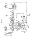
- Fig. 1 is a schematic view showing a first preferred embodiment of the drain recovery system in accordance with the invention;
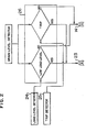
- Fig. 2 is a view showing a function of the change-over device in the system shown in Fig. 1;
- Fig. 3 is a diagram showing the relationship between the load level of the plant and the pressure in the portion of the condensate feedwater system at which the drains are injected thereinto;
- Fig. 4 is a diagram showing the relationship between the load level of the plant and the pressure drop at the outlet side of the drain pumps;
- Fig. 5 is a diagram showing the relationship between the load level of the plant and the required delivery head, i.e., the sum of the pressure shown in Fig. 3 and that shown in Fig. 4; and
- Fig. 6 is a schematic view showing a second preferred embodiment of the invention.
- Preferred embodiments of the invention will be described hereinunder with reference to the accompanying drawings.
- Referring first to Fig. 1, the steam generated in a nuclear reactor 1 is introduced into a high-
pressure turbine 2 and then into a low-pressure turbine 3 so as to drive the turbines. The steam which has been used in the low-pressure turbine is cascaded down in acondenser 4 to become a condensate, and the condensate is fed back as a feedwater to the nuclear reactor 1 through acondensate feedwater system 50. More specifically, the condensate in thecondenser 4 is sucked into and boosted by low-pressure condensate pumps 5 and is purified through acondensate filter 6 and a condensate desalination device 7 to a degree sufficient for the condensate to be able to be fed into the nuclear reactor. The condensate thus purified is sucked into and boosted by high-pressure condensate pumps 8 and is delivered to a low-pressure feedwater heater 9 in which the condensate is heated by the steam extracted from the low-pressure turbine 3. The heated condensate is sucked into and boosted byfeedwater pumps 10 and is delivered to a high-pressure feedwater heater 11 in which the condensate is further heated by the steam extracted from the high-pressure turbine 2 before supplied to the nuclear reactor 1 as the feedwater. - The high-pressure turbine extracted steam which has heated the condensate in the high-pressure feedwater heater 11 is condensed into a drain as a result of the heat exchange with the condensate. The drain is introduced into the low-pressure feedwater heater 9 by the pressure differential therebetween so as to heat the condensate in the low-pressure feedwater heater 9. The extracted steam which has heated the condensate in the low-pressure feedwater heater 9 is also condensed into a drain, which is sent to a
drain recovery system 51 together with the drain from the high-pressure feedwater heater which has heated the condensate in the low-pressure feedwater heater 9. - The
drain recovery system 51 has a drain pumping-uprecovery system 52 including adrain tank 12 for storing the feedwater heater drains, and a drainlevel control device 53 for maintaining the drain level in thedrain tank 12 at a predetermined position. - The
drain tank 12 of the drain pumping-uprecovery system 52 is connected to the low-pressure feedwater heater 9 so that the drain in the low-pressure feedwater heater 9 can be introduced into thedrain tank 12 by the pressure differential therebetween. Thedrain recovery system 51 also hasdrain pumps 13 which suck up the drains in thedrain tank 12 and delivers the same to adrain purifier 15 through acontrol valve 14. The purified drain from thedrain purifier 15 is injected, by the operation of thedrain pumps 13, into thecondensate feedwater system 50 at a predeterminedportion 16 thereof positioned on the inlet side of the high-pressure feedwater pump 8. Aminimum flow pipe 13a is connected between the outlet side of thedrain pump 13 and thedrain tank 12. When thecontrol valve 14 is closed, the drain discharged from thedrain pumps 13 is returned to thedrain tank 12 through theminimum flow pipe 13a, thereby securing the minimum flow rate necessary for the continuous operation of thedrain pumps 13. The drain level in thedrain tank 12 is detected by adrain level detector 17 and is maintained constant by the operation of thecontrol valve 14. With this arrangement, the flow rate of the drains injected into the condensate feedwater system at theportion 16 thereof is equalized to the flow rate of the drains introduced into thedrain tank 12, so that the required flow rate of the feedwater supplied to the nuclear reactor is ensured at theportion 16. The flow rate of the feedwater supplied to the nuclear reactor 1 is controlled by means of a speed controller (not shown) for the turbine which drives thefeedwater pumps 10, and also by a flow-rate control valve (not shown) provided on the outlet side of thefeedwater pumps 10 as the level of the water in the nuclear reactor 1 is detected by a water level detector (not shown). - In the embodiment shown in Fig. 1, the drain
level control device 53 has aconduit 22 through which adrain outlet pipe 18 is connected to thecondenser 4. Theconduit 22 is provided with asecond control valve 23. The drainlevel control device 53 further has a load level detector 24 which detects the level of the load of the plant, a trip detector 25 for detecting a trip of any one of thedrain pumps 13, and a change-overdevice 26 responsive to the output signals from the load level detector 24 and the trip detector 25 for selectively transferring the output signal from thedrain level detector 17 to either one of thefirst control valve 14 or thesecond control valve 23. - The
drain level detector 17 is adapted to generate a drain level signal when the drain level in thedrain tank 12 should exceed a predetermined position. The load level detector 24 detects the load level of the plant by detecting the flow rate of the feedwater supplied to the nuclear reactor 1 or by detecting the load imposed on an electric generator not shown for example. When the load level of the plant is low, the load level detector 24 produces a low load signal. The trip detector 25 detects a trip of any one of thedrain pumps 13 by sensing the delivery pressure of eachdrain pump 13, and produces a trip signal upon detection of the trip. - As will be seen from Fig. 2, the change-over
device 26 transfers the drain level signal from thedrain level detector 17 to thefirst control valve 14 when neither the low load signal nor the trip signal is outputted from the load level detector 24 and the trip detector 25, and it transfers the drain level signal to thesecond control valve 23 when at least one of the low level signal and the trip signal is outputted. - The operation of the
drain recovery system 51 will be explained hereinunder. - During normal operation of the plant, i.e., when the level of the load of the plant is not in the low-load range of 50% or lower and no trip of the
drain pumps 13 occurs, thedrain level detector 17 produces a drain level signal when the drain level in thedrain tank 12 should exceed the predetermined position. In this case, since neither the low load signal nor the trip signal is produced by the load level detector 24 and the trip detector 25, the change-overdevice 26 transfers the drain level signal to thefirst control valve 14, thereby opening the same. Consequently, the drains in thedrain tank 12 pumped up by thedrain pumps 13 are delivered to thedrain purifier 15 through thecontrol valve 14 and are injected into thecondensate feedwater system 50 at theportion 16 thereof for recovery therein. When the drain level in the drain tank has come down below the predetermined position, thedrain level detector 17 stops the delivery of the drain level signal so that thecontrol valve 14 is closed. In this case, thedrain pumps 13 continue to operate so that the drains delivered by the drain pumps are recirculated to thedrain tank 12 through theminimum flow pipe 13a. Thus, the drain level in thedrain tank 12 is maintained at the predetermined position, while the required flow rate of the feedwater supplied to the nuclear reactor 1 is secured. Thedrain pumps 13 may be designed such that they are automatically started and stopped in accordance with the operation of thecontrol valve 14. - When the load level of the plant is low, e.g., below 50%, as in the time of start-up of the plant, the load detector 24 produces the low load signal, so that the change-over
device 26 operates to transfer the drain level signal to thesecond control valve 23 in response to the low load signal from the load level detector 24. Therefore, when the drain level in thedrain tank 12 should exceed the predetermined position, thedrain level detector 17 produces the drain level signal which is transferred to thesecond control valve 23 through the change-overdevice 26, so that thesecond control valve 23 is opened. As a result, since a high vacuum has been established in thecondenser 4, the drains in thedrain tank 12 are sucked into thecondenser 4 through theconduit 22 by the pressure differential. At this time, thefirst control valve 14 is closed since the drain level signal is not transferred thereto, so that thedrain pump 13 operates to recirculate the drains through theminimum flow pipe 13a as explained below. - When the load level of the plant is low, the flow rate of the feedwater supplied to the nuclear reactor 1 is small, so that the low-pressure condensate pumps 5 can afford to feed the required flow rate of feedwater to the nuclear reactor 1.
- The drain pumps 13 are required to have a delivery head which equals to the sum of the pressure in the
portion 16 of thecondensate feedwater system 50 at which the drains are injected thereinto and the pressure drop at the delivery side of the drain pumps 13. According to the invention, it is possible to reduce the required delivery head of the drain pumps 13 by virtue of the operation of the drainlevel control device 53, as will be understood from the following description. - Fig. 3 shows the change in the pressure in the
portion 16 of the condensate feedwater system at which the drains are injected thereinto. It will be seen that the pressure at theportion 16 is comparatively high when the load level of the plant is low. This is attributable to the facts that at the low load level of the plant, the pressure drop along thecondensate feedwater system 50 is small due to the small flow rate of feedwater and also the delivery head of the condensate pump 5 is high due to the small flow rate of feedwater. - Fig. 4-shows the pressure drop at the delivery side of the drain pumps 13. It will be seen that the pressure drop is increased as the load level of the plant is increased. This is attributable to the fact that the amount of the drains from the feedwater heaters is increased with the increase in the load level of the plant. It will also be noted that the
drain purifier 15 is contaminated day by day, and as the contamination of thedrain purifier 15 becomes heavy, the pressure drop becomes serious even during low-load operation of the nuclear reactor in which the amount of drains is comparatively small. - Fig. 5 shows the sum of the pressure shown in Fig. 3 in the
portion 16 of thecondensate feedwater system 50 at which the drains are injected thereinto and the pressure drop shown in Fig. 4 experienced at the outlet side of the drain pumps 13. It will be seen that the delivery head required for injecting the drains at theportion 16 is increased as the load level becomes lower. It is assumed here that the drainlevel control device 53 is not provided so that the drain pumps 13 must deliver the drains to theportion 16 of thecondensate feedwater system 50 over the entire range of load levels of the plant. In such a case, a large difference in the required delivery head is observed since the required delivery head at the low load level of the plant is high while the required delivery head at the high load level of the plant is low. Thus, the drain pumps must satisfy a wide range of the required delivery head. This complicates the specification of the drain pumps and makes it difficult to design the drain pump system. - According to the invention, when the load level of plant is low, e.g., 50% or below, the drain
level control device 53 opens thesecond control valve 23 so as to maintain the drain level in thedrain tank 12 constant. Therefore, when the plant operates with a low load level such as 50% or below, it is not necessary to pump-up and deliver the drains to thecondensate feedwater system 50 by the drain pumps 13. It is, therefore, possible to reduce the delivery head required for the drain pumps 13 and, hence, to reduce the capacity of the drain pumps 13, which makes it possible to use smaller pumps as the drain pumps, while simplifying the design of the drain pumps system. In addition, the required flow rate of the feedwater supplied to the nuclear reactor 1 is maintained so that any risk of scram of the plant is avoided, as well as any risk of damage of the steam turbine which may otherwise occure as a result of rise of the drain level in thedrain tank 12. - When the drain pumps 13 malfunction and trip and the drain level in the
drain tank 12 should exceed the predetermined position, the trip detector 25 detects the trip and produces the trip signal while thedrain level detector 17 detects the drain level and produces the drain level signal. Thus, in response to the trip signal, the change-overdevice 26 transfers the drain level signal to thesecond control valve 23 thereby to open the same. Consequently, the drain in thedrain tank 12 is sucked into thecondenser 4 from thedrain tank 12 by the pressure differential therebetween, so that the drain level in thedrain tank 12 is maintained constant. - As a result, the -flow rate of the feedwater supplied to the nuclear reactor 1 is maintained so as to avoid any risk of scram of the nuclear reactor 1, as well as any risk of damage of the low-pressure turbine 3 which may otherwise occur as a result of rise of the drain level in the
drain tank 12. This in turn eliminates the necessity for the preparation of a spare drain pump, thus allowing a rationalization of the drain recovery system as a whole. - A second embodiment of the invention will be described hereinunder with reference to Fig. 6.
- In Fig. 6, the same reference numerals are used to denote the same or similar parts or members as those used in the embodiment shown in Fig. 1. The embodiment of the drain recovery system generally designated by a numeral 54 has a drain
level control device 55 including aconduit 32 connected between anoverflow pipe 31 disposed in thedrain tank 12 and thecondenser 4. Thisconduit 32 has no control valve but is provided with aloop seal 33 for maintaining a predetermined pressure differential between thedrain tank 12 and thecondenser 4. Theoverflow pipe 31 is positioned at a predetermined height within thedrain tank 12. - In this embodiment, the
drain level detector 17 of the drain pumping-uprecovery system 52 is directly connected to thecontrol valve 14. - During the normal operation in which the load level is not low, e.g., 50% or below and no trip of the
drain pump 13 occurs, thedrain level detector 17 produces a drain level signal when the drain level in thedrain tank 12 should exceed the predetermined position. In response to the drain level signal, thecontrol valve 14 opens so that the drain in thedrain tank 12 is pumped up and injected into thecondensate feedwater system 50 at theportion 16 thereof by the operation of the drain pumps 13. It is thus possible to maintain the required flow rate of the feedwater in thecondensate feedwater system 50, while maintaining a constant drain level in thedrain tank 12. During this operation, since a predetermined pressure differential is maintained between thedrain tank 12 and thecondenser 4 by virtue of theloop seal 33, the undesirable flush of hot drains in thedrain tank 12 which may otherwise occur by introduction of the vacuum from the condenser into the drain tank is prevented. This is turn avoids any reduction of temperature in thedrain tank 12 attributable to the transfer of vapor and heat from thedrain tank 12 into thecondenser 4. - During operation of the plant at a comparatively low load level, when the drain level in the drain tank should exceed the predetermined position, the drain level signal produced by the
drain level detector 17 also opens thecontrol valve 14. In this case, however, the drains cannot be injected into thecondensate feedwater system 50 at theportion 16 thereof, but is merely recirculated through theminimum flow pipe 13a. This is because the capacity of the drain pumps 13 is made so small as to just enough to provide the delivery head required when the load level of the plant is over 50%. Consequently, the level of the drains in thedrain tank 12 is further raised. However, when the drain level reaches an upper end of theoverflow pipe 31, the drains flow into thedrain conduit 32 and is sucked into thecondenser 4 by the pressure differential between thedrain tank 12 and thecondenser 4. It is thus possible to maintain a constant drain level in thedrain tank 12 by virtue of theoverflow pipe 31. Thus, the embodiment shown in Fig. 6 offers the same advantage as that produced by the first embodiment, owing to the fact that the drains introduced into thedrain tank 12 is recovered in thecondenser 4 through theoverflow pipe 31 and theconduit 32. - In addition, in the event of a rise of the drain level in the
drain tank 12 due to insufficient pump-up capacity caused by a trip of any one of the drain pumps 13, the drains are safely sucked into thecondenser 4 also through theoverflow pipe 31 and theconduit 32, so that various troubles and accidents which may otherwise be cause by the rise of the drain level are avoided as in the case of the embodiment shown in Fig. 1. - Besides the advantages brought about by the embodiment shown in Fig. 1, the embodiment shown in Fig. 6 offers another advantage in that it eliminates the control element which are required in the first embodiments for controlling the operations of the two control valves, thus contributing to a simplification of the control system.
- As apparent from the foregoing, in the present invention, the drain level in the drain tank can be maintained constant while the required flow rate of the feedwater supplied to the nuclear reactor 1 is secured, even if the drain pumps are not able to pump up and inject the drains to the condensate feedwater system during plant operation at a comparatively low load level, and therefore the size and capacity of the drain pumps can be reduced and the design of the drain pump system can be simplified.
- In addition, since the constant drain level in the
drain tank 12 and the required flow rate of the feedwater to the nuclear reactor are ensured even in the case of trip of the drain pumps, any risk of scram of the plant as well as damage of the turbine can be avoided and thus the necessity for the provision of a spare drain pump can be avoided advantageously.
Claims (11)
Applications Claiming Priority (2)
| Application Number | Priority Date | Filing Date | Title |
|---|---|---|---|
| JP60078369A JPS61237903A (en) | 1985-04-15 | 1985-04-15 | Controller for water level in drain tank for feedwater heater |
| JP78369/85 | 1985-04-15 |
Publications (2)
| Publication Number | Publication Date |
|---|---|
| EP0199179A1 EP0199179A1 (en) | 1986-10-29 |
| EP0199179B1 true EP0199179B1 (en) | 1990-03-07 |
Family
ID=13660092
Family Applications (1)
| Application Number | Title | Priority Date | Filing Date |
|---|---|---|---|
| EP86104801A Expired - Lifetime EP0199179B1 (en) | 1985-04-15 | 1986-04-08 | Drain recovery system for condensate feedwater system of nuclear power plant |
Country Status (4)
| Country | Link |
|---|---|
| US (1) | US4713209A (en) |
| EP (1) | EP0199179B1 (en) |
| JP (1) | JPS61237903A (en) |
| DE (1) | DE3669414D1 (en) |
Families Citing this family (5)
| Publication number | Priority date | Publication date | Assignee | Title |
|---|---|---|---|---|
| JPH02115602A (en) * | 1988-10-26 | 1990-04-27 | Toshiba Corp | Drain controller for feed water heater |
| JP5550020B2 (en) * | 2010-12-06 | 2014-07-16 | 株式会社日立製作所 | Water supply pump controller |
| US8946921B2 (en) | 2011-04-12 | 2015-02-03 | Plexaire, Llc | Pressure powered impeller system and related method of use |
| WO2014078428A1 (en) | 2012-11-13 | 2014-05-22 | Plexaire Llc | Condensate management system and methods |
| US10591177B2 (en) * | 2018-08-06 | 2020-03-17 | Emerson Electric Co. | System and method for thermostat detection of condensate switch tripping |
Family Cites Families (11)
| Publication number | Priority date | Publication date | Assignee | Title |
|---|---|---|---|---|
| GB926615A (en) * | 1959-05-01 | 1963-05-22 | Rolls Royce | Improvements in or relating to steam generating plant |
| GB889962A (en) * | 1959-05-04 | 1962-02-21 | Harold John Coles | Improvements in or relating to steam generators |
| CH379007A (en) * | 1960-08-29 | 1964-06-30 | Sulzer Ag | Nuclear reactor plant |
| JPS54152767A (en) * | 1978-05-24 | 1979-12-01 | Hitachi Ltd | Process accomodation control method |
| JPS55116010A (en) * | 1979-02-27 | 1980-09-06 | Hitachi Ltd | Method of controlling water level of steam condensation system |
| JPS5661589A (en) * | 1979-10-23 | 1981-05-27 | Hitachi Ltd | Water-level controller for side stream type condenser |
| DE3017531A1 (en) * | 1980-05-08 | 1981-11-12 | Kali-Chemie Ag, 3000 Hannover | METHOD FOR IMPROVING THE THERMAL STABILITY OF FLUORINE CHLORINE HYDROCARBONS |
| JPS588991A (en) * | 1981-07-08 | 1983-01-19 | Hitachi Ltd | Sidestream condensation system |
| DE3330012A1 (en) * | 1983-08-19 | 1985-03-07 | Kraftwerk Union AG, 4330 Mülheim | Boiling water reactor |
| JPS60201008A (en) * | 1984-03-26 | 1985-10-11 | Hitachi Ltd | Method and apparatus for controlling operation of plant |
| US4635589A (en) * | 1984-07-31 | 1987-01-13 | Westinghouse Electric Corp. | Model steam generator having an improved feedwater system |
-
1985
- 1985-04-15 JP JP60078369A patent/JPS61237903A/en active Pending
-
1986
- 1986-04-08 DE DE8686104801T patent/DE3669414D1/en not_active Expired - Lifetime
- 1986-04-08 EP EP86104801A patent/EP0199179B1/en not_active Expired - Lifetime
- 1986-04-15 US US06/852,315 patent/US4713209A/en not_active Expired - Fee Related
Also Published As
| Publication number | Publication date |
|---|---|
| JPS61237903A (en) | 1986-10-23 |
| EP0199179A1 (en) | 1986-10-29 |
| DE3669414D1 (en) | 1990-04-12 |
| US4713209A (en) | 1987-12-15 |
Similar Documents
| Publication | Publication Date | Title |
|---|---|---|
| US4651530A (en) | Method and apparatus for feed-water control in a steam generating plant | |
| US4713209A (en) | Drain recovery system for condensate feedwater system of nuclear power plant | |
| JP2685204B2 (en) | Water supply pump control method and apparatus | |
| JPS6141807A (en) | Feed water heater drain system | |
| US4434620A (en) | Condensation system for power plant | |
| JP2804615B2 (en) | Pump sealing device | |
| JP2736191B2 (en) | Reactor core cooling system | |
| JP3547458B2 (en) | High pressure drain pump shaft sealing equipment | |
| JPH0225160B2 (en) | ||
| JPS6391408A (en) | Feedwater heater drain system controller | |
| SU979835A1 (en) | Apparatus for controlling steam turbine plant heater | |
| JP2679980B2 (en) | Control device for water supply drain pump up system | |
| JPS62106207A (en) | Feedwater supply system in steam turbine plant | |
| JPS6338804A (en) | Condensate device | |
| JP2001349975A (en) | Reactor water injection system by steam turbine driven pump | |
| JPH01102202A (en) | Drain controller for feedwater heater | |
| JP2614279B2 (en) | Water supply and return control device | |
| JPH03115703A (en) | Cooling device of deaerator down take pipe | |
| JP3392563B2 (en) | Circulation heater for control rod drive system | |
| JPH0611104A (en) | Water heater Drain control device | |
| JPS62238904A (en) | Feedwater-heater drain controller | |
| JPS63197803A (en) | Nuclear-reactor water feeder | |
| JPH076607B2 (en) | Water heater Drain pump up system | |
| JPS62119302A (en) | Turbine plant with feedwater-heater drain injector | |
| SU1097811A1 (en) | Power unit dearatorless regeneration system |
Legal Events
| Date | Code | Title | Description |
|---|---|---|---|
| PUAI | Public reference made under article 153(3) epc to a published international application that has entered the european phase |
Free format text: ORIGINAL CODE: 0009012 |
|
| AK | Designated contracting states |
Kind code of ref document: A1 Designated state(s): DE FR |
|
| 17P | Request for examination filed |
Effective date: 19870326 |
|
| 17Q | First examination report despatched |
Effective date: 19880801 |
|
| GRAA | (expected) grant |
Free format text: ORIGINAL CODE: 0009210 |
|
| AK | Designated contracting states |
Kind code of ref document: B1 Designated state(s): DE FR |
|
| REF | Corresponds to: |
Ref document number: 3669414 Country of ref document: DE Date of ref document: 19900412 |
|
| ET | Fr: translation filed | ||
| PLBE | No opposition filed within time limit |
Free format text: ORIGINAL CODE: 0009261 |
|
| STAA | Information on the status of an ep patent application or granted ep patent |
Free format text: STATUS: NO OPPOSITION FILED WITHIN TIME LIMIT |
|
| 26N | No opposition filed | ||
| PGFP | Annual fee paid to national office [announced via postgrant information from national office to epo] |
Ref country code: FR Payment date: 19920228 Year of fee payment: 7 |
|
| PGFP | Annual fee paid to national office [announced via postgrant information from national office to epo] |
Ref country code: DE Payment date: 19920629 Year of fee payment: 7 |
|
| PG25 | Lapsed in a contracting state [announced via postgrant information from national office to epo] |
Ref country code: FR Effective date: 19931229 |
|
| PG25 | Lapsed in a contracting state [announced via postgrant information from national office to epo] |
Ref country code: DE Effective date: 19940101 |
|
| REG | Reference to a national code |
Ref country code: FR Ref legal event code: ST |