EP0199108A1 - Injection hose for a dilatation joint in concrete structures - Google Patents
Injection hose for a dilatation joint in concrete structures Download PDFInfo
- Publication number
- EP0199108A1 EP0199108A1 EP86103890A EP86103890A EP0199108A1 EP 0199108 A1 EP0199108 A1 EP 0199108A1 EP 86103890 A EP86103890 A EP 86103890A EP 86103890 A EP86103890 A EP 86103890A EP 0199108 A1 EP0199108 A1 EP 0199108A1
- Authority
- EP
- European Patent Office
- Prior art keywords
- injection
- strips
- openings
- injection hose
- base body
- Prior art date
- Legal status (The legal status is an assumption and is not a legal conclusion. Google has not performed a legal analysis and makes no representation as to the accuracy of the status listed.)
- Granted
Links
Images
Classifications
-
- E—FIXED CONSTRUCTIONS
- E04—BUILDING
- E04B—GENERAL BUILDING CONSTRUCTIONS; WALLS, e.g. PARTITIONS; ROOFS; FLOORS; CEILINGS; INSULATION OR OTHER PROTECTION OF BUILDINGS
- E04B1/00—Constructions in general; Structures which are not restricted either to walls, e.g. partitions, or floors or ceilings or roofs
- E04B1/62—Insulation or other protection; Elements or use of specified material therefor
- E04B1/66—Sealings
- E04B1/68—Sealings of joints, e.g. expansion joints
- E04B1/6816—Porous tubular seals for injecting sealing material
Definitions
- the invention relates to an injection hose for construction joints on concrete structures, with an essentially liquid-impermeable, body consisting of a flexible material such as rubber or plastic and enclosing a passage channel, which has radial openings along its length for the discharge of injection liquid along its length in the area of the radial openings has a depression extending over its length for receiving a strip covering the openings and made of material which is compressible under the pressure of the injection liquid, and having a tube of liquid-permeable material surrounding the base body and the strip.
- an injection hose which has an inner support body which has a liquid-permeable wall, a first liquid-permeable, network-like hose enveloping this support body and a second liquid-tight hose which surrounds this first hose.
- Injection hoses of this type are complex to manufacture and not always reliable in use because of the need for the special selection of the network-like hoses and tubular nonwovens, since it is necessary to match the network-like hoses and the tubular nonwoven to the concrete particles and the sealant used.
- the known injection hoses are also often difficult to install due to excessive rigidity and are easily damaged in rough construction site operation, which prevents the uniform distribution of the injection liquid over the entire length of the injection hose.
- an injection hose of the type mentioned is known from DE-GM 84 25 518.8, in which the radial opening for the outlet of the injection liquid is designed as a slot extending over the entire length of the base body and in which the edges of the strip are rounded and received in corresponding side recesses of the recess and the strip has a spring which engages in the slot.
- the invention has for its object to develop an injection hose of the type mentioned in such a way that it is easier to manufacture and handle and the injection liquid reaches the desired locations reliably and evenly.
- This object is achieved according to the invention in that a plurality of radial openings in the base body and the associated depressions and strips are distributed over the circumference of the base body in an angularly symmetrical manner (n-ray symmetrical; n 2: 2) with respect to the longitudinal axis.
- the solution according to the invention creates an injection hose which is simple to manufacture and handle and which ensures that the injection liquid can be fed to any desired location without problems.
- an embodiment of the invention which is particularly expedient in terms of production provides that the radial openings are designed as holes or slots arranged in longitudinal rows, the longitudinal rows being distributed at equal angular intervals over the circumference of the base body.
- the injection hose consists in a very advantageous manner only of a basic body and a corresponding number of strips provided in the depressions distributed around the circumference. A corresponding number of rows of holes and corresponding strips can be provided for different applications.
- the depressions and the associated strips have rectilinearly delimited side walls, which in particular (with respect to a certain depression) run at an acute angle to one another.
- This embodiment is also particularly useful for manufacturing reasons, because the base body and strips are easily extruded and the strips are easy to insert into their recesses.
- the width of the base of the depressions is only slightly larger than the diameter of the radial openings in the relevant direction.
- a diameter of the openings of approximately 3 mm is expediently provided, while the distance between the openings is advantageously approximately 2 cm and the diameter of the passage is approximately 6 mm.
- the base body consists of polyvinyl chloride and that the surrounding hose is made from a bobbin lace fabric.
- the strips covering the openings are advantageously made of foam rubber, foam rubber or neoprene, since this enables the required compressibility to be set easily.
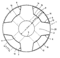
- the single figure illustrates in cross section an injection hose having the invention.
- the injection hose 1 consists of a base body 2, which has an essentially hollow cylindrical wall and thereby forms a continuous central cylindrical passage 3. Through this passage channel 3, the injection liquid is supplied to one or both ends of the injection hose 1 or, if appropriate, also with connections provided in between, in order to distribute it over the length of the construction joints to be sealed. Distributed over the circumference of the base body 2 at equal angular intervals, four depressions 5, 6, 7 and 8 are provided, which extend over the length of the base body 2. Radially extending openings 9, 10, 11 and 12 are provided for the flow connection of the passage channel 3 and the depressions 5, 6, 7, 8, which on the one hand open into the passage channel 3 and on the other hand into the depressions 5, 6, 7 and 8.
- the recesses 5, 6, 7 and 8 are of identical design for reasons of symmetry, so that only the recess 5 need be described in more detail here.
- the depression 5 has two side walls 13, 14, which are arranged at an angle converging inwards towards one another, so that there is an extension to the outer edge of the base body 2.
- the angle formed by the side walls 13, 14 is acute.
- the base 15 of the recess 5 is not significantly wider than the diameter of the associated openings 9.
- the bases 15 of the recesses 5, 6, 7 and 8 are rounded and lie on a common (imaginary) cylindrical surface.
- Strips 16, 17, 18 and 19 are arranged in the depressions 5, 6, 7 and 8, the shape of which is adapted to the shape of the depressions 5, 6, 7 and 8. They lie flush with the outer circumference of the projections of the base body 2 that have remained between the depressions 5, 6, 7 and 8.
- the distance between the openings 9, 10, 11 and 12 is expediently about 2 cm in the axial direction, the diameter of the passage 3 is expediently about 6 mm, while the diameter of the openings 9, 10, 11 and 12 is about 3 mm.
- the depth of the depressions 5, 6, 7 and 8 is also expediently 3 mm.
- the openings 9, 10, 11 and 12, viewed in the axial direction, can be offset with respect to the openings in the adjacent longitudinal row in order to even out the injection liquid outlet.
- Polyvinyl chloride is advantageous as the material for the base body 2, while the strips 16, 17, 18 and 19 consist of foam rubber, foam rubber or neoprene because of the desired compressibility.
- the base body 2 and the strips 16, 17, 18 and 19 arranged in the depressions 5, 6, 7 and 8, which essentially end with the outer circumference of the base body 2, are surrounded by a tube 20 made of a liquid-permeable material, which is made, for example, of a bobbin fabric can exist.
- a tube 20 made of a liquid-permeable material which is made, for example, of a bobbin fabric can exist.
- the penetration of concrete constituents from the outside into the passage 3 is reliably avoided, since when the pressure from the outside increases, the strips 16, 17, 18 and 19 only the openings 9, 10, 11 and 12 arranged in longitudinal rows seal even better. If, on the other hand, the injection liquid from the passage 3 presses outwards against the strips 16, 17, 18 and 19, these are pressed together due to their material properties and the joints between the depressions 5, 6, 7 and 8 and the strips 16, 17, 18 and 19 expanded so that the injection liquid can emerge from the injection hose 1 evenly over its length and circumference. The strips 16, 17, 18 and 19 are covered by the outer envelope Hose 20 is held in place so that the openings 9, 10, 11 and 12 are reliably closed again after the injection liquid has passed through.
- the injection hose 1 according to the invention is relatively insensitive to damage because of its thick walls.
- the enveloping hose 20 can also accept greater damage without losing its function as a holder for the strips 16, 17, 18 and 19 in the depressions 5, 6, 7 and 8.
- Elaborate support body u. The like. Are not necessary in the injection hose 1 according to the invention, so that overall there is an economical, easy, reliable and safe to use injection hose 1, which is also reliable in its function, in particular also in the uniform distribution of the injection liquid.
Abstract
Description
Die Erfindung betrifft einen Injektionsschlauch für Arbeitsfugen an Betonbauwerken, mit einem im wesentlichen flüssigkeitsundurchlässigen, aus flexiblem Material, wie Gummi oder Kunststoff, bestehenden einen Durchtrittskanal umschließenden Grundkörper, welcher entlang seiner Länge radiale Öffnungen für den Austritt von Injektionsflüssigkeit entlang seiner Länge im Bereich der radialen Öffnungen eine sich über seine Länge erstreckende Vertiefung für die Aufnahme eines die Öffnungen überdeckenden Streifens aus unter dem Druck der Injektionsflüssigkeit kompressiblen Material aufweist, und mit einem den Grundkörper und den Streifen umgebenden Schlauch aus flüssigkeitsdurchlässigem Material.The invention relates to an injection hose for construction joints on concrete structures, with an essentially liquid-impermeable, body consisting of a flexible material such as rubber or plastic and enclosing a passage channel, which has radial openings along its length for the discharge of injection liquid along its length in the area of the radial openings has a depression extending over its length for receiving a strip covering the openings and made of material which is compressible under the pressure of the injection liquid, and having a tube of liquid-permeable material surrounding the base body and the strip.
Aus der DE-PS 31 03 041 ist ein Injektionsschlauch bekannt, der einen inneren, eine flüssigkeitsdurchlässige Wandung aufweisenden Stützkörper, einen ersten, diesen Stützkörper umhüllenden flüssigkeitsdurchlässigen, netzwerkartigen Schlauch und einen zweiten, diesen ersten Schlauch umhüllenden flüssigkeitsdCrrchlässigen. netzwerkartigen Schlauch aufweist, wobei zwischen den beiden genannten netzwerkartigen Schläuchen ein schlauchförmiges Vlies vorgesehen ist, das für Betonpartikel von außen nach innen undurchlässig, für Dichtungsmittel von innen nach außen jedoch durchgängig ist. Derartige Injektionsschläuche sind wegen der Notwendigkeit der besonderen Auswahl der netzwerkartigen Schläuche und - schlauchförmigen Vliese aufwendig in der Herstellung und nicht immer zuverlässig in der Anwendung, da eine Abstimmung der netzwerkartigen Schläuche und des schlauchförmigen Vlieses auf die Betonpartikel und das verwendete Dichtungsmittel erforderlich ist. Die bekannten Injektionsschläuche sind außerdem häufig wegen zu hoher Steifigkeit schlecht zu verlegen und im rauhen Baustellenbetrieb leicht beschädigbar, was die gleichmäßige Verteilung der Injektionsflüssigkeit über die gesamte Länge des Injektionsschlauches verhindert.From DE-PS 31 03 041 an injection hose is known which has an inner support body which has a liquid-permeable wall, a first liquid-permeable, network-like hose enveloping this support body and a second liquid-tight hose which surrounds this first hose. has a network-like hose, a tubular fleece being provided between the two network-like hoses mentioned, which is impermeable from outside to inside for concrete particles, but is permeable from inside to outside for sealants. Injection hoses of this type are complex to manufacture and not always reliable in use because of the need for the special selection of the network-like hoses and tubular nonwovens, since it is necessary to match the network-like hoses and the tubular nonwoven to the concrete particles and the sealant used. The known injection hoses are also often difficult to install due to excessive rigidity and are easily damaged in rough construction site operation, which prevents the uniform distribution of the injection liquid over the entire length of the injection hose.
Zur Beseitigung dieser Nachteile ist aus dem DE-GM 84 25 518.8 ein Injektionsschlauch der eingangs genannten Art bekannt, bei dem die radiale Öffnung für den Austritt der Injecktionsflüssigkeit als sich über die gesamte Länge des Grundkörpers erstreckender Schlitz ausgebildet ist und bei dem die Ränder des Streifens abgerundet und in entsprechenden Seitenmulden der Vertiefung aufgenommen sind und der Streifen eine Feder aufweist, die in den Schlitz eingreift. Zwar sind mit dieser Vorschlag die Nachteile des aus der DE-PS 31 03 041 bekannten Injektionsschlauches behoben, er ist jedoch einer weiteren Verbesserung zugänglich.To eliminate these disadvantages, an injection hose of the type mentioned is known from DE-GM 84 25 518.8, in which the radial opening for the outlet of the injection liquid is designed as a slot extending over the entire length of the base body and in which the edges of the strip are rounded and received in corresponding side recesses of the recess and the strip has a spring which engages in the slot. Although this proposal eliminates the disadvantages of the injection hose known from DE-PS 31 03 041, it is accessible for further improvement.
Der Erfindung liegt die Aufgabe zugrunde, einen Injektionsschlauch der eingangs genannten Art so weiterzubilden, daß er einfacher herzustellen und zu handhaben sowie die Injektionsflüssigkeit zuverlässig gleichmäßig an die gewünschten Stellen gelangt.The invention has for its object to develop an injection hose of the type mentioned in such a way that it is easier to manufacture and handle and the injection liquid reaches the desired locations reliably and evenly.
Diese Aufgabe wird erfindungsgemäß-dadurch gelöst, daß mehrere radiale Öffnungen im Grundkörper und die zugeordneten Vertiefungen und Streifen über den Umfang des Grundkörpers winkelsymmetrisch (n-strahligsymmetrisch; n 2: 2) bezüglich der Längsachse verteilt sind.This object is achieved according to the invention in that a plurality of radial openings in the base body and the associated depressions and strips are distributed over the circumference of the base body in an angularly symmetrical manner (n-ray symmetrical; n 2: 2) with respect to the longitudinal axis.
Durch die erfindungsgemäße Lösung wird ein einfach herstellbarer und handhabbarer Injektionsschlauch geschaffen, bei dem gewährleistet ist, daß die Injektionsflüssigkeit jeder gewünschten Stelle problemlos zuführbar ist.The solution according to the invention creates an injection hose which is simple to manufacture and handle and which ensures that the injection liquid can be fed to any desired location without problems.
Eine bezüglich der Herstellung besonders zweckmäßige Ausführungsform der Erfindung sieht vor, daß die radialen Öffnungen als in Längsreihen angeordnete Löcher oder Schlitze ausgebildet sind, wobei die Längsreihen in gleichen Winkelabständen über den Umfang des Grundkörpers verteilt sind. Bei dieser Ausführungsform besteht der Injektionsschlauch in sehr vorteilhafter Weise lediglich aus einem Grundköper und einer entsprechenden Anzahl von in den um den Umfang verteilten Vertiefungen vorgesehen Streifen. Für verschiedene Anwendungsfälle kann dabei eine entsprechende Anzahl von Lochreihen und entsprechend Streifen vorgesehen sein. Insbesondere erscheint es aus Symmetriegründen zweckmäßig, vier Längsreihen von Öffnungen mit jeweils zugeordneten Vertiefungen und Streifen vorzusehen, die über den Umfang des Grundkörpers in gleichen Winkelabständen verteilt angeordnet sind.An embodiment of the invention which is particularly expedient in terms of production provides that the radial openings are designed as holes or slots arranged in longitudinal rows, the longitudinal rows being distributed at equal angular intervals over the circumference of the base body. In this embodiment, the injection hose consists in a very advantageous manner only of a basic body and a corresponding number of strips provided in the depressions distributed around the circumference. A corresponding number of rows of holes and corresponding strips can be provided for different applications. In particular, for reasons of symmetry, it appears expedient to provide four longitudinal rows of openings, each with associated depressions and strips, which are arranged at equal angular intervals distributed over the circumference of the base body.
Gemäß einer weiteren vorteilhaften Ausgestaltung der Erfindung ist vorgesehen, daß die Vertiefungen und die zugeordneten Streifen geradlinig begrenzte Seitenwände aufweisen, die insbesondere (bezogen auf eine bestimmte Vertiefung) in einem spitzen Winkel zueinander verlaufen. Auch diese Ausführungs form ist insbesondere aus herstellungstechnischen Gründen sehr zweckmäßig, weil Grundkörper und Streifen leicht extrudierbar und die Streifen einfach in ihre Vertiefungen einfügbar sind.According to a further advantageous embodiment of the invention, it is provided that the depressions and the associated strips have rectilinearly delimited side walls, which in particular (with respect to a certain depression) run at an acute angle to one another. This embodiment is also particularly useful for manufacturing reasons, because the base body and strips are easily extruded and the strips are easy to insert into their recesses.
Die Breite der Basis der Vertiefungen ist gemäß einem anderen Erfindungsmerkmal nur geringfügig größer als der Durchmesser der radialen Öffnungen in der betreffenden Richtung. Zweckmäßig ist ein Durchmesser der Öffnungen von etwa 3 mm vorgesehen, während der Abstand der Öffnung vorteilhafterweise etwa 2 cm und der Durchmesser des Durchtrittskanals etwa 6 mm betragen. Weiterbildungen der Erfindung sehen vor, daß der Grundkörper aus Polyvinylchlorid besteht, und daß der umgebende Schlauch aus einem Klöppelgewebe gefertigt ist. Die die Öffnungen abdeckenden Streifen bestehen mit Vorteil aus Schaumgummi, Moosgummi oder Neopren, da hierdurch die erforderliche Kompressibilität einfach eingestellt werden kann.According to another feature of the invention, the width of the base of the depressions is only slightly larger than the diameter of the radial openings in the relevant direction. A diameter of the openings of approximately 3 mm is expediently provided, while the distance between the openings is advantageously approximately 2 cm and the diameter of the passage is approximately 6 mm. Further developments of the invention provide that the base body consists of polyvinyl chloride and that the surrounding hose is made from a bobbin lace fabric. The strips covering the openings are advantageously made of foam rubber, foam rubber or neoprene, since this enables the required compressibility to be set easily.
Weitere Ziele, Merkmale, Vorteile und Anwendungsmöglichkeiten der vorliegenden Erfindung ergeben sich aus der nachfolgenden Beschreibung eines Ausführungsbeispiels anhand der beiliegenden Zeichnung. Dabei bilden alle beschriebenen und/oder bildlich dargestellten Merkmale für sich oder in beliebiger sinnvoller Kombination den Gegenstand der vorliegenden Erfindung, auch unabhängig von ihrer Zusammenfassung in den Ansprüchen oder deren Rückbeziehung.Further objectives, features, advantages and possible uses of the present invention result from the following description of an exemplary embodiment with reference to the accompanying drawing. All of the described and / or illustrated features, alone or in any meaningful combination, form the subject matter of the present invention, regardless of how they are summarized in the claims or their relationship.
Die einzige Figur veranschaulicht im Querschnitt einen die Erfindung aufweisenden Injektionsschlauch.The single figure illustrates in cross section an injection hose having the invention.
Der Injektionsschlauch 1 besteht aus einem Grundkörper 2, der eine im wesentlichen hohlzylindrische Wandung hat und dadurch einen durchgehenden zentralen zylindrischen Durchtrittskanal 3 bildet. Durch diesen Durchtrittskanal 3 wird an einem oder beiden Enden des Injektionsschlauches 1 bzw. gegebenenfalls auch bei dazwischen vorgesehen Anschlüssen die Injektionsflüssigkeit zugeführt, um sie über die Länge der abzudichtenden Arbeitsfugen zu verteilen. Über den Umfang des Grundkörpers 2 in gleichen Winkelabständen verteilt sind vier Vertiefungen 5, 6, 7 und 8 vorgesehen, die sich über die Länge des Grundkörpers 2 erstrecken. Zur Strömungsverbindung des Durchtrittskanales 3 und der Vertiefungen 5, 6. 7, 8 sind radial verlaufende Öffnungen 9, 10, 11 und 12 vorgesehen, die einerseits in den Durchtrittskanal 3 und andererseits in die Vertiefungen 5. 6, 7 und 8 münden. Die Vertiefungen 5, 6, 7 und 8 sind aus Symmetriegründen gleich ausgebildet, so daß hier nur die Vertiefung 5 näher beschrieben zu werden braucht. Die Vertiefung 5 weist zwei Seitenwände 13, 14 auf, die im Winkel schräg nach innen zusammenlaufend zueinander angeordnet sind, so daß zum Außenrand des Grundkörpers 2 eine Erweiterung vorliegt. Der von den Seitenwänden 13, 14 gebildete Winkel ist spitz. Die Basis 15 der Vertiefung 5 ist nicht wesentlich breiter als der Durchmesser der zugeordneten Öffnungen 9. Die Basen 15 der Vertiefungen 5, 6, 7 und 8 sind abgerundet und liegen auf einer gemeinsamen (gedachten) Zylinderfläche. In den Vertiefungen 5, 6, 7 und 8 sind Streifen 16, 17, 18 und 19 angeordnet, deren Form der Form der Vertiefungen 5, 6, 7 und 8 angepaßt ist. Sie liegen bündig mit dem Außenumfang der zwischen den Vertiefungen 5, 6, 7 und 8 stehengebliebenen Vorsprünge des Grundkörpers 2.The
Der Abstand der Öffnungen 9, 10, 11 und 12 beträgt in AXIalrichtung zweckmäßig etwa 2 cm, der Durchmesser des Durchtrittskanals 3 beträgt zweckmäßig etwa 6 mm, während der Durchmesser der Öffnungen 9, 10, 11 und 12 bei etwa 3 mm liegt. Auch die Tiefe der Vertiefungen 5, 6, 7 und 8 beträgt zweckmäßig 3 mm. Die Öffnungen 9, 10, 11 und 12 können in Axialrichtung gesehen gegenüber den Öffnungen der Nachbarlängsreihe versetzt sein, um den Injektionsflüssigkeitsaustritt zu vergleichmäßigen. Als Material für den Grundkörper 2 ist Polyvinylchlorid vorteilhaft, während die Streifen 16, 17, 18 und 19 wegen der gewünschten Kompressibilität aus Schaumgummi, Moosgummi oder Neopren bestehen. Der Grundkörper 2 und die in den Vertiefungen 5, 6, 7 und 8 angeordneten Streifen 16, 17, 18 und 19, die mit dem Außenumfang des Grundkörpers 2 im wesentlichen abschließen, sind von einem Schlauch 20 aus einem flüssigkeitsdurchlässigen Material umgeben, der beispielsweise aus einem Klöppelgewebe besteht kann. Hierdurch werden die Streifen 16, 17, 18 und 19 in ihren Vertiefungen 5, 6, 7 und 8 sicher gehalten, auch wenn der Druck der Injektionsflüssigkeit von innen ansteht.The distance between the
Bei dem erfindungsgemäßen Injektionsschlauch 1 ist das Eindringen von Beton-Bestandteilen von außen in den Durchtrittskanal 3 zuverlässig vermieden, da bei Erhöhung des Druckes von außen die Streifen 16, 17, 18 und 19 die in Längsreihen angeordneten Öffnungen 9, 10, 11 und 12 nur noch besser verschließen. Drückt dagegen die Injektionsflüssigkeit aus dem Durchtrittskanal 3 nach außen gegen die Streifen 16, 17, 18 und 19, so werden diese aufgrund ihrer Materialbeschaffenheit zusammengepreßt und die Fugen zwischen den Vertiefungen 5, 6. 7 und 8 und den Streifen 16, 17, 18 und 19 so erweitert, daß die Injektionsflüssigkeit aus dem Injektionsschlauch 1 gleichmäßig über seine Länge und seinen Umfang austreten kann. Die Streifen 16, 17. 18 und 19 werden dabei durch den äußeren umhüllenden Schlauch 20 an Ort und Stelle gehalten, so daß nach dem Durchtritt der Injektionsflüssigkeit die Öffnungen 9, 10. 11 und 12 wieder zuverlässig verschlossen werden.In the
Der erfindungsgemäße Injektionsschlauch 1 ist wegen seiner Dickwandigkeit relativ unempfindlich gegen Beschädigungen. Auch kann der umhüllende Schlauch 20 größere Beschädigungen in Kauf nehmen, ohne seine Funktion als Halterung für die Streifen 16, 17, 18 und 19 in den Vertiefungen 5, 6, 7 und 8 zu verlieren. Aufwendige Stützkörper u. dgl. sind bei dem erfindungsgemäßen Injektionsschlauch 1 nicht erforderlich, so daß sich insgesamt eine wirtschaftlich herzustellender, leicht, zuverlässig und sicher zu handhabender Injektionsschlauch 1 ergibt, der auch zuverlässig in seiner Funktion, insbesondere auch in der gleichmäßigen Verteilung der Injektionsflüssigkeit ist.The
- 1 Injektionsschlauch1 injection hose
- 2 Grundkörper2 basic bodies
- 3 Durchtrittskanal3 passage channel
- 5 Vertiefung5 deepening
- 6 Vertiefung6 deepening
- 7 Vertiefung7 deepening
- 8 Vertiefung8 deepening
- 9 Öffnung9 opening
- 10 Öffnung10 opening
- 11 Öffnung11 opening
- 12 Öffnung12 opening
- 13 Seitenwand13 side wall
- 14 Seitenwand14 side wall
- 15 Basis15 base
- 16 Streifen16 strips
- 17 Streifen17 strips
- 18 Streifen18 strips
- 19 Streifen19 strips
- 20 Schlauch20 hose
Claims (14)
Priority Applications (1)
| Application Number | Priority Date | Filing Date | Title |
|---|---|---|---|
| AT86103890T ATE39720T1 (en) | 1985-04-04 | 1986-03-21 | INJECTION HOSE FOR CONSTRUCTION JOINTS ON CONCRETE STRUCTURES. |
Applications Claiming Priority (2)
| Application Number | Priority Date | Filing Date | Title |
|---|---|---|---|
| DE3512470A DE3512470C2 (en) | 1985-04-04 | 1985-04-04 | Injection hose for construction joints on concrete structures |
| DE3512470 | 1985-04-04 |
Publications (2)
| Publication Number | Publication Date |
|---|---|
| EP0199108A1 true EP0199108A1 (en) | 1986-10-29 |
| EP0199108B1 EP0199108B1 (en) | 1989-01-04 |
Family
ID=6267386
Family Applications (1)
| Application Number | Title | Priority Date | Filing Date |
|---|---|---|---|
| EP86103890A Expired EP0199108B1 (en) | 1985-04-04 | 1986-03-21 | Injection hose for a dilatation joint in concrete structures |
Country Status (6)
| Country | Link |
|---|---|
| US (1) | US4722479A (en) |
| EP (1) | EP0199108B1 (en) |
| AT (1) | ATE39720T1 (en) |
| DE (2) | DE3512470C2 (en) |
| DK (1) | DK162454C (en) |
| NO (1) | NO166810C (en) |
Cited By (5)
| Publication number | Priority date | Publication date | Assignee | Title |
|---|---|---|---|---|
| WO1992016696A1 (en) * | 1991-03-19 | 1992-10-01 | Bjarne Sem | Injection tube for chemical injection in concrete |
| DE4340845A1 (en) * | 1993-11-26 | 1995-06-01 | Ibs Injektionstechnologie Gmbh | Plastic seal for use in the building industry |
| EP0692584A1 (en) | 1994-07-15 | 1996-01-17 | Daniel Strasser | Waterstop seal for concrete works |
| WO1999013174A1 (en) | 1997-09-11 | 1999-03-18 | Betomax Kunststoff- Und Metallwarenfabrik Gmbh & Co. Kg | Compression tubing for producing water-impermeable or only slightly water-permeable, gastight and/or friction-locked building joints |
| EP3392422A1 (en) | 2017-04-18 | 2018-10-24 | Roland Wolf | Device for the subsequent stabilisation of water-permeable gap chamber breaks in bridges, tunnels and buildings |
Families Citing this family (17)
| Publication number | Priority date | Publication date | Assignee | Title |
|---|---|---|---|---|
| JPS63163860A (en) * | 1986-12-26 | 1988-07-07 | Toshiba Corp | Electrophotographic sensitive body |
| DE8915525U1 (en) * | 1989-09-08 | 1990-09-27 | Pflieger, Lieselotte, 7405 Dettenhausen, De | |
| DE4123067A1 (en) * | 1991-07-12 | 1993-01-14 | Betonbau Zubehoer Handel | METHOD FOR SEALING JOINTS ON CONSTRUCTIONS |
| DE4124628A1 (en) * | 1991-07-25 | 1993-01-28 | Betonbau Zubehoer Handel | INJECTION HOSE FOR JOINTS ON CONSTRUCTIONS |
| DE4215731A1 (en) * | 1992-05-13 | 1993-11-18 | Rene P Schmid | Process for erecting concrete walls using formwork, and device and means for carrying out this process |
| DE4332589C2 (en) * | 1993-09-24 | 1996-01-04 | Bbz Inj Und Abdichtungstechnik | Injection hose for construction joints on concrete structures |
| DE4419376C1 (en) * | 1994-05-27 | 1995-08-31 | Michael Dipl Chem Schoeniger | Injection tube for sealing joints in concrete |
| AT404745B (en) * | 1995-07-27 | 1999-02-25 | Strasser Daniel | GASKET FOR WORK JOINTS IN AND ON CONCRETE CONSTRUCTIONS |
| DE19625209A1 (en) * | 1996-06-25 | 1998-01-02 | Sika Ag | Injection hose and process for its manufacture |
| DE19726403C1 (en) * | 1997-06-21 | 1999-02-04 | Rasbach Klaus | Injection tube for cement constructions |
| US6286271B1 (en) | 1999-05-26 | 2001-09-11 | Carl Cheung Tung Kong | Load-bearing structural member |
| JP2002089757A (en) * | 2000-09-18 | 2002-03-27 | Hara Kogyo Kk | Injection hose and placing joint method of concrete |
| EP1608824B1 (en) * | 2003-03-05 | 2007-06-13 | Herman De Neef | Means and method for sealing concrete construction joints and method for manufacturing such sealing means |
| DE102008010660B3 (en) * | 2008-02-22 | 2009-09-24 | Repower Systems Ag | Construction of a wind turbine |
| CN102296637A (en) * | 2011-06-13 | 2011-12-28 | 华南理工大学 | Seepage-proofing joint device of diaphragm wall |
| US20140183278A1 (en) * | 2013-01-03 | 2014-07-03 | Clive Sofus Michelsen | Perforated fluid dispensing hose or tube for the purpose of applying liquids and/or gases to railroad tracks including railroad switches, railroad crossings, bridge overheads and tunnel walls |
| DE102017108167A1 (en) | 2017-04-18 | 2018-10-18 | Roland Wolf | Device for the subsequent stabilization of water-permeable joint chamber cracks in bridges, tunnels and buildings |
Citations (3)
| Publication number | Priority date | Publication date | Assignee | Title |
|---|---|---|---|---|
| DE3103041A1 (en) * | 1980-03-05 | 1981-11-26 | Peter 6405 Immensee Kaufmann | HOSE-TYPE SEALING DEVICE FOR CONCRETE JOINTS AND METHOD FOR PRODUCING A CONCRETE JOINT SEAL |
| DE8425518U1 (en) * | 1984-08-29 | Koob, Kunibert, Ing.(grad.), 4234 Alpen | Injection tube | |
| EP0125696A2 (en) * | 1983-05-17 | 1984-11-21 | Eva-Maria Rasbach | Porous multiple-layer tube |
Family Cites Families (7)
| Publication number | Priority date | Publication date | Assignee | Title |
|---|---|---|---|---|
| DE8314491U1 (en) * | 1983-09-15 | Rasbach, Heinz, Dipl.-Ing., 6204 Taunusstein | Multi-layer, porous hose | |
| US2798768A (en) * | 1955-12-23 | 1957-07-09 | Babin Benton Paul | Soil moistening apparatus |
| US3157536A (en) * | 1962-07-20 | 1964-11-17 | Eastman Kodak Co | Apparatus for applying plasticizer to filter tow |
| CY893A (en) * | 1972-06-02 | 1977-10-07 | Rosenberg P | Floid flow control device for use as a water trickler nozzle |
| SU471093A1 (en) * | 1973-05-29 | 1975-05-25 | Украинский Научно-Исследовательский Институт Гидротехники И Мелиорации | Subsoil irrigation humidifier |
| US3946762A (en) * | 1974-07-29 | 1976-03-30 | Green Edwin J | Underground irrigation system |
| JPS5714036Y2 (en) * | 1976-06-01 | 1982-03-23 |
-
1985
- 1985-04-04 DE DE3512470A patent/DE3512470C2/en not_active Expired - Fee Related
-
1986
- 1986-03-21 DE DE8686103890T patent/DE3661643D1/en not_active Expired
- 1986-03-21 AT AT86103890T patent/ATE39720T1/en not_active IP Right Cessation
- 1986-03-21 EP EP86103890A patent/EP0199108B1/en not_active Expired
- 1986-03-26 US US06/844,012 patent/US4722479A/en not_active Expired - Lifetime
- 1986-04-02 NO NO861284A patent/NO166810C/en not_active IP Right Cessation
- 1986-04-04 DK DK155386A patent/DK162454C/en not_active IP Right Cessation
Patent Citations (3)
| Publication number | Priority date | Publication date | Assignee | Title |
|---|---|---|---|---|
| DE8425518U1 (en) * | 1984-08-29 | Koob, Kunibert, Ing.(grad.), 4234 Alpen | Injection tube | |
| DE3103041A1 (en) * | 1980-03-05 | 1981-11-26 | Peter 6405 Immensee Kaufmann | HOSE-TYPE SEALING DEVICE FOR CONCRETE JOINTS AND METHOD FOR PRODUCING A CONCRETE JOINT SEAL |
| EP0125696A2 (en) * | 1983-05-17 | 1984-11-21 | Eva-Maria Rasbach | Porous multiple-layer tube |
Cited By (7)
| Publication number | Priority date | Publication date | Assignee | Title |
|---|---|---|---|---|
| WO1992016696A1 (en) * | 1991-03-19 | 1992-10-01 | Bjarne Sem | Injection tube for chemical injection in concrete |
| DE4340845A1 (en) * | 1993-11-26 | 1995-06-01 | Ibs Injektionstechnologie Gmbh | Plastic seal for use in the building industry |
| DE4340845C2 (en) * | 1993-11-26 | 2002-12-19 | Ibs Injektionstechnologie Gmbh | Injection profile for sealing joints on buildings |
| EP0692584A1 (en) | 1994-07-15 | 1996-01-17 | Daniel Strasser | Waterstop seal for concrete works |
| WO1999013174A1 (en) | 1997-09-11 | 1999-03-18 | Betomax Kunststoff- Und Metallwarenfabrik Gmbh & Co. Kg | Compression tubing for producing water-impermeable or only slightly water-permeable, gastight and/or friction-locked building joints |
| EP3392422A1 (en) | 2017-04-18 | 2018-10-24 | Roland Wolf | Device for the subsequent stabilisation of water-permeable gap chamber breaks in bridges, tunnels and buildings |
| WO2018192935A1 (en) | 2017-04-18 | 2018-10-25 | Roland Wolf | Device for subsequent stabilisation of water-permeable joint cavity cracks in bridges, tunnels and buildings |
Also Published As
| Publication number | Publication date |
|---|---|
| DK155386A (en) | 1986-10-05 |
| DK162454C (en) | 1992-03-23 |
| NO166810B (en) | 1991-05-27 |
| EP0199108B1 (en) | 1989-01-04 |
| NO861284L (en) | 1986-10-06 |
| DE3512470C2 (en) | 1996-01-04 |
| ATE39720T1 (en) | 1989-01-15 |
| US4722479A (en) | 1988-02-02 |
| DK162454B (en) | 1991-10-28 |
| NO166810C (en) | 1991-09-04 |
| DE3512470A1 (en) | 1986-10-09 |
| DK155386D0 (en) | 1986-04-04 |
| DE3661643D1 (en) | 1989-02-09 |
Similar Documents
| Publication | Publication Date | Title |
|---|---|---|
| EP0199108B1 (en) | Injection hose for a dilatation joint in concrete structures | |
| DE19722842C2 (en) | Detachable quick coupling | |
| DE2908952B2 (en) | Drainage device | |
| EP0013911B1 (en) | Plastic dowel | |
| EP0720681A1 (en) | Injection hose for concrete construction joints | |
| DE3906967C1 (en) | ||
| DE2260940A1 (en) | PAD APPLICATOR | |
| DE8425518U1 (en) | Injection tube | |
| DE2829938A1 (en) | CONNECTOR | |
| DE3619399C2 (en) | Tether | |
| DE2431834A1 (en) | Wall mounting multi-layer cable support bracket - has sprung flanged ends to assist in retaining cables | |
| DE2704663C2 (en) | Pipe connection made of elastic material for toilet bowls | |
| DE1489469B2 (en) | LAMP SOCKET FOR DETACHABLE FASTENING IN A RECESSED OPENING | |
| DE2628675A1 (en) | Communication cable coupling inlet seal - has disc with concentric rings linked by radial arms to outer ring to allow adjustment for different cable sizes | |
| EP0039467A2 (en) | Spacer | |
| DE19907204A1 (en) | Sealing element | |
| DE4226157C1 (en) | ||
| DE3301229C2 (en) | ||
| EP0229087A1 (en) | Flexible hose | |
| EP3079214B1 (en) | Closure stopper for a cable shaft or a cable laying tube | |
| EP0043423B1 (en) | Supporting spacer for pipes inside other pipes, especially for holding tubes of tube mail systems within protection tubes | |
| DE8501549U1 (en) | Paint roller | |
| DE2314176C2 (en) | Open, elastic clamping ring for use especially in sewage technology | |
| EP1012417A1 (en) | Compression tubing for producing water-impermeable or only slightly water-permeable, gastight and/or friction-locked building joints | |
| DE2141349A1 (en) | DEVICE FOR CLEANING PIPELINES |
Legal Events
| Date | Code | Title | Description |
|---|---|---|---|
| PUAI | Public reference made under article 153(3) epc to a published international application that has entered the european phase |
Free format text: ORIGINAL CODE: 0009012 |
|
| AK | Designated contracting states |
Kind code of ref document: A1 Designated state(s): AT BE CH DE FR GB IT LI LU NL SE |
|
| ITCL | It: translation for ep claims filed |
Representative=s name: BUGNION S.P.A. |
|
| 17P | Request for examination filed |
Effective date: 19870410 |
|
| TCNL | Nl: translation of patent claims filed | ||
| EL | Fr: translation of claims filed | ||
| 17Q | First examination report despatched |
Effective date: 19880121 |
|
| GRAA | (expected) grant |
Free format text: ORIGINAL CODE: 0009210 |
|
| AK | Designated contracting states |
Kind code of ref document: B1 Designated state(s): AT BE CH DE FR GB IT LI LU NL SE |
|
| REF | Corresponds to: |
Ref document number: 39720 Country of ref document: AT Date of ref document: 19890115 Kind code of ref document: T |
|
| REF | Corresponds to: |
Ref document number: 3661643 Country of ref document: DE Date of ref document: 19890209 |
|
| ITF | It: translation for a ep patent filed |
Owner name: BUGNION S.P.A. |
|
| GBT | Gb: translation of ep patent filed (gb section 77(6)(a)/1977) | ||
| ET | Fr: translation filed | ||
| REG | Reference to a national code |
Ref country code: CH Ref legal event code: PUE Owner name: BBZ AG |
|
| PLBE | No opposition filed within time limit |
Free format text: ORIGINAL CODE: 0009261 |
|
| STAA | Information on the status of an ep patent application or granted ep patent |
Free format text: STATUS: NO OPPOSITION FILED WITHIN TIME LIMIT |
|
| 26N | No opposition filed | ||
| ITTA | It: last paid annual fee | ||
| EPTA | Lu: last paid annual fee | ||
| EAL | Se: european patent in force in sweden |
Ref document number: 86103890.9 |
|
| REG | Reference to a national code |
Ref country code: FR Ref legal event code: TP |
|
| NLS | Nl: assignments of ep-patents |
Owner name: TRICOSAL GMBH |
|
| REG | Reference to a national code |
Ref country code: CH Ref legal event code: PFA Free format text: BBZ AG,BAHNHOFPLATZ 11,9100 HERISAU (CH) TRANSFER- BBZ AG,ROTFARBSTRASSE 8,9213 HAUPTWIL (CH) Ref country code: CH Ref legal event code: NV Representative=s name: ISLER & PEDRAZZINI AG |
|
| REG | Reference to a national code |
Ref country code: GB Ref legal event code: 732E |
|
| PGFP | Annual fee paid to national office [announced via postgrant information from national office to epo] |
Ref country code: GB Payment date: 20000301 Year of fee payment: 15 |
|
| PGFP | Annual fee paid to national office [announced via postgrant information from national office to epo] |
Ref country code: BE Payment date: 20000324 Year of fee payment: 15 Ref country code: AT Payment date: 20000324 Year of fee payment: 15 |
|
| PGFP | Annual fee paid to national office [announced via postgrant information from national office to epo] |
Ref country code: LU Payment date: 20000404 Year of fee payment: 15 |
|
| PGFP | Annual fee paid to national office [announced via postgrant information from national office to epo] |
Ref country code: FR Payment date: 20010319 Year of fee payment: 16 |
|
| PG25 | Lapsed in a contracting state [announced via postgrant information from national office to epo] |
Ref country code: LU Free format text: LAPSE BECAUSE OF NON-PAYMENT OF DUE FEES Effective date: 20010321 Ref country code: GB Free format text: LAPSE BECAUSE OF NON-PAYMENT OF DUE FEES Effective date: 20010321 Ref country code: AT Free format text: LAPSE BECAUSE OF NON-PAYMENT OF DUE FEES Effective date: 20010321 |
|
| PGFP | Annual fee paid to national office [announced via postgrant information from national office to epo] |
Ref country code: SE Payment date: 20010323 Year of fee payment: 16 |
|
| PGFP | Annual fee paid to national office [announced via postgrant information from national office to epo] |
Ref country code: NL Payment date: 20010326 Year of fee payment: 16 |
|
| PG25 | Lapsed in a contracting state [announced via postgrant information from national office to epo] |
Ref country code: BE Free format text: LAPSE BECAUSE OF NON-PAYMENT OF DUE FEES Effective date: 20010331 |
|
| REG | Reference to a national code |
Ref country code: CH Ref legal event code: PFA Free format text: BBZ AG TRANSFER- TRICOSAL BBZ AG |
|
| BERE | Be: lapsed |
Owner name: TRICOSAL G.M.B.H. Effective date: 20010331 |
|
| GBPC | Gb: european patent ceased through non-payment of renewal fee |
Effective date: 20010321 |
|
| PG25 | Lapsed in a contracting state [announced via postgrant information from national office to epo] |
Ref country code: SE Free format text: LAPSE BECAUSE OF NON-PAYMENT OF DUE FEES Effective date: 20020322 |
|
| PG25 | Lapsed in a contracting state [announced via postgrant information from national office to epo] |
Ref country code: NL Free format text: LAPSE BECAUSE OF NON-PAYMENT OF DUE FEES Effective date: 20021001 |
|
| EUG | Se: european patent has lapsed |
Ref document number: 86103890.9 |
|
| PG25 | Lapsed in a contracting state [announced via postgrant information from national office to epo] |
Ref country code: FR Free format text: LAPSE BECAUSE OF NON-PAYMENT OF DUE FEES Effective date: 20021129 |
|
| NLV4 | Nl: lapsed or anulled due to non-payment of the annual fee |
Effective date: 20021001 |
|
| REG | Reference to a national code |
Ref country code: FR Ref legal event code: ST |
|
| PGFP | Annual fee paid to national office [announced via postgrant information from national office to epo] |
Ref country code: CH Payment date: 20040323 Year of fee payment: 19 |
|
| PGFP | Annual fee paid to national office [announced via postgrant information from national office to epo] |
Ref country code: DE Payment date: 20040527 Year of fee payment: 19 |
|
| PG25 | Lapsed in a contracting state [announced via postgrant information from national office to epo] |
Ref country code: IT Free format text: LAPSE BECAUSE OF NON-PAYMENT OF DUE FEES;WARNING: LAPSES OF ITALIAN PATENTS WITH EFFECTIVE DATE BEFORE 2007 MAY HAVE OCCURRED AT ANY TIME BEFORE 2007. THE CORRECT EFFECTIVE DATE MAY BE DIFFERENT FROM THE ONE RECORDED. Effective date: 20050321 |
|
| PG25 | Lapsed in a contracting state [announced via postgrant information from national office to epo] |
Ref country code: LI Free format text: LAPSE BECAUSE OF NON-PAYMENT OF DUE FEES Effective date: 20050331 Ref country code: CH Free format text: LAPSE BECAUSE OF NON-PAYMENT OF DUE FEES Effective date: 20050331 |
|
| PG25 | Lapsed in a contracting state [announced via postgrant information from national office to epo] |
Ref country code: DE Free format text: LAPSE BECAUSE OF NON-PAYMENT OF DUE FEES Effective date: 20051001 |
|
| REG | Reference to a national code |
Ref country code: CH Ref legal event code: PL |