EP0197930B1 - Anordnung zur wegeauswahl in einem nachrichtennetz - Google Patents
Anordnung zur wegeauswahl in einem nachrichtennetz Download PDFInfo
- Publication number
- EP0197930B1 EP0197930B1 EP84904186A EP84904186A EP0197930B1 EP 0197930 B1 EP0197930 B1 EP 0197930B1 EP 84904186 A EP84904186 A EP 84904186A EP 84904186 A EP84904186 A EP 84904186A EP 0197930 B1 EP0197930 B1 EP 0197930B1
- Authority
- EP
- European Patent Office
- Prior art keywords
- terminal
- path selection
- selection equipment
- network
- computer
- Prior art date
- Legal status (The legal status is an assumption and is not a legal conclusion. Google has not performed a legal analysis and makes no representation as to the accuracy of the status listed.)
- Expired
Links
Images

Classifications
-
- G—PHYSICS
- G06—COMPUTING OR CALCULATING; COUNTING
- G06F—ELECTRIC DIGITAL DATA PROCESSING
- G06F15/00—Digital computers in general; Data processing equipment in general
- G06F15/16—Combinations of two or more digital computers each having at least an arithmetic unit, a program unit and a register, e.g. for a simultaneous processing of several programs
- G06F15/163—Interprocessor communication
- G06F15/173—Interprocessor communication using an interconnection network, e.g. matrix, shuffle, pyramid, star, snowflake
- G06F15/17356—Indirect interconnection networks
-
- G—PHYSICS
- G06—COMPUTING OR CALCULATING; COUNTING
- G06F—ELECTRIC DIGITAL DATA PROCESSING
- G06F13/00—Interconnection of, or transfer of information or other signals between, memories, input/output devices or central processing units
- G06F13/38—Information transfer, e.g. on bus
- G06F13/382—Information transfer, e.g. on bus using universal interface adapter
- G06F13/387—Information transfer, e.g. on bus using universal interface adapter for adaptation of different data processing systems to different peripheral devices, e.g. protocol converters for incompatible systems, open system
-
- H—ELECTRICITY
- H04—ELECTRIC COMMUNICATION TECHNIQUE
- H04L—TRANSMISSION OF DIGITAL INFORMATION, e.g. TELEGRAPHIC COMMUNICATION
- H04L12/00—Data switching networks
-
- H—ELECTRICITY
- H04—ELECTRIC COMMUNICATION TECHNIQUE
- H04L—TRANSMISSION OF DIGITAL INFORMATION, e.g. TELEGRAPHIC COMMUNICATION
- H04L69/00—Network arrangements, protocols or services independent of the application payload and not provided for in the other groups of this subclass
-
- H—ELECTRICITY
- H04—ELECTRIC COMMUNICATION TECHNIQUE
- H04Q—SELECTING
- H04Q11/00—Selecting arrangements for multiplex systems
- H04Q11/04—Selecting arrangements for multiplex systems for time-division multiplexing
- H04Q11/0428—Integrated services digital network, i.e. systems for transmission of different types of digitised signals, e.g. speech, data, telecentral, television signals
Definitions
- the present invention relates to an arrangement in a communications network, for example an integrated network for data, telephony, text and/or images.
- the arrangement comprises terminals and computers connected and/or capable of being connected to the network, said computers being able to perform a variety of operating tasks.
- Each terminal is capable of being linked to a desired or random computer which will perform the operating task notified from the terminal on activation.
- each terminal shall be capable of being activated for the purpose of linking it to the one computer or to any of the computers which is able to execute the operating task which it is wished to have carried out from the terminal, on activation, and that the computers in the network which perform the operating tasks shall be utilized in the most effective manner possible and without unnecessarily lengthy waiting times for each terminal.
- One possible means by which the above problem may be solved is to design the terminals in such a way that each terminal is capable largely of its own accord of determining and controlling the path via which a link with an unoccupied host computer can be established.
- terminals of simple design for communication with the network and the host computers for example terminals of the teletype kind with a recorder and a screen/print-out facility, etc.
- the principal object of the present invention is to propose an arrangement which will solve, amongst other things, the problem outlined above.
- What may primarily be regarded as being characteristic of the novel arrangement is that each terminal is so arranged, when activated, as to cause linking with a piece of path selection equipment and transmission to it of a definition of the type of work it is wished to have performed from the terminal.
- the path selection equipment will transmit back to the terminal information relating to the traffic route to be allocated in the network to the terminal enabling it to be linked to a computer which is capable of performing the task.
- the connection between the terminal and the path selection equipment will be interrupted, allowing the terminal to utilize the information transmitted from the path selection equipment in order to effect a link of its own with the most suitable computer available at that particular time, which must, of course, be capable of performing the desired task.
- the terminal shall be so arranged that, in the event of the aforementioned activation, it will cause automatic linking to take place with the path selection equipment. Interruption of the connection to the path selection equipment once the information in respect of the selected path has been transmitted to the terminal should preferably be performed from the terminal.
- the network may incorporate one or more pieces of path selection equipment which for this purpose can be positioned, for example, at the outlets of an outgoing selector. It is also possible to arrange a piece of path selection equipment in one or more of the aforementioned host computers, for example in a computer with which each terminal usually operates. Each piece of path selection equipment is capable in one embodiment of being called up from a host computer, for example when the terminal is required to switch to another type of operating task, in conjunction with the rearrangement of connections of high or low priority, etc.
- Each piece of path selection equipment should preferably be capable of being controlled by means of one or more monitoring organs arranged in the network and which control the path directing function of each piece of path selection equipment. In the event of it not being possible to establish communication paths from the terminal, for example because of over-loading in the network, the terminal will receive information to this effect from the path selection equipment.
- the invention also incorporates further exchanges of information between a terminal and the path selection equipment/computers.
- Each terminal may, for example, receive notification indicating whether it is capable of acting as a receiving element in a given operating task.
- the object of the invention will also function in networks which represent the integration of two or more networks with different network architectures.
- the network will contain pieces of path selection equipment which can serve each network architecture. It will also be possible in this instance to make use of conversion equipment enabling terminals for a first network architecture to be utilized for communication with the computers of a second network architecture and of a third network architecture, and so on.
- the direction of traffic paths within the network by the pieces of path selection equipment should preferably be capable of being determined on the basis of traffic measurements performed by the computers and/or the conversion equipment of the network.
- the computers and/or the pieces of conversion equipment influence the pieces of path selection equipment via central monitoring devices in the network.
- the invention permits the use of terminals of simple design at the same time as the network function in its entirety can be used in an optimal fashion.
- the one or more pieces of path selection equipment can continue to be supplied with information in respect of the load on the network and on the host computers and in respect of actual needs, etc.
- the facility for the allocation of priority to connections can be provided, and both simple and complicated terminals can be connected to the network, etc.
- the invention may be applied with advantage to integrated networks which are able to serve equipment designed for mutually different network architectures, in which case the use is also proposed of a component-saving arrangement for the pieces of conversion equipment which are used for communication between different types of equipment.
- a communications network for example an integrated network for data, telephony, text and/or images, is indicated by K in Figure 1.
- the design of the network may be of a previously disclosed type and will accordingly not be described here in detail, but is shown only in principle by means of a selector symbol V and inputs and outputs in the network.
- a number of terminals T1, T2, T3, T4 are connected to the network via storage devices RT-CI, RT-S, RT-D and RT-E for the purpose of determining the path selection in the network.
- To the network are also connected host computers or processors P1, P2, P3 and P4, these designations being able to represent not only the processors but also mail boxes, text conference equipment, and connection equipment to other networks, etc.
- the aforementioned pieces of equipment can also include multiplexers and concentrators.
- Each of the terminals T1 ⁇ T4 shall be capable of being linked to the aforementioned pieces of equipment P1-P4 for the purpose of performing different operating tasks.
- the host computers are able in this respect to perform different operating tasks. Two or more computers can, of course, perform the same operating task, should the need for the operating task in question to be performed exist within the network.
- Each of the terminals is thus capable of being connected to one or more computers via the network.
- the design illustrated includes pieces of specific path selection equipment RI, RS, RD and RE, to which the terminals are automatically linked via the network when they are activated.
- the pieces of path selection equipment are connected to outlets in the selection network in accordance with Figure 1, but may, as an alternative or in addition, be arranged inside or adjacent to one or more of the pieces of equipment Pl-P4. The latter case will be of interest, for example, when a terminal is used almost exclusively with a single processor, which is provided in this way with a piece of path selection equipment of this kind.
- a network which provides the integration of networks with a number, being in the case illustrated three, of different network architectures. Terminals, processors and path selection equipment are provided in this case for each of the network architectures, and also for the integrated network as such.
- the terminal T1 the storage device RT-CI for path selection information, the path selection equipment RI and the processor P4 are matched to the overall integrated network architecture, referred to here as ICNA, which is the preferred designation for the Integrated Communications Network Architecture used by the Swedish Telecommunications Administration.
- T2, RT-S, RS and P3 are matched to a network architecture in accordance with SNA (System Network Architecture), which constitutes a first network architecture developed for a company.
- T3, RT-D, RD and P1 are contained in the DCNA (Distributed Communication Network Architecture) network architecture, which constitutes a second network architecture developed for a company.
- T4, RT-E, RE and P2 are contained in the DECNET (Digital Equipment Computer Network) network architecture, which constitutes a third network architecture developed for a company.
- DECNET Digital Equipment Computer Network
- the network design includes CIS conversion equipment, which is conversion equipment between ICNA and SNA.
- CIE is conversion equipment between ICNA and DECNET
- CID between ICNA.and DCNA
- CSI between SNA and ICNA
- CEI between DECNET and ICNA
- CDI between DCNA and ICNA
- SNA SNA
- DCNA DCNA
- DECNET DECNET
- ICNA overlaps all three of the aforementioned architectures and presupposes the use of OSI, on condition that OSI has been defined.
- one terminal of the aforementioned terminals T1 ⁇ T4 When one terminal of the aforementioned terminals T1 ⁇ T4 is occupied or is activated, it will be connected automatically to the path selection equipment RI, RS, RD or RE of the group or architecture to which it belongs.
- the operator initiates his work at the terminal by indicating the designation of the task which he wishes to perform.
- the path selection equipment translates the name of the task into path selection information which is transmitted back to the storage device of the terminal, that is to say to one of the piece of path selection equipment RT-CI, RT-S, RT-D or RT-E.
- the storage equipment for the terminal concerned controls the establishment of the connection to that processor which is able to perform the task.
- Each piece of path selection equipment may conveniently also be so arranged as to provide automatic switching over from one computer which is already linked, to another computer. This may be of interest if the operating task at the terminal changes, and if it is wished to have performed another type of work which the computer concerned is unable to execute. Another reason for the aforementioned switching over is that the computer concerned may be required to perform a task of higher priority than that with which it is involved at the time.
- one or more terminals are executed in such a way that each terminal for each computer and/or each piece of-path selection equipment is able to transmit a code which describes the characteristics and execution of the terminal, for example the key arrangement, graphics, capabilities, colour, and print-out capabilities, etc.
- the path selection equipment is able in a preferred embodiment to take into account the aforementioned terminal characteristics when selecting the computer.
- the path selection equipment notifies the terminal of any restrictions on the uses of the terminal for the desired task.
- the path selection equipment can also notify the terminals of the type of terminal which should be used if complete processing of the task is desired.
- the aforementioned information can also be provided by the computer if information relating to the type of terminal is transmitted further to the computer.
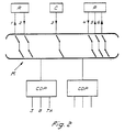
- the concept for the equipment illustrated contains functions for the control, monitoring and administration of the network, which is shown clearly in Figure 2.
- the pieces of path selection equipment connected to the network K in Figure 1 are indicated in Figure 2 by the designation R.
- the pieces of conversion equipment and the processors in accordance with Figure 1 are included in a similar fashion in Figure 2 and are indicated respectively by the designations C and P.
- the central monitoring organs in the network are symbolized by CDP (Central Monitoring Processors).
- Control paths 1-6 are indicated by arrows.
- the arrow 1 indicates the possibility for changing the path selection information, the blocking of certain traffic and/or the allocation of priority to certain traffic via the pieces of equipment R.
- the arrow 2 indicates availability information and/or traffic statistics from the path selection equipment.
- the arrow 3 indicates availability information and/or traffic statistics from the conversion equipment, whereas the arrow4 indicates corresponding information or statistics from the processors P.
- the processors can also be controlled so as to allocate priority to certain traffic, as indicated by the arrow 5.
- the interruption of certain connections, for example those with low priority, can also be controlled; see the arrow 6.
- the central monitoring processors may be of a previously disclosed type and may include connections for a printer S, a screen B and a keyboard TA, etc.
- Changes to traffic path information shall be capable of being made from appropriate central points in the network, cf. CDP, which will arrive at the pieces of path selection equipment R via separate selectors.
- the terminals and the operators must identify themselves to the path selection equipment R so that the latter can select a path of, if necessary, block traffic on the basis of its origin.
- Processors and pieces of conversion equipment shall meter their traffic continuously and shall notify blocking situations to the central monitoring points of the network, which in turn control the operation of the path selection equipment.
- the path selection equipment shall be able to communicate with the central monitoring points of the network and shall notify any communication requirements which cannot be executed. The possibility shall be afforded of interrupting connections of low priority via the processors from a central point in the network, should the information from the path selection equipment so require.
Landscapes
- Engineering & Computer Science (AREA)
- Theoretical Computer Science (AREA)
- Physics & Mathematics (AREA)
- Computer Networks & Wireless Communication (AREA)
- General Physics & Mathematics (AREA)
- General Engineering & Computer Science (AREA)
- Signal Processing (AREA)
- Computer Hardware Design (AREA)
- Computer Security & Cryptography (AREA)
- Mathematical Physics (AREA)
- Software Systems (AREA)
- Data Exchanges In Wide-Area Networks (AREA)
- Telephonic Communication Services (AREA)
- Computer And Data Communications (AREA)
Claims (10)
Applications Claiming Priority (1)
| Application Number | Priority Date | Filing Date | Title |
|---|---|---|---|
| SE8305037A SE438924B (sv) | 1983-09-20 | 1983-09-20 | Anordning for vegval i kommunikationsnet |
Publications (2)
| Publication Number | Publication Date |
|---|---|
| EP0197930A1 EP0197930A1 (de) | 1986-10-22 |
| EP0197930B1 true EP0197930B1 (de) | 1988-01-27 |
Family
ID=20352554
Family Applications (1)
| Application Number | Title | Priority Date | Filing Date |
|---|---|---|---|
| EP84904186A Expired EP0197930B1 (de) | 1983-09-20 | 1984-10-23 | Anordnung zur wegeauswahl in einem nachrichtennetz |
Country Status (3)
| Country | Link |
|---|---|
| EP (1) | EP0197930B1 (de) |
| SE (1) | SE438924B (de) |
| WO (1) | WO1986002751A1 (de) |
Families Citing this family (2)
| Publication number | Priority date | Publication date | Assignee | Title |
|---|---|---|---|---|
| JP2529775B2 (ja) * | 1990-11-28 | 1996-09-04 | 富士通株式会社 | 伝送路選択方式 |
| JP2503142B2 (ja) * | 1991-04-18 | 1996-06-05 | インターナショナル・ビジネス・マシーンズ・コーポレイション | ソフトウェアモジュ―ル能力の自動決定方法及び装置 |
Family Cites Families (1)
| Publication number | Priority date | Publication date | Assignee | Title |
|---|---|---|---|---|
| US4099235A (en) * | 1972-02-08 | 1978-07-04 | Siemens Aktiengesellschaft | Method of operating a data processing system |
-
1983
- 1983-09-20 SE SE8305037A patent/SE438924B/sv not_active IP Right Cessation
-
1984
- 1984-10-23 WO PCT/SE1984/000350 patent/WO1986002751A1/en not_active Ceased
- 1984-10-23 EP EP84904186A patent/EP0197930B1/de not_active Expired
Also Published As
| Publication number | Publication date |
|---|---|
| SE8305037D0 (sv) | 1983-09-20 |
| EP0197930A1 (de) | 1986-10-22 |
| WO1986002751A1 (en) | 1986-05-09 |
| SE8305037L (sv) | 1985-03-21 |
| SE438924B (sv) | 1985-05-13 |
Similar Documents
| Publication | Publication Date | Title |
|---|---|---|
| CA1206269A (en) | Communication bus interface unit | |
| US4982325A (en) | Applications processor module for interfacing to a database system | |
| US5107260A (en) | Method and arrangement for transmitting data between a central data station and a plurality of data terminals in a local area network | |
| EP0200721B1 (de) | Anordnung zur datenübertragung zwischen zu verschiedenen netzwerkarchitekturen gehörenden geräten | |
| US6154449A (en) | Switchless network | |
| WO1986002751A1 (en) | Arrangement for path selection in a communications network | |
| US4511759A (en) | Apparatus for controlling transfers of files between computers | |
| JPS62125746A (ja) | 交換システム内情報伝達制御方式 | |
| JPH1169394A (ja) | プロトコル制御用メモリの共有化方法 | |
| CA1253938A (en) | Arrangement for path selection in a communications network | |
| JPH0634351U (ja) | 異なったネットワークアーキテクチャに属する設備間の通信構造 | |
| CA1246726A (en) | Arrangement for communication between equipment belonging to different network architectures | |
| JPH0426144B2 (de) | ||
| KR970002753B1 (ko) | 분산처리 구조방식의 출중계선 선택 제어방법 | |
| Matteson | Computer Processing for Data Communications | |
| KR920003832B1 (ko) | 통신 버스 인터페이스 장치 | |
| JPH0311858A (ja) | ダイヤル発信装置 | |
| JPH0115195B2 (de) | ||
| JPH04264853A (ja) | データ通信方式 | |
| JPH0344197A (ja) | 多元多重交換接続方式 | |
| JPH02271747A (ja) | ファクシミリ蓄積交換装置 | |
| JPS63141429A (ja) | パケツト多重化装置 | |
| KR20030018472A (ko) | 이동통신 시스템의 연결로드 할당장치 | |
| JPS62104298A (ja) | 電話交換システムにおける負荷分散方式 | |
| JPH0470151A (ja) | データ伝送装置 |
Legal Events
| Date | Code | Title | Description |
|---|---|---|---|
| PUAI | Public reference made under article 153(3) epc to a published international application that has entered the european phase |
Free format text: ORIGINAL CODE: 0009012 |
|
| 17P | Request for examination filed |
Effective date: 19860610 |
|
| AK | Designated contracting states |
Kind code of ref document: A1 Designated state(s): DE FR GB |
|
| 17Q | First examination report despatched |
Effective date: 19861223 |
|
| GRAA | (expected) grant |
Free format text: ORIGINAL CODE: 0009210 |
|
| AK | Designated contracting states |
Kind code of ref document: B1 Designated state(s): DE FR GB |
|
| REF | Corresponds to: |
Ref document number: 3469079 Country of ref document: DE Date of ref document: 19880303 |
|
| ET | Fr: translation filed | ||
| PLBE | No opposition filed within time limit |
Free format text: ORIGINAL CODE: 0009261 |
|
| STAA | Information on the status of an ep patent application or granted ep patent |
Free format text: STATUS: NO OPPOSITION FILED WITHIN TIME LIMIT |
|
| 26N | No opposition filed | ||
| PGFP | Annual fee paid to national office [announced via postgrant information from national office to epo] |
Ref country code: FR Payment date: 19970912 Year of fee payment: 14 |
|
| PGFP | Annual fee paid to national office [announced via postgrant information from national office to epo] |
Ref country code: GB Payment date: 19971009 Year of fee payment: 14 |
|
| PG25 | Lapsed in a contracting state [announced via postgrant information from national office to epo] |
Ref country code: GB Free format text: LAPSE BECAUSE OF NON-PAYMENT OF DUE FEES Effective date: 19981023 |
|
| PGFP | Annual fee paid to national office [announced via postgrant information from national office to epo] |
Ref country code: DE Payment date: 19981231 Year of fee payment: 15 |
|
| GBPC | Gb: european patent ceased through non-payment of renewal fee |
Effective date: 19981023 |
|
| PG25 | Lapsed in a contracting state [announced via postgrant information from national office to epo] |
Ref country code: FR Free format text: LAPSE BECAUSE OF NON-PAYMENT OF DUE FEES Effective date: 19990630 |
|
| REG | Reference to a national code |
Ref country code: FR Ref legal event code: ST |
|
| PG25 | Lapsed in a contracting state [announced via postgrant information from national office to epo] |
Ref country code: DE Free format text: LAPSE BECAUSE OF NON-PAYMENT OF DUE FEES Effective date: 20000801 |