EP0197894A2 - Assembly including a modular electrical or electronic circuit, and a connector for linking the circuit to an autonomous electrical system - Google Patents
Assembly including a modular electrical or electronic circuit, and a connector for linking the circuit to an autonomous electrical system Download PDFInfo
- Publication number
- EP0197894A2 EP0197894A2 EP86810156A EP86810156A EP0197894A2 EP 0197894 A2 EP0197894 A2 EP 0197894A2 EP 86810156 A EP86810156 A EP 86810156A EP 86810156 A EP86810156 A EP 86810156A EP 0197894 A2 EP0197894 A2 EP 0197894A2
- Authority
- EP
- European Patent Office
- Prior art keywords
- housing
- shoe
- tongue
- recess
- tracks
- Prior art date
- Legal status (The legal status is an assumption and is not a legal conclusion. Google has not performed a legal analysis and makes no representation as to the accuracy of the status listed.)
- Withdrawn
Links
Images


Classifications
-
- H—ELECTRICITY
- H01—ELECTRIC ELEMENTS
- H01R—ELECTRICALLY-CONDUCTIVE CONNECTIONS; STRUCTURAL ASSOCIATIONS OF A PLURALITY OF MUTUALLY-INSULATED ELECTRICAL CONNECTING ELEMENTS; COUPLING DEVICES; CURRENT COLLECTORS
- H01R12/00—Structural associations of a plurality of mutually-insulated electrical connecting elements, specially adapted for printed circuits, e.g. printed circuit boards [PCB], flat or ribbon cables, or like generally planar structures, e.g. terminal strips, terminal blocks; Coupling devices specially adapted for printed circuits, flat or ribbon cables, or like generally planar structures; Terminals specially adapted for contact with, or insertion into, printed circuits, flat or ribbon cables, or like generally planar structures
- H01R12/50—Fixed connections
- H01R12/59—Fixed connections for flexible printed circuits, flat or ribbon cables or like structures
- H01R12/592—Fixed connections for flexible printed circuits, flat or ribbon cables or like structures connections to contact elements
-
- H—ELECTRICITY
- H01—ELECTRIC ELEMENTS
- H01R—ELECTRICALLY-CONDUCTIVE CONNECTIONS; STRUCTURAL ASSOCIATIONS OF A PLURALITY OF MUTUALLY-INSULATED ELECTRICAL CONNECTING ELEMENTS; COUPLING DEVICES; CURRENT COLLECTORS
- H01R12/00—Structural associations of a plurality of mutually-insulated electrical connecting elements, specially adapted for printed circuits, e.g. printed circuit boards [PCB], flat or ribbon cables, or like generally planar structures, e.g. terminal strips, terminal blocks; Coupling devices specially adapted for printed circuits, flat or ribbon cables, or like generally planar structures; Terminals specially adapted for contact with, or insertion into, printed circuits, flat or ribbon cables, or like generally planar structures
- H01R12/70—Coupling devices
- H01R12/82—Coupling devices connected with low or zero insertion force
- H01R12/85—Coupling devices connected with low or zero insertion force contact pressure producing means, contacts activated after insertion of printed circuits or like structures
- H01R12/89—Coupling devices connected with low or zero insertion force contact pressure producing means, contacts activated after insertion of printed circuits or like structures acting manually by moving connector housing parts linearly, e.g. slider
-
- H—ELECTRICITY
- H01—ELECTRIC ELEMENTS
- H01L—SEMICONDUCTOR DEVICES NOT COVERED BY CLASS H10
- H01L2924/00—Indexing scheme for arrangements or methods for connecting or disconnecting semiconductor or solid-state bodies as covered by H01L24/00
- H01L2924/0001—Technical content checked by a classifier
- H01L2924/0002—Not covered by any one of groups H01L24/00, H01L24/00 and H01L2224/00
-
- H—ELECTRICITY
- H01—ELECTRIC ELEMENTS
- H01R—ELECTRICALLY-CONDUCTIVE CONNECTIONS; STRUCTURAL ASSOCIATIONS OF A PLURALITY OF MUTUALLY-INSULATED ELECTRICAL CONNECTING ELEMENTS; COUPLING DEVICES; CURRENT COLLECTORS
- H01R29/00—Coupling parts for selective co-operation with a counterpart in different ways to establish different circuits, e.g. for voltage selection, for series-parallel selection, programmable connectors
Abstract
Cet ensemble comprend, disposé dans un boîtier (1 à 3), un PC-board (4) auquel est fixée une lame ressort (5) et faisant saillie dans un évidement (11) du boîtier. La face inférieure du PC-board est revêtue de pistes conductrices aboutissant des "puces" destinées à être reliées galvaniquement à un système électrique indépendant par contact avec des pistes conductrices homologues (?) associées à ce système. Le fléchissement du PC-board nécessaire à l'établissement de ce contact est obtenu par déplacement en direction Ø1 d'un sabot (7), lequel repousse un barreau cylindrique (8), disposé librement dans une fente (9) et reposant sur le complexe lame ressort (5) - PC-board (4). Un déplacement de ce sabot (7) en direction Ø2 commande l'interruption du contact entre les deux séries de pistes conductrices.This assembly comprises, disposed in a housing (1 to 3), a PC-board (4) to which is fixed a leaf spring (5) and projecting into a recess (11) of the housing. The underside of the PC-board is coated with conductive tracks leading to "chips" intended to be galvanically connected to an independent electrical system by contact with homologous conductive tracks (?) Associated with this system. The deflection of the PC-board necessary for the establishment of this contact is obtained by displacement in direction Ø1 of a shoe (7), which pushes back a cylindrical bar (8), freely placed in a slot (9) and resting on the leaf spring complex (5) - PC-board (4). A displacement of this shoe (7) in direction Ø2 controls the interruption of the contact between the two series of conductive tracks.
Description
Commeon le sait, les installations et appareils à fonctionnement électronique sont constitués aujourd'hui, aans leur quasi totalité, par assemblage a'une pluralité de cartes amovibles, et donc interchangeables, généralement formées par un circuit imprimé faisant support pour un ou plusieurs circuits électroniques, par exemple des circuits intégrés, branchés sur ce circuit, voire couplés entre eux par l'intermédiaire d'un tel circuit. A l'intérieur a'une même installation ou appareil, ces cartes sont couplées entre elles par l'intermédiaire d'un ensemble de barres "bus" auxquelles elles sont reliées galvaniquement par des systèmes de connecteurs aussi aivers que nombreux, généralement de mise en oeuvre assez complexe, interdisant pratiquement à tout usager néophyte de procéder de lui-uê- me au remplacement a'une carte par une autre. De plus, un tel remplacement ne peut généralement avoir lieu qu'en accédant au coeur même de l'installation ou appareil en question.As we know, installations and apparatuses with electronic functioning are constituted today, almost entirely, by assembling to a plurality of removable and therefore interchangeable cards, generally formed by a printed circuit making support for one or more electronic circuits , for example integrated circuits, connected to this circuit, or even coupled together via such a circuit. Inside a same installation or device, these cards are coupled to each other by means of a set of "bus" bars to which they are galvanically connected by connector systems as wide as many, generally implemented. rather complex work, prohibiting practically any neophyte user to proceed to replace one card with another. In addition, such a replacement can generally only take place by accessing the very heart of the installation or device in question.
L'apparition des jeux électroniques et des mini-ordinateurs à usage domestique a conduit les constructeurs à prévoir la possibilité, pour les usagers, ae procéder eux-mêmes à la substitution de certaines cartes portant des circuits donnés, concernant par exemple des programmes informatisés, sans devoir ni opérer à l'intérieur du boîtier de ces appareils ni faire usage d'outils particuliers. C'est ainsi qu'on a aisposé ces cartes sous enveloppe rigide ae protection, enfichable sur une partie du boîtier prévue à cet effet, les liaisons de nature électrique étant réalisées à l'aide de connecteurs appropriés dont l'architecture ne limite d'ailleurs pas leur emploi dans le contexte ci-dessus mais est également souvent valable pour assurer le branchement électrique de "cartes électroniques" traditionnelles, telles celles mentionnées précèdenment.The appearance of electronic games and mini-computers for domestic use has led manufacturers to provide for the possibility, for users, to proceed themselves to the substitution of certain cards carrying given circuits, for example concerning computerized programs, without having to either operate inside the housing of these devices or make use of special tools. This is how these cards were placed in a rigid protective envelope, which can be plugged into a part of the housing provided for this purpose, the electrical connections being made using appropriate connectors whose architecture does not limit elsewhere not their use in the above context but is also often valid for ensuring the electrical connection of traditional "electronic cards", such as those mentioned above.
La présente invention vise à permettre une généralisation d'emploi de ce principe des "cartes électroniques" et propose, a cet effet, un ensemble englobant un circuit modulaire électrique ou électronique et un connecteur aestiné à relier ce circuit à un système électrique autonane, cet ensemble comprenant, came les ensembles similaires connus, un boîtier, contenant tant ledit circuit que le connecteur, et aes moyens pour fixer amoviblement le boîtier au sys- tèem dans une position autorisant ladite liaison galvanique entre une première pluralité ae pistes conductrices, rattachées électriquement aux points du circuit à relier au système, et une secconde pluralité de pistes conductrices homologues appartenant à ce système.The present invention aims to allow a generalization of use of this principle of "electronic cards" and proposes, for this purpose, an assembly including a modular electric or electronic circuit and a connector designed to connect this circuit to a system electric autonane, this assembly comprising, cam known similar assemblies, a housing, containing both said circuit and the connector, and its means for removably fixing the housing to the system in a position allowing said galvanic connection between a first plurality of conductive tracks , electrically attached to the points of the circuit to be connected to the system, and a second plurality of homologous conductive tracks belonging to this system.
Un tel ensemble modulaire doit, en effet, présenter une architecture générale simple, être particulièrement fiable, bon marché et de dimensions particulièrement réduites, notamment en ce qui concerne l'épaisseur. L'ensemble selon l'invention aoit, en effet, pouvoir être associé à un ordinateur de poche, ou genre décrit par exemple dans la demande de brevet européen No. 0 053 061, c'est-à-dire un ordinateur de très faible encombrement puisque ses dimensions ma- xiimm sont généralement de l'ordre de 20 cm ae longueur x il cm ae largeur, x 2,5 à 3 cm d'épaisseur. Malgré une épaisseur aussi faible, un tel ordinateur englobe notamment un clavier ae type "transparent touch sensitive", occupant pratiquement toute la surface de l'une des ceux faces principales du boîtier ae l'ordinateur, et une cellule d'affichage a cristaux liquides (LCD) idposée sous le clavier, le tout étant placé aans le boîtier, au-dessus aes nombreux circuits électroniques nécessaires à la marche de l'orainateur, dont l'ensemble présente tout de même oe 1 à 1,5 cm d'épaisseur. C'est dire que la place disponible, aans le sens de l'épaisseur de l'ordinateur, pour un ensemble du genre ci-dessus, destiné à être fixé au boîtier, du côté opposé à la face portant le clavier, est particulièrement réduite et ne aépasse guère 3 mm environ. Malgré une épaisseur exceptionnellement limitée, l'ensemble en question doit englober dans son boîtier un mécanisme d'actionnement manuel, ae structure miniaturisée, de la mise en service et hors service du circuit modulaire électrique ou électronique, lui aussi intégré au boîtier, et qui doit en outre effectuer, simultanément, le verrouillage de cet ensemble sur le système autonome auquel il est destiné a être branché électriquement, dans la position en service" du circuit.Such a modular assembly must, in fact, have a simple general architecture, be particularly reliable, inexpensive and of particularly reduced dimensions, in particular as regards the thickness. The assembly according to the invention should, in fact, be able to be associated with a pocket computer, or genre described for example in European patent application No. 0 053 061, that is to say a computer of very low size since its maximum dimensions are generally of the order of 20 cm in length x it in width, x 2.5 to 3 cm in thickness. Despite such a small thickness, such a computer includes in particular a keyboard of the “transparent touch sensitive” type, occupying practically the entire surface of one of those main faces of the housing of the computer, and a liquid crystal display cell. (LCD) placed under the keyboard, the whole being placed in the housing, above the numerous electronic circuits necessary for the operation of the speaker, the assembly nevertheless having a thickness of 1 to 1.5 cm . This means that the space available, in the sense of the thickness of the computer, for a set of the above type, intended to be fixed to the case, on the side opposite to the face carrying the keyboard, is particularly reduced. and hardly exceeds 3 mm approximately. Despite an exceptionally limited thickness, the assembly in question must include in its housing a manual actuation mechanism, with a miniaturized structure, of the putting into and out of service of the modular electric or electronic circuit, which is also integrated in the case, and which must also perform, simultaneously, the locking of this assembly on the autonomous system to which it is intended to be electrically connected, in the operating position "of the circuit.
Les aemandes EP 858100014.2 et EP 85900608.2 aécrivent déjà un ensemble modulaire répondant aux critères ci-dessus: s'agissant ae demandes ne aésignant que l'Italie, la France et le Royaume Uni, la requérante a procédé de sa propre initiative à une limitation et présenté deux jeux de revendications distincts, l'un (A), valable pour les désignations de l'Italie, de la France et du Royaume Uni, rédigé en application de l'Art. 54 (3) CBE, l'autre (B), valable pour les désignations ae l'Autriche, ae la Belgique, du Luxembourg, aes Pays-Bas, de la République Fédérale d'Allemagne, de la Suède et de la Suisse, pays aans lesquels les demandes de brevet européen ci-dessus ne constituent pas des antériorités quant à la nouveauté opposables au jeu de revendications concerné par ces pays.The German applicants EP 858100014.2 and EP 85900608.2 already write a modular unit meeting the above criteria: with regard to the requests which only cover Italy, France and the United Kingdom, the applicant proceeded on her own initiative to a limitation and presented two distinct sets of claims, one (A), valid for the designations of Italy, France and the United Kingdom, drawn up in application of Art. 54 (3) EPC, the other (B), valid for designations to Austria, Belgium, Luxembourg, the Netherlands, the Federal Republic of Germany, Sweden and Switzerland, countries in which the above European patent applications do not constitute prior art as regards the novelty opposable to the set of claims concerned by these countries.
L'identité et l'étenaue de l'invention concernée par la présente demande ae brevet sont aonc données par les deux jeux de revendications de la aemande auxquels on se reportera directement pour plus de détails.The identity and the scope of the invention concerned by the present patent application are given by the two sets of claims of the application to which we will refer directly for more details.
D'autres particularités et caractéristiques de la présente invention seront maintenant décrites en se référant aux dessins annexés, cannés à titre d'exemple, aans lesquels:
- la fig. 1 est une vue en perspective, de dessus, d'un ordinateur de poche;
- la fig. 2 est une vue en perspective, ae dessous, de l'ordinateur représenté sur la fig. l;
- la fig. 3 est une vue en coupe verticale, à plus grande échelle, selon III-III de la fig. 2, illustrant les éléments structurels du connecteur aont est muni l'ensemble modulaire selon une première forme d'exécution de l'invention;
- la fig. 4 est une vue similaire à celle de la fig. 3, dans une autre position de certains éléments du connecteur;
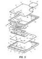
- la fig. 5 est une vue éclatée, en perspective, montrant une partie des éléments de l'ensemble;
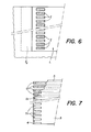
- la fig. b est une vue de détail, selon VI-VI ae la fig. 3;
- la fig. 7 est une autre vue de aétail ce cette même fig. 3, selon l'axe VII-VII, avec arrachement partiel de certains éléments.
- fig. 1 is a perspective view, from above, of a handheld computer;
- fig. 2 is a perspective view, below, of the computer shown in FIG. l;
- fig. 3 is a view in vertical section, on a larger scale, along III-III of FIG. 2, illustrating the structural elements of the connector aont is provided with the modular assembly according to a first embodiment of the invention;
- fig. 4 is a view similar to that of FIG. 3, in another position of certain elements of the connector;
- fig. 5 is an exploded perspective view showing part of the elements of the assembly;
- fig. b is a detailed view, according to VI-VI ae fig. 3;
- fig. 7 is another detailed view of this same fig. 3, along the axis VII-VII, with partial tearing of certain elements.
L'orainateur représenté sur les figs 1 et 2 est un ordinateur de poche, d'un type semblable à celui décrit dans la aemande de brevet européen No. 0 053 061, c'est-à-dire un ordinateur aux dimensions particulièrement réduites (20 x 11 x 3 cm environ) pour une qualité de prestations exceptionnellement élevée dans un volume aussi fai- ole.The computer shown in FIGS. 1 and 2 is a pocket computer, of a type similar to that described in European patent application No. 0 053 061, that is to say a computer with particularly reduced dimensions ( 20 x 11 x 3 cm approximately) for an exceptionally high quality of service in such a small volume.
La face supérieure d'un tel ordinateur présente, dans sa partie centrale, un écran rectangulaire E englobant un clavier de type "transparent touch sensitive" et une cellule a'affichage à cristaux liquides (LCD) disposée sous le clavier, écran qui est entouré par une ceinture C de touches ae contrôle et a'actionnement de l'ordinateur. Sur sa tranche, l'ordinateur illustré comporte divers boutons de réglage (Rl, R2) et poussoirs de commande, soit un poussoir (Pl) pour l'enclenchement de l'ordinateur, un secona poussoir (P2) pour son déclenchement et un troisième poussoir (P3) ae réinitiali- sation du système de l'ordinateur, des prises (Fl à F4) permettant le branchement a'appareils divers (microphane, lecteur ae cassettes, écouteur par exemple), une sortie série RS 232 aevant permettre le branchement ae périphériques, telle une imprimante par exemple, une prise femelle PF pour le branchement de l'ordinateur sur une source d'alimentation extérieure, un passage PS, ménagé aans le boîtier de l'appareil pour une courroie de préhension (non representee), un connecteur parallèle CP, a 40 broches, pour le branchement de l'orainateur à un moaem, à une imprimante ou à un appareil de mesure par exenple, l'ouverture d'un compartiment destiné à recevoir des fils a'alimentation de l'ordinateur, ouverture non visible au dessin car masquée par un couvercle CP monté coulissant dans une rainure RA creusée aans le boîtier, ce couvercle étant ainsi susceptible a'être conduit de la position représentée, d'obturation du compartiment des piles, dans une seconde position, décalée par rapport à la première, dans laquelle l'usager peut avoir accès à ce compartiment, notamment pour procéder au remplacement ces piles usagées. Sur sa ta- ce opposée à celle munie de l'écran E, l'ordinateur représenté comporte un poussoir PR permettant de cmmander la fonction RESET de l'ordinateur, un haut parleur HP et quatre logements Ll a L4 aesti- nés a recevoir un nombre correspondant a'ensembles amovibles El a E4 dont les particularités structurelles seront illustrées ci-après et formant autant de "cartes mémoires" RAM et/ou ROM, susceptibles de constituer aes mémoires ae stockage a'informations générées a l'aide de l'ordinateur et/ou des mémoires compoirtant ces programmes utilitaires de toute nature.The upper face of such a computer has, in its central part, a rectangular screen E including a keyboard of the "transparent touch sensitive" type and a cell with liquid crystal display (LCD) arranged under the keyboard, screen which is surrounded by a belt C of keys for control and actuation of the computer. On its edge, the illustrated computer has various adjustment buttons (Rl, R2) and control push buttons, either a push button (Pl) for switching on the computer, a second push button (P2) for starting it and a third push button (P3) to reset the computer system, sockets (Fl to F4) allowing connection to various devices (microphane, cassette player, earphone for example), an
L'orainateur comporte, de plus, aans la portion de volume ae son boîtier comprise, en substance, entre l'écran E et les logements Ll à L4, notamment l'ensemble des circuits logiques et connexions nécessaires tant au fonctionnement du clavier et de l'affichage qu'à la gestion et à l'exécution des aiverses fonctions propres à l'ordinateur. Tous ces éléments n'ayant pas un rapport airect avec les caractéristiques essentielles de l'ensemble selon l'invention n'ont pas été représentés et ne seront pas décrits.The computer comprises, moreover, in the volume portion of its housing included, in essence, between the screen E and the housings L1 to L4, in particular all of the logic circuits and connections necessary both for the operation of the keyboard and the display and for the management and execution of the various functions specific to the computer. All these elements not having a direct relationship with the essential characteristics of the assembly according to the invention have not been shown and will not be described.
comme inaiqué, l'orainateur visible aux figs 1 et 2 fait notamment emploi de cartes-mémoire El à E4 qui sont destinées à être in- troduites de façon amovible à l'intérieur des logements correspondants Ll a L4, ménagés aans le boîtier de l'orainateur, cartes destinées a être connectées électriquement à cet ordinateur en vue soit d'en compléter l'importance de la mémoire de travail, soit d'avoir accès à des programmes ou à des parties de programmes particuliers, inexistants aans la mémoire résidante de l'appareil. comme déjà inaiqué, s'agissant alun orainateur portatif de dimensions particulièrement faibles, les cartes-mémoire ci-dessus doivent présenter ces dimensions réduites, de l'ordre de 55 x 45 mm de côté et a'environ 3 mm d'épaisseur, et pouvoir être fixées sur l'ordinateur (ou séparées de celui-ci) manuellement, sans faire usage d'outils particuliers, leur branchement électrique devant être irréprochable et demeurer tel quelque puissent être les mouvements et les modifications ce position que l'ordinateur puisse être appelé a connaître.as inaiqué the orainateur visible in Figs 1 and 2 is of particular use memory cards El to E4 which are intended to be in - troduites removably inside the corresponding housings Ll to L4 formed aans the housing of the 'orator, cards intended to be electrically connected to this computer in order either to supplement the importance of the working memory, or to have access to specific programs or parts of programs, nonexistent in the resident memory of the device. as already mentioned, in the case of a portable organizer of particularly small dimensions, the above memory cards must have these reduced dimensions, of the order of 55 x 45 mm on a side and about 3 mm thick, and be able to be fixed on the computer (or separated from it) manually, without making use of particular tools, their electrical connection having to be flawless and remaining such whatever the movements and modifications may be this position that the computer can be called to know.
A cet effet, l'invention propose un ensemble englobantun circuit modulaire électrique ou électronique et un connecteur destiné a permettre de relier galvaniquement ce circuit à un système électrique autonome, même différent d'un ordinateur. On pourrait notamment en faire usage dans des appareils portatifs a'autre nature, radio ou téléviseurs par exenple, dans des tableaux ae commande d'installations diverses, dans des centraux téléphoniques, aes stations de télécommunication etc..To this end, the invention provides an assembly encompassing a modular electric or electronic circuit and a connector intended to allow galvanic connection of this circuit to an autonomous electrical system, even different from a computer. One could in particular make use of it in portable apparatuses of other nature, radio or televisions for example, in panels with control of various installations, in telephone exchanges, telecommunication stations etc.
Comme on le voit sur la fig. l, l'ensemble modulaire El est destiné à être inséré dans le logement Ll de l'orainateur en vue a'être relié galvaniquement a celui-ci par l'intermédiaire de barres/bus e dont seules une vingtaine d'entre elles ont été représentées pour ne pas charger inutilement la figure.As seen in fig. l, the modular assembly El is intended to be inserted into the housing Ll of the computer speaker with a view to being galvanically connected thereto by means of bars / bus e of which only about twenty of them have been shown so as not to load the figure unnecessarily.
Sur la fig. 2, on distingue les éléments structurels dont est muni l'ensemble modulaire E2 à peine introduit dans son logement L2 (élément qui est structurellement iaentique à l'élément El ci-aes- sus), en vue ce permettre, a la fois, la liaison galvanique mentionnée et le blocage mécanique de cet ensemble aans son logement.In fig. 2, a distinction is made between the structural elements with which the modular assembly E2 is barely introduced in its housing L2 (element which is structurally iaent to element El above), in order to allow this, both, the galvanic connection mentioned and the mechanical blocking of this assembly in its housing.
Un tel ensemble est obtenu, en substance, par superposition et assemblage ces diverses pièces qui vont maintenant être décrites en se référant plus particuliièrrement aux figures 3 à 7 des aessins annexés. Il comporte (tig. 5) un boîtier formé d'une embase rectangulaire 1 sur laquelle repose un cadre 2 dont l'ouverture est obturée par un couvercle 3. Entre l'embase 1 et le caare 2, l'ensemble illustré présente une plaque 4, en matériau isolant souple, constituant un circuit imprimé, ou PC board, sur lequel sont fixées les "puces" des circuits logiques propres à chaque ensemble, puces qui n'ont pas été représentées mais qui prennent place aans le volume P laissé libre entre cette plaque 4, le cadre 2, le couvercle 3 et une masse de remplissage M, de résine epoxy par exemple (figs 3 et 4).Such an assembly is obtained, in essence, by superimposing and assembling these various parts which will now be described with particular reference to Figures 3 to 7 of the accompanying drawings. It comprises (tig. 5) a housing formed by a
Les quatre éléments 1 a 4 sont assemblés par le moyen de vis (non représentées) faisant prise dans des ouvertures 1'et 1" de l'embase 1 et traversant dess passages correspondants 2' et 2", 3' et 3", 4' et 4", ménagés respectivement dans les éléraents 2, 3 et 4. En variante, le même assemblage pourrait être réalisé par des chevilles en matériau thermofusible faisant saillie par exemple aux endroits occupés par les ouvertures 1' de l'embase 1 et ocnt on provoquerait la fusion de l'extrémité supérieure au terme du montage pour former une tête de serrage. Il convient, à ce point, de relever que tant l'embase 1 que le cadre 2 seront de préférence réalisés en matière plastique moulée, par exemple en ABS dopée de téflon; en ce qui concerne le couvercle 3, celui-ci sera par contre obtenu par étampage d'une feuille d'acier inoxydable.The four
Comme on le voit sur la fig. 5, les ouvertures 1" de l'embase 1 sont pratiquées dans des bossages cylinariques la et lb faisant saillie sur le fond de l'embase, à proximité immédiate au bord postérieur d'une fenêtre lf, ces bossages formant organe de positionnement pour le PC-board 4, par engagement dans des ouvertures 4a et 4b, pour un peigne-ressort 5, respectivement pour une traverse 6, par engagement dans des ouvertures 5a et 5b, respectivement 6a et 6b. Aux figs 3 et 4, la position ae ces bossages est marquée par la représentation de leur axe de symétrie A-A.As seen in fig. 5, the
Les bossages la et lb constituent, de plus, des organes de positionnement et ae guidage dans ses déplacements rectilignes possibles, en direction ∅1 ou ∅2, pour un sabot 7 par engagement dans des ouvertures oblongues 7a et 7b, orientées selon l'axe ∅1-∅2. La longueur de ces ouvertures, 7a et 7b, et le diamètre des bossages la et lb de l'embase 1 déterminent l'amplitude du aéplacement axial possible pour le sabot 7, en direction ∅1-∅2.The bosses 1a and 1b constitute, in addition, positioning members and a guide in its possible rectilinear displacements, in direction ∅1 or ∅2, for a
Ce sabot est muni alun rostre lamelliforme 7c (figs 3 à 5), découpé par trois fentes parallèles 7d tormant autant de moyens ae préhension devant permettre à un usager de commander, par exemple du doigt, le coulissement au sabot d'une première position limite, ae retrait (fig. 3), dans une seconde position limite, saillante (fig. 4), aans laquelle le rostre 7c vient s'engager dans une fente réceptrice t2 que présente la paroi latérale de chaque logement Ll à L4 de l'ordinateur.This shoe is provided with a
Revenons à l'embase 1: comme on le voit plus particulièrement sur les figs 3 a 5, le pourtour extérieur de cette embase présente un profil en chevron sur ceux côtés adjacents, lc et ld, et un profil rainuré homologue sur ses deux autres côtés, le et 1t. En effet, tout ensemble El et E4 ne peut être introduit dans le logement correspondant, L1. à L4, de l'oràinateur que par coulissement aans le sens λ1, dans une rainure ℓ3, pour le côté lc, et sur une glissière ℓ4, pour le côté le de forme homologue, prévues sur les bords longitudinaux de chaque logement Ll à L4. C'est seulement au terme d'un tel engagement que l'usager peut verrouiller les ensembles El à E4 dans leurs logements respectifs Ll a L4 en déplaçant le rostre 7c de chaque ensemble considéré de la manière décrite ci-dessus (coulissement en direction Ø1-fig. 5). L'extraction de l'un ou be l'autre de ces ensembles s'effectuera en déplaçant le rostre en airec- tion Ø2 (fig. 5) , opposée à la première, et en commandant ensuite un déplacement de l'ensemble en airectionλ 2 (fig. 2).Returning to base 1: as seen more particularly in FIGS. 3 to 5, the outer periphery of this base has a chevron profile on those adjacent sides, lc and ld, and a homologous grooved profile on its two other sides. , le and 1t. Indeed, any set El and E4 cannot be introduced into the corresponding housing, L1. to L4, from the computer that by sliding in the direction λ1, in a groove ℓ3, for the side lc, and on a slide ℓ4, for the side of homologous shape, provided on the longitudinal edges of each housing Ll to L4 . It is only at the end of such a commitment that the user can lock the assemblies El to E4 in their respective housings Ll to L4 by moving the
Aux fins précisément de permettre d'accéder commodément des doigts au rostre 7c de chaque ensemble, le caare 2 présente une découpure rectangulaire 2a, de largeur et de longueur correspondant pratiquement à la largeur et à la longueur du rostre 7c. Le couvercle 3 est également muni a'une découpure rectangulaire 3a, de aimen- sions correspondant à celles ae la aécoupure Za du cadre 2, ces aeux découpures étant positionnees de manière que, en position assemblée des eléments ae la structure représentée aux figs 3 a 5, elles soient situées exactement l'une au-dessus de l'autre, les bords de la découpure 2a embrassant le rostre 7c sur ses deux côtés longitudinaux.In order precisely to allow convenient access of the fingers to the
On remarquera encore que, aux fins d'obtenir au montage un centrage correct aes éléments 1, 2 et 3, indépendamment de l'action des vis d'assemblage dont il a été question précédemment, le cadre 2 est muni, sur sa face inférieure, d'une nervure périphérique 2b, venant s'emboiter sur le pourtour de l'ouverture supérieure 1g de 1'embase 1, et, sur sa face supérieure, a'une rainure 2c (figs 3 et 5) destinée à recevoir le bord recourbé 3b du couvercle 3. Cette nervure sert aussi a l'emboîtement d'un obturateur 3* destiné à recouvrir une batterie non représentée prenant place aans la portion de volume comprise entre le PC-board 4 (4c et 4a représentent des contacts positif et négatif auxquels se rattache la batterie), l'espace délimité par la portion du cadre 2 du coin droit supérieur de celui-ci (fig. 5) et par l'obturateur 3*. Cette batterie est en effet desti- nee à l'alimentation électrique ae "puces" électronigues portées par le PC-boara 4; elle est notamment nécessaire lorsque les puces sont aes RAM dont on veut conserver les informations mémorisées même une fois l'ensemble El à E4 correspondant éloigné de l'ordinateur. La fixation ce cet obturateur sur le couvercle 3 est effectuée par ces vis, non représentées, embrochant l'obturateur 3* au travers de passages 3*', le cadre 2 et le circuit 4 et se fixant dans l'embase 1 par engagement aans les trois ouvertures 1' situées, au dessin, aans la partie droite supérieure de cette embase.It will also be noted that, in order to obtain correct centering of the
En se référant plus particulièrement aux figs 3 et 4, on voit que, sur sa face postérieure, le côté lc ae l'embase 1 se développe en torme de latte li, d'épaisseur correspondant à celle de la traverse 6 et présentant, sur sa face supérieure, une nervure li sur laquelle prend appui le rostre 7c du sabot 7. On remarquera encore que la face inférieure de la latte li s'étend à un niveau supérieur a celui du fona de l'embase 1 d'une valeur correspondant à la somme ces épaisseurs du peigne 5 et du circuit imprimé 4.Referring more particularly to FIGS. 3 and 4, it can be seen that, on its rear face, the side lc ae the
plus aes éléments décrits, l'ensemble selon l'invention comporte en outre un barreau 8, de section circulaire, dont le diamètre, supérieur a l'épaisseur ce la traverse 6, correspond sensiblement a l'épaisseur de la latte li au niveau ae la nervure lj, et aont la longueur est identique, a la fois, a celle ce cette traverse, a celle du peigne 5 et a celle du sabot 7 tout en étant légèrement inférieure a la longueur ae la fenêtre rectangulaire lh que présente le tona de l'embase 1.plus aes elements described, the assembly according to the invention further comprises a
Ce barreau est engagé librement dans une fente rectangulaire 9, de largeur légèrement supérieure à celle du diamètre du barreau 8 et qui est aélimitée, pour ses bords longitudinaux, par la tranche de la latte li et par le bord antérieur (au aessin-fig. 5) de la traverse 6 et, pour ses bords transversaux, par aes portions des côtés Id et If de l'embase.This bar is freely engaged in a
Comme on le voit avec plus de détails sur les figs 3 et 4, le sabot 7 est engagé, par sa partie postérieure, 7e, dans une fente a section rectangulaire, 10, dont les parois sont constituées par le cadre 2, par la masse de remplissage V et par une portion de la traverse 6 sur laquelle ce sabot repose par une première partie plane 7f de la semelle, jouxtant une seconde partie 7g, à profil incliné, aboutissant au rostre 7c du sabot. A signaler que l'épaisseur de ce sabot, dans sa partie engagée dans la fente 10, est légèrement inférieure a la largeur ce cette fente de sorte que le sabot peut être déplacé par coulissement, en direction Ø1, de sa position de retrait (fig. 3) aans sa position saillante (fig. 4) ou, en direction Ø2, contraire à la première, pour ramener le sabot aans la position de retrait. Ainsi que cela a été indiqué précédemment, la course maximum susceptible d'être effectuée par le sabot 7 au cours ae ces déplacements est fixée par contact mutuel des bossages la et lb avec les ouvertures oblongues 7a et 7b déjà citées.As can be seen in more detail in FIGS. 3 and 4, the
Dans l'ensemble modulaire selon l'invention, le barreau 8 est en contact, à la fois, avec le sabot 7, par une arête longitudinale, et avec le peigne 5, par une autre arête similaire, située en position diamétralement opposée à la première arête. Il convient, à ce point, de relever que ce peigne, qui est constitué, comme aé- crit, par une lame-ressort en acier inoxyaable, est fixé, par exemple par collage, sur la face supérieure ae la portion du PC-board 4 qui est pincée entre le fond de l'embase 1 et la traverse 6 ainsi que de celle faisant librement saillie dans un logement 11. (figs 3 et 4), à proximité du fond de celui-ci, logembent qui est délimite a la fois par l'embase 1 (notamment par la nervure li et par le fond de cette embase) et par la traverse 6.In the modular assembly according to the invention, the
L'extrémité libre du peigne 5 est découpée par une série de dents 5c affaiblissant cette extrémité et lui donnant, de ce tait, une flexibilité accrue. L'écartement et la largeur ce ces cents 5c correspond en effet à l'écartement et à la largeur tant aes barres-bus apparaîssant sur le fond de chaque logement Ll à L4 de l'ordinateur (figs 2 et 6) que d'un nombre correspondant de pistes conductrices 12 dont est garnie la face inférieure au PC-board 4 (fig. 7), ces pistes s'étendant jusqu'à l'intérieur du volume V dans lequel sont disposées les puces de la carte électronique que forme l'ensemble E considere et faisant partie du circuit de couplage de ces puces.The free end of the
Dans leur portion destinée à être portée en contact avec les barres-bus ℓ, les pistes 12 sont revêtues de préférence d'une couche de contact a'un métal précieux, tel ae l'or. A titre d'exemple, on inaiquera que de telles pistes pourront présenter une largeur de l'ordre ce 8 dixièmes ae millimètre pour un écartement de l'orare de 4 dixièmes de millimètre. Elles pourraient, au besoin, même présenter ces dimensions ae valeur inférieure tout en étant assurés du maintien de leurs qualités intrinsèques pour une durée de vie particulièrement inportante. En effet, l'architecture générale de l'ensemble 5 décrit permet d'obtenir une mise en contact mutuel oes deux ensembles de pistes en présence (ℓ et 12) avec un frottement réciproque très doux et progressif dans son intensité et donc sans pro- ducticn de "scratch".In their portion intended to be brought into contact with the busbars ℓ, the
Comme on le voit sur la fig. 3, lorsque le sabot 7 est situé dans sa position limite de retrait, ce sabot délimite, en coopération avec la nervure li de l'embase 1 et la traverse 6, un espace vice Va aans lequel s'ouvre la fente 9. La hauteur de cet espace Va, le diamètre du barreau 8 ainsi que l'épaisseur de la nervure li et de la traverse 6 sont avantageusement choisies telles que, dans la position ce retrait du sabot 7 (fig. 3), ce barreau peut pénetrer partiellement dans l'espace Va sous l'action de la lame élastique formant le peigne 5 de sorte que l'ensemble formé par ce peigne et par le PC-board 4 auquel il est collé occupe alors une position pratiquement horizontale, escamotée à l'intérieur de l'évidement 11.As seen in fig. 3, when the
Si, par contre, on déplace le sabot 7 en direction Ø1, en vue de le conduire dans sa position extrême gauche, au aessin, la partie inclinée 7g de la semelle au sabot va venir en contact avec le barreau 8 et le repousser graduellement à l'intérieur de la fente 9, a rencontre de la lame élastique 5, en le faisant saillir dans l'évidement il. Comme le barreau 8 ne peut subir un tel déplacement qu'en faisant fléchir cette lame 5 et, partant, le PC-board 4 qui lui est associé, il s'ensuit que l'extrémité de ce PC-board va se rapprocher de plus en plus du fond du logement L dans lequel est engagé l'ensemble E considéré, sortir de l'évidement 11 et entrer ensuite en contact, peu a peu, par ses pistes conductrices 12 avec les pistes 1 affleurant le fond de ce logement L.If, on the other hand, the
En fin ae course au sabot 7, le PC-board occupe la position visible sur la fig. 4, dans laquelle ses propres pistes sont appliquées pratiquement sur toute la longueur des pistes ℓ citées, en exerçant une pression suffisante pour garantir un contact électrique partait. Il convient, à ce point de relever que, grâce au fait que le barreau 8 présente un profil cylindrique, le fléchissement sous l'action de ce barreau ae l'ensemble peigne 5 - PC-board 4 s'effectue ce façon particulièrement aouce, sans à-coup, le barreau étant susceptible de rouler sur lui-même, à l'intérieur de la fente 9, et sur la surface du peigne 5, contribuant ainsi à obtenir une mise en contact particulièrement douce des pistes conductrices au PC-board avec celles apparaissant sur le fond du logement L.At the end of the
Grâce à l'architecture proposée, l'ensemble selon l'invention peut être mis en place dans la rainure corresponaante sans aevoir exercer ae grands efforts; lors de cette insertion, les pistes conductrices qu'il comporte ne risquent pas d'être arrachées, celles-ci étant escamotées a l'intérieur du logement 11 de l'ensemble.Thanks to the architecture proposed, the assembly according to the invention can be put in place in the corresponding groove without having to exert with great efforts; during this insertion, the conductive tracks which it comprises are not liable to be torn off, these being retracted inside the
Claims (4)
caractérisé par le fait que le boîtier présente un évidement (11) s'ouvrant sur une portion de sa surface latérale et délimitant, sur celle-ci, une fenêtre de forme sensiblement rectangulaire, dont la position sur le boîtier est telle que, lorsque le boîtier ae l'ensemble est fixé au système par lesdits moyens, les bords de ladite fenêtre entourent au moins une portion ae la longueur de l'ensemble des secondes pistes conductrices du système,
characterized in that the housing has a recess (11) opening onto a portion of its lateral surface and delimiting thereon a window of substantially rectangular shape, the position of which on the housing is such that, when the housing to the assembly is fixed to the system by said means, the edges of said window surround at least a portion ae the length of all of the second conductive tracks of the system,
Applications Claiming Priority (2)
| Application Number | Priority Date | Filing Date | Title |
|---|---|---|---|
| CH1440/85 | 1985-04-03 | ||
| CH1440/85A CH665059A5 (en) | 1985-04-03 | 1985-04-03 | ASSEMBLY INCLUDING A MODULAR ELECTRICAL OR ELECTRONIC CIRCUIT AND A CONNECTOR FOR CONNECTING THE CIRCUIT TO A SELF - CONTAINED ELECTRICAL SYSTEM. |
Publications (2)
| Publication Number | Publication Date |
|---|---|
| EP0197894A2 true EP0197894A2 (en) | 1986-10-15 |
| EP0197894A3 EP0197894A3 (en) | 1989-05-31 |
Family
ID=4210506
Family Applications (1)
| Application Number | Title | Priority Date | Filing Date |
|---|---|---|---|
| EP86810156A Withdrawn EP0197894A3 (en) | 1985-04-03 | 1986-04-01 | Assembly including a modular electrical or electronic circuit, and a connector for linking the circuit to an autonomous electrical system |
Country Status (4)
| Country | Link |
|---|---|
| US (1) | US4723195A (en) |
| EP (1) | EP0197894A3 (en) |
| JP (1) | JPS61292716A (en) |
| CH (1) | CH665059A5 (en) |
Cited By (2)
| Publication number | Priority date | Publication date | Assignee | Title |
|---|---|---|---|---|
| EP0402613A2 (en) * | 1989-06-15 | 1990-12-19 | International Business Machines Corporation | Connector assembly with movable carriage |
| EP0475717A1 (en) * | 1990-09-12 | 1992-03-18 | Yamaichi Electric Co., Ltd. | Socket for electric part |
Families Citing this family (12)
| Publication number | Priority date | Publication date | Assignee | Title |
|---|---|---|---|---|
| US5320552A (en) * | 1990-03-17 | 1994-06-14 | Amphenol-Tuchel Electronics Gmbh | Contacting apparatus, in particular a contacting apparatus for a subscriber identity module |
| US5544007A (en) * | 1991-07-19 | 1996-08-06 | Kabushiiki Kaisha Toshiba | Card-shaped electronic device used with an electronic apparatus and having shield plate with conductive portion on a lateral side |
| US5452468A (en) | 1991-07-31 | 1995-09-19 | Peterson; Richard E. | Computer system with parallel processing for information organization |
| US6643656B2 (en) * | 1991-07-31 | 2003-11-04 | Richard Esty Peterson | Computerized information retrieval system |
| JP4057437B2 (en) * | 2003-02-04 | 2008-03-05 | 株式会社東海理化電機製作所 | Portable machine |
| JP2005039037A (en) * | 2003-07-14 | 2005-02-10 | Tanaka Kikinzoku Kogyo Kk | Slider |
| US7433185B1 (en) * | 2004-09-10 | 2008-10-07 | Micro Industries Corporation | Integrated display computer stand with integrated peripherals |
| US7698491B1 (en) * | 2007-09-26 | 2010-04-13 | Emc Corporation | Modular patch panel with pluggable personalities |
| TWI360376B (en) | 2008-04-11 | 2012-03-11 | E Ink Holdings Inc | Flexible display apparatus |
| US9839072B2 (en) * | 2012-03-08 | 2017-12-05 | Eberspacher Catem Gmbh & Co. Kg | Heat generating element with connection structure |
| GB2523121A (en) * | 2014-02-12 | 2015-08-19 | Koh Technology Ltd | Modular Computer |
| DE202017100172U1 (en) * | 2017-01-13 | 2018-04-16 | Weidmüller Interface GmbH & Co. KG | Electronic module and mounting base with an electronic module |
Citations (3)
| Publication number | Priority date | Publication date | Assignee | Title |
|---|---|---|---|---|
| DE1200408B (en) * | 1958-09-29 | 1965-09-09 | Int Standard Electric Corp | Electrical connector for ribbon cable |
| FR2093823A5 (en) * | 1970-05-30 | 1972-01-28 | Ferranti Ltd | |
| EP0154602A1 (en) * | 1984-01-19 | 1985-09-11 | Battelle Memorial Institute | Electrical connector for a module with an electronic circuit |
Family Cites Families (14)
| Publication number | Priority date | Publication date | Assignee | Title |
|---|---|---|---|---|
| GB887101A (en) * | 1958-05-01 | 1962-01-17 | Ass Elect Ind | Improvements relating to mounting arrangements for electrical components |
| US3082398A (en) * | 1960-05-24 | 1963-03-19 | Amphenol Borg Electronics Corp | Electrical connectors |
| US3430186A (en) * | 1967-09-07 | 1969-02-25 | Thomas & Betts Corp | Connector assembly |
| US3491328A (en) * | 1968-08-21 | 1970-01-20 | Amp Inc | Connection device for connecting stacked tab members |
| US3849610A (en) * | 1973-07-19 | 1974-11-19 | Amp Inc | Slide switch with individual slide operators |
| US4080027A (en) * | 1976-07-30 | 1978-03-21 | Gte Sylvania Incorporated | Electrical contact and connector |
| US4259668A (en) * | 1978-05-15 | 1981-03-31 | Sharp Kabushiki Kaisha | Television set/calculator interface including exchangeable keyboard panel and program memory cartridge |
| CA1122285A (en) * | 1978-06-22 | 1982-04-20 | Billy E. Olsson | Electrical connector |
| US4181386A (en) * | 1978-06-22 | 1980-01-01 | Amp Incorporated | Zero insertion force connector clip |
| US4172626A (en) * | 1978-06-22 | 1979-10-30 | Amp Incorporated | Connector clip for connecting cable conductors to circuit board conductors |
| US4252389A (en) * | 1979-03-27 | 1981-02-24 | Amp Incorporated | Zero insertion force connector having integral unloading means |
| US4331372A (en) * | 1980-04-24 | 1982-05-25 | Amp Incorporated | Substrate connector system utilizing a contact actuating bar |
| FR2494465B1 (en) * | 1980-11-14 | 1987-02-13 | Epd Engineering Projectdevelop | POCKET COMPUTER |
| FR2543746B1 (en) * | 1983-03-28 | 1985-12-27 | Commissariat Energie Atomique | HIGH DENSITY CONTACT MICROCONNECTOR |
-
1985
- 1985-04-03 CH CH1440/85A patent/CH665059A5/en not_active IP Right Cessation
-
1986
- 1986-04-01 JP JP61072600A patent/JPS61292716A/en active Pending
- 1986-04-01 EP EP86810156A patent/EP0197894A3/en not_active Withdrawn
- 1986-04-02 US US06/847,256 patent/US4723195A/en not_active Expired - Fee Related
Patent Citations (3)
| Publication number | Priority date | Publication date | Assignee | Title |
|---|---|---|---|---|
| DE1200408B (en) * | 1958-09-29 | 1965-09-09 | Int Standard Electric Corp | Electrical connector for ribbon cable |
| FR2093823A5 (en) * | 1970-05-30 | 1972-01-28 | Ferranti Ltd | |
| EP0154602A1 (en) * | 1984-01-19 | 1985-09-11 | Battelle Memorial Institute | Electrical connector for a module with an electronic circuit |
Cited By (3)
| Publication number | Priority date | Publication date | Assignee | Title |
|---|---|---|---|---|
| EP0402613A2 (en) * | 1989-06-15 | 1990-12-19 | International Business Machines Corporation | Connector assembly with movable carriage |
| EP0402613A3 (en) * | 1989-06-15 | 1991-03-06 | International Business Machines Corporation | Connector assembly with movable carriage |
| EP0475717A1 (en) * | 1990-09-12 | 1992-03-18 | Yamaichi Electric Co., Ltd. | Socket for electric part |
Also Published As
| Publication number | Publication date |
|---|---|
| CH665059A5 (en) | 1988-04-15 |
| EP0197894A3 (en) | 1989-05-31 |
| US4723195A (en) | 1988-02-02 |
| JPS61292716A (en) | 1986-12-23 |
Similar Documents
| Publication | Publication Date | Title |
|---|---|---|
| EP0197894A2 (en) | Assembly including a modular electrical or electronic circuit, and a connector for linking the circuit to an autonomous electrical system | |
| CH635706A5 (en) | ELECTRICAL CONNECTOR FOR A PORTABLE OBJECT. | |
| FR2736794A1 (en) | PORTABLE ELECTRONIC DEVICE AND METHOD FOR COUPLING AN ELECTRIC CURRENT SUPPLY TO THE SAME | |
| EP0674287A1 (en) | Casing for IC-card reader | |
| EP0013318A1 (en) | Reconfigurable data entry terminal | |
| FR2550014A1 (en) | ELECTRIC BATTERY MOUNT, FOR FLAT BATTERIES | |
| FR2805635A1 (en) | CARD READER AND MOBILE EQUIPMENT COMPRISING IT | |
| EP3605749B1 (en) | Support for electrical equipment and associated electrical equipment | |
| EP0801445A1 (en) | Shielded receptacle connector comprising pin contacts and frame for mounting on a supporting substrate | |
| FR2846589A1 (en) | POCKET TOOL AND ARRANGEMENT OF A SWITCHING SLIDE FOR THIS TOOL. | |
| EP0801447A1 (en) | Shielded connector having a plug and a base with locking/ unlocking member | |
| EP0675456B1 (en) | Casing for IC-card reader | |
| EP1168467A1 (en) | Power supply device of a portable apparatus capable to use different supply types | |
| EP0287417A1 (en) | Reading/writing device for electronic memory cards protected against tampering | |
| FR2654556A1 (en) | Connection device for an apparatus which can be used with a portable object, especially a key, having an integrated circuit | |
| FR2591844A1 (en) | BATTERY DEVICE FOR ELECTRONIC APPARATUS EQUIPPED WITH A MEMORY OF DATA | |
| EP0896727A1 (en) | Thin integrated circuit card comprising an improved manually actuated switch | |
| JP2005285719A (en) | Battery device | |
| EP0801446A1 (en) | Shielded connector, in particular having a plug and a fixing base for a plane support | |
| EP0277873A1 (en) | Self-latching connection device for a card with an edge contact area | |
| EP2989651A1 (en) | Electric switch with monostable control button | |
| FR2521788A1 (en) | CONNECTOR FOR PRINTED CIRCUIT BOARDS | |
| FR2649300A1 (en) | Aide-memoire card holder | |
| EP0154602A1 (en) | Electrical connector for a module with an electronic circuit | |
| FR2578103A1 (en) | Battery box, in particular for military use |
Legal Events
| Date | Code | Title | Description |
|---|---|---|---|
| PUAI | Public reference made under article 153(3) epc to a published international application that has entered the european phase |
Free format text: ORIGINAL CODE: 0009012 |
|
| AK | Designated contracting states |
Kind code of ref document: A2 Designated state(s): AT BE CH DE FR GB IT LI LU NL SE |
|
| PUAL | Search report despatched |
Free format text: ORIGINAL CODE: 0009013 |
|
| STAA | Information on the status of an ep patent application or granted ep patent |
Free format text: STATUS: THE APPLICATION HAS BEEN WITHDRAWN |
|
| AK | Designated contracting states |
Kind code of ref document: A3 Designated state(s): AT BE CH DE FR GB IT LI LU NL SE |
|
| 18W | Application withdrawn |
Withdrawal date: 19890501 |
|
| RIN1 | Information on inventor provided before grant (corrected) |
Inventor name: GRIMAUD, JEAN-JACQUES Inventor name: MIZZI, FRANCOIS |