EP1168467A1 - Power supply device of a portable apparatus capable to use different supply types - Google Patents
Power supply device of a portable apparatus capable to use different supply types Download PDFInfo
- Publication number
- EP1168467A1 EP1168467A1 EP01202255A EP01202255A EP1168467A1 EP 1168467 A1 EP1168467 A1 EP 1168467A1 EP 01202255 A EP01202255 A EP 01202255A EP 01202255 A EP01202255 A EP 01202255A EP 1168467 A1 EP1168467 A1 EP 1168467A1
- Authority
- EP
- European Patent Office
- Prior art keywords
- contact
- contact pads
- battery
- batteries
- contact pad
- Prior art date
- Legal status (The legal status is an assumption and is not a legal conclusion. Google has not performed a legal analysis and makes no representation as to the accuracy of the status listed.)
- Granted
Links
Images


Classifications
-
- H—ELECTRICITY
- H02—GENERATION; CONVERSION OR DISTRIBUTION OF ELECTRIC POWER
- H02J—CIRCUIT ARRANGEMENTS OR SYSTEMS FOR SUPPLYING OR DISTRIBUTING ELECTRIC POWER; SYSTEMS FOR STORING ELECTRIC ENERGY
- H02J7/00—Circuit arrangements for charging or depolarising batteries or for supplying loads from batteries
- H02J7/0042—Circuit arrangements for charging or depolarising batteries or for supplying loads from batteries characterised by the mechanical construction
- H02J7/0045—Circuit arrangements for charging or depolarising batteries or for supplying loads from batteries characterised by the mechanical construction concerning the insertion or the connection of the batteries
-
- H—ELECTRICITY
- H01—ELECTRIC ELEMENTS
- H01M—PROCESSES OR MEANS, e.g. BATTERIES, FOR THE DIRECT CONVERSION OF CHEMICAL ENERGY INTO ELECTRICAL ENERGY
- H01M50/00—Constructional details or processes of manufacture of the non-active parts of electrochemical cells other than fuel cells, e.g. hybrid cells
- H01M50/20—Mountings; Secondary casings or frames; Racks, modules or packs; Suspension devices; Shock absorbers; Transport or carrying devices; Holders
- H01M50/204—Racks, modules or packs for multiple batteries or multiple cells
- H01M50/207—Racks, modules or packs for multiple batteries or multiple cells characterised by their shape
- H01M50/213—Racks, modules or packs for multiple batteries or multiple cells characterised by their shape adapted for cells having curved cross-section, e.g. round or elliptic
-
- H—ELECTRICITY
- H01—ELECTRIC ELEMENTS
- H01M—PROCESSES OR MEANS, e.g. BATTERIES, FOR THE DIRECT CONVERSION OF CHEMICAL ENERGY INTO ELECTRICAL ENERGY
- H01M16/00—Structural combinations of different types of electrochemical generators
-
- H—ELECTRICITY
- H01—ELECTRIC ELEMENTS
- H01R—ELECTRICALLY-CONDUCTIVE CONNECTIONS; STRUCTURAL ASSOCIATIONS OF A PLURALITY OF MUTUALLY-INSULATED ELECTRICAL CONNECTING ELEMENTS; COUPLING DEVICES; CURRENT COLLECTORS
- H01R13/00—Details of coupling devices of the kinds covered by groups H01R12/70 or H01R24/00 - H01R33/00
- H01R13/02—Contact members
- H01R13/22—Contacts for co-operating by abutting
- H01R13/24—Contacts for co-operating by abutting resilient; resiliently-mounted
-
- Y—GENERAL TAGGING OF NEW TECHNOLOGICAL DEVELOPMENTS; GENERAL TAGGING OF CROSS-SECTIONAL TECHNOLOGIES SPANNING OVER SEVERAL SECTIONS OF THE IPC; TECHNICAL SUBJECTS COVERED BY FORMER USPC CROSS-REFERENCE ART COLLECTIONS [XRACs] AND DIGESTS
- Y02—TECHNOLOGIES OR APPLICATIONS FOR MITIGATION OR ADAPTATION AGAINST CLIMATE CHANGE
- Y02E—REDUCTION OF GREENHOUSE GAS [GHG] EMISSIONS, RELATED TO ENERGY GENERATION, TRANSMISSION OR DISTRIBUTION
- Y02E60/00—Enabling technologies; Technologies with a potential or indirect contribution to GHG emissions mitigation
- Y02E60/10—Energy storage using batteries
Landscapes
- Engineering & Computer Science (AREA)
- Power Engineering (AREA)
- Chemical & Material Sciences (AREA)
- Chemical Kinetics & Catalysis (AREA)
- Electrochemistry (AREA)
- General Chemical & Material Sciences (AREA)
- Battery Mounting, Suspending (AREA)
- Charge And Discharge Circuits For Batteries Or The Like (AREA)
Abstract
Description
L'invention se rapporte au domaine des appareils portatifs fonctionnant avec l'énergie électrique. On pense en particulier aux téléphones mobiles, mais aussi à tous les systèmes de télécommande des appareils commandables à distance, par exemple, par une personne portant un dispositif de télécommande correspondant.The invention relates to the field of portable devices operating with electrical energy. We are thinking in particular of mobile phones, but also of all the remote control systems for devices that can be controlled remotely, for example, by a person wearing a corresponding remote control device.
Dans les appareils portatifs, tels que les téléphones mobiles, il est d'usage d'utiliser un boîtier ou bloc d'alimentation monté, de façon amovible ou non, sur le corps de l'appareil portatif. L'utilisateur de l'appareil portatif se doit de veiller au fait que le dispositif d'alimentation de son appareil est toujours opérationnel pour alimenter celui-ci en électricité.In portable devices, such as mobile phones, it is customary to use a power supply unit or unit mounted, removably or not, on the body of the portable device. The user of the portable device must ensure that the power supply device of his device is always operational to supply it with electricity.
On connaît différents types de dispositifs d'alimentation utilisant notamment des piles primaires, c'est-à-dire non rechargeables et jetables après utilisation, et également des piles secondaires, c'est-à-dire rechargeables, telles qu'une batterie rechargeable, appelée, en anglais « battery pack ». Des boîtiers d'appareils portatifs capables de recevoir soit des piles primaires, soit des batteries de piles secondaires, sont donc connus. En d'autres termes, le boîtier est conformé pour recevoir ces deux types de piles électriques, mais l'opérateur doit effectuer lui-même le remplacement des piles d'un type par celles d'un autre, notamment le remplacement de piles usées par des piles neuves. A cette occasion, il est susceptible de se tromper dans le montage des piles dans le boîtier. Il est alors utile pour lui de disposer de moyens de détrompage, afin qu'il ne puisse pas effectuer un mauvais montage. On note que, lorsqu'un ensemble de piles secondaires, tel qu'une batterie rechargeable, est déchargé, l'usager les recharge au moyen d'un chargeur de batterie qui est généralement livré avec l'appareil portatif. Ainsi, lorsque le dispositif d'alimentation ne fournit plus d'électricité, plusieurs solutions s'offrent à l'usager, telles que celles consistant à recharger les piles secondaires, c'est-à-dire la batterie rechargeable, lorsque celles-ci sont déchargées, soit utiliser des piles primaires achetées dans le commerce, par exemple lorsque le chargeur de batterie a été oublié.There are known different types of power supply devices using in particular primary batteries, that is to say non-rechargeable and disposable after use, and also secondary batteries, that is to say rechargeable, such as a rechargeable battery. , called, in English "battery pack". of the cases of portable devices capable of receiving either primary batteries or secondary battery batteries, are therefore known. In other words, the box is shaped to receive these two types of electric batteries, but the operator must carry out himself the replacement of the batteries of one type by those of another, in particular the replacement of used batteries by fresh batteries. On this occasion, it is likely to be mistaken in the mounting of the batteries in the case. It is then useful for him to have polarizing means, so that he cannot carry out a bad assembly. It is noted that, when a set of secondary batteries, such as a rechargeable battery, is discharged, the user recharges them by means of a battery charger which is generally delivered with the portable device. Thus, when the supply device no longer supplies electricity, several solutions are available to the user, such as those consisting in recharging the secondary batteries, that is to say the rechargeable battery, when these are discharged, or use commercially purchased primary batteries, for example when the battery charger has been forgotten.
Un tel type de dispositif ou « bloc » d'alimentation est décrit dans la demande de brevet européen EP-0 858 172. Le bloc d'alimentation comprend principalement une cavité dans laquelle peuvent être placés les deux types de piles. Un premier connecteur est destiné à coopérer avec un deuxième connecteur incorporé à la batterie rechargeable. Toutefois, une pièce adaptatrice amovible est nécessaire pour assurer la liaison entre le premier collecteur et les piles primaires quand celles-ci sont utilisées et placées dans la cavité. Ceci nécessite, bien entendu, la mise en place correcte de cette pièce amovible, ce qui entraîne la manipulation de cette dernière et, en conséquence, des risques de la perdre ou de l'endommager.Such a type of power supply device or “block” is described in European patent application EP-0 858 172. The power supply mainly comprises a cavity in which the two types of batteries can be placed. A first connector is intended to cooperate with a second connector incorporated in the rechargeable battery. However, a removable adapter piece is necessary to ensure the connection between the first collector and the primary batteries when these are used and placed in the cavity. This necessitates, of course, the correct positioning of this removable part, which involves the manipulation of the latter and, consequently, risks of losing it or damaging it.
Un premier but essentiel de l'invention est de remédier à cet inconvénient en proposant un dispositif d'alimentation pour appareil portatif susceptible de recevoir les deux types de piles sans nécessiter l'utilisation ou la manipulation, par l'utilisateur, d'une pièce amovible adaptatrice.A first essential object of the invention is to remedy this drawback by proposing a supply device for a portable device capable of receiving the two types of batteries without requiring the use or manipulation by the user of a part. removable adapter.
A cet effet, l'objet principal de l'invention est un dispositif d'alimentation d'un appareil portatif susceptible d'utiliser différents types d'alimentation et comportant un boîtier d'appareil dans lequel se trouve une cavité principale pouvant accueillir deux types de piles, c'est-à-dire soit au moins une pile primaire d'une longueur déterminée, soit une batterie rechargeable, et dans laquelle se trouvent deux séries de plots de contact pour permettre de mettre en contact les piles primaires ou la batterie rechargeable avec les circuits d'utilisation de l'appareil portatif, sans élément adaptatif amovible supplémentaire.To this end, the main object of the invention is a device for supplying a portable device capable of using different types of supply and comprising a device box in which there is a main cavity which can accommodate two types of batteries, that is to say either at least one primary battery of a determined length, or a rechargeable battery, and in which there are two series of contact pads to allow contacting the primary batteries or the battery rechargeable with the operating circuits of the portable device, without additional removable adaptive element.
Une réalisation principale de la plupart des plots prévoit que ceux-ci ont une forme en col de cygne, permettant ainsi une grande flexibilité sans dépasser la limite élastique du matériau utilisé.A main embodiment of most of the studs provides that these have a swan neck shape, thus allowing great flexibility without exceeding the elastic limit of the material used.
Toutefois, pour rigidifier certains de ces plots de contact flexibles, leur extrémité est, de préférence, élargie de manière à pouvoir être fixée dans le corps pour constituer des plots de contact précontraints.However, to stiffen some of these flexible contact pads, their ends are preferably widened so that they can be fixed in the body to form pre-stressed contact pads.
Il est prévu d'utiliser des premiers moyens de détrompage pour le montage des piles primaires, en ce sens qu'un plot de contact de pile est placé au fond d'une encoche plus profonde que le plot de contact lui-même, la largeur du plot de contact étant inférieure à la largeur de l'encoche, elle-même inférieure à la largeur de la pile, pour permettre au plot de contact se trouvant sur une première extrémité de la pile de venir en contact avec le plot de contact placé dans la rainure, mais d'empêcher d'y insérer la pile par son autre extrémité.It is planned to use first keying means for mounting the primary batteries, in the sense that a battery contact pad is placed at the bottom of a notch deeper than the contact pad itself, the width of the contact pad being less than the width of the notch, itself less than the width of the stack, to allow the contact pad located on a first end of the stack to come into contact with the contact pad placed in the groove, but to prevent inserting the battery by its other end.
En correspondance, on utilise également des deuxièmes moyens de détrompage pour le montage des piles primaires constitués d'un plot de contact large, rigide, placé entre deux premiers moyens de détrompage et dont la partie centrale non conductrice est constituée d'une butée placée à une distance des bords de l'encoche du plot de contact de pile correspondant plus petite que la longueur déterminée des piles. Dans ce dernier cas, le plot de contact n'a pas une forme en col de cygne.In correspondence, second polarization means are also used for mounting the primary batteries consisting of a large, rigid contact pad, placed between two first polarization means and the nonconductive central part of which consists of a stopper placed at a distance from the edges of the notch of the corresponding battery contact pad smaller than the determined length of the batteries. In the latter case, the contact pad does not have a swan neck shape.
Dans la réalisation principale de l'invention, il est prévu d'utiliser un plot de contact supplémentaire pour identifier les chargeurs de batteries, de même qu'un circuit électronique, permettant de reconnaître des chargeurs de batteries équipés d'un composant à coefficient de température négatif (NTC) et de connecter la batterie rechargeable et le circuit de charge situé sur un circuit imprimé de l'appareil portatif destiné à être relié à un chargeur.In the main embodiment of the invention, it is planned to use an additional contact pad to identify the battery chargers, as well as an electronic circuit, making it possible to recognize battery chargers equipped with a component with a coefficient of negative temperature (NTC) and connect the rechargeable battery and the charging circuit located on a printed circuit board of the portable device intended to be connected to a charger.
Il est également prévu d'utiliser dans chaque batterie rechargeable un interrupteur thermique pour protéger cette batterie rechargeable d'une opération de chargement excessif.It is also planned to use a thermal switch in each rechargeable battery to protect this rechargeable battery from an excessive charging operation.
L'invention et ses différentes caractéristiques techniques seront mieux comprises à la lecture de la description suivante d'une réalisation de l'invention, accompagnée de quelques figures représentant respectivement :
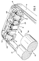
- figure 1, en vue éclatée, le dispositif d'alimentation selon l'invention installé dans un appareil mobile et accompagné de deux types de piles ;
- figure 2, le premier type de plots de contact, dits « de batterie », utilisé pour identifier les batteries rechargeables ;
- figure 3, le deuxième type de plots de contact, dits « mixtes », utilisés à la fois pour les piles et la batterie rechargeable ;
- figure 4, le troisième type de plots de contact, dit « double », utilisé pour les piles ;
- figure 5, le quatrième type de plots de contact, dit également « double », utilisé pour les piles ; et
- la figure 6, le montage de piles avec le dispositif d'alimentation selon l'invention.
- Figure 1, in exploded view, the power supply device according to the invention installed in a mobile device and accompanied by two types of batteries;
- Figure 2, the first type of contact pads, called "battery", used to identify rechargeable batteries;
- Figure 3, the second type of contact pads, called "mixed", used for both batteries and the rechargeable battery;
- Figure 4, the third type of contact pads, said "double", used for batteries;
- Figure 5, the fourth type of contact pads, also called "double", used for batteries; and
- Figure 6, the mounting of batteries with the power supply device according to the invention.
En se reportant d'abord à la figure 1, il est facile de se rendre compte du type de matériel auquel se rapporte l'invention. En effet, on distingue sur cette figure 1 un couvercle 1 devant venir se fixer sur un boîtier d'appareil 2, au moyen de deux tenons 5, après que soit installé, dans une cavité 3 du boîtier d'appareil 2, soit un jeu de trois piles primaires 10, soit une batterie rechargeable 20. La vue de type éclatée permet de distinguer les principaux éléments de l'appareil mobile du dispositif selon l'invention et les piles ou batterie utilisées.Referring first to Figure 1, it is easy to realize the type of equipment to which the invention relates. In fact, in this FIG. 1, a cover 1 can be seen which has to be fixed on an
On peut distinguer deux séries de plots de contact, l'une repérée 6, que l'on nommera « série de pieds », et 7, que l'on nommera « série de tête ». Chacune de ces séries 6 et 7 est placée de part et d'autre de la cavité 3, dans un ensemble d'encoches 4 moulées dans le boîtier d'appareil 2. L'agencement de chacune de ces deux séries 6 et 7, et notamment la forme des différents plots de contact qui les constituent, font qu'elles permettent d'accueillir, soit le jeu de trois piles primaires 10 de type standard, notamment du type référencé " R6 " par les normes, soit d'une batterie rechargeable 20 dont la forme doit être compatible avec la forme des différents plots de contact et leur positionnement.We can distinguish two series of contact pads, one marked 6, which will be called "series of feet", and 7, which will be called "series of head". Each of these series 6 and 7 is placed on either side of the cavity 3, in a set of
La forme de chacun des plots est représentée par une des figures 2 à 5.The shape of each of the studs is represented by one of FIGS. 2 to 5.
La figure 2 représente un premier type de plots de contact, dit de batterie, à savoir les plots de contact repérés 21 et 22 sur la figure 1. L'un d'entre eux est destiné à identifier le type batterie rechargeable placée dans la cavité 3, au moyen d'un circuit d'identification de la résistance électrique de ladite batterie rechargeable, situé dans le circuit imprimé. Il est ainsi possible de reconnaître différents types de batteries rechargeables, notamment celles équipées d'un composant « NTC » satisfaisant aux normes américaines. L'autre sert de connexion entre le plot de charge de la batterie rechargeable et le circuit de charge situé sur le circuit imprimé, qui est lui-même relié au chargeur, lorsque celui-ci est branché. Lorsqu'ils sont montés sur le boîtier d'appareil 2, ces plots de contact de batterie sont mis en connexion électrique avec la carte de circuits imprimés de l'appareil comportant un circuit d'identification de résistance électrique.FIG. 2 represents a first type of contact pad, called a battery, namely the contact pads marked 21 and 22 in FIG. 1. One of them is intended to identify the type of rechargeable battery placed in the cavity 3, by means of an identification circuit of the electrical resistance of said rechargeable battery, located in the printed circuit. It is thus possible to recognize different types of rechargeable batteries, in particular those equipped with an “NTC” component meeting American standards. The other serves as a connection between the charging pad of the rechargeable battery and the charging circuit located on the printed circuit, which is itself connected to the charger, when the latter is connected. When mounted on the
En référence à la figure 1, on constate que ces deux plots de contact de batterie 21 et 22 sont placés chacun entre deux plots de contact, respectivement, 11 et 31, 14 et 32. Toutefois, on notera que la position de leur lame de contact est légèrement moins proéminente que celle des deux contacts entre lesquels ils sont placés.Referring to Figure 1, we see that these two
La figure 2 permet de mieux distinguer la forme des plots de contact de batterie 21 ou 22, et en particulier la forme de la lame de contact 23, qui est droite, légèrement inclinée par rapport à une partie centrale 24 et dont l'extrémité est légèrement recourbée. La fixation de ces plots de contact de batterie 21, 22 se fait au moyen d'une patte inférieure 25 dont l'extrémité recourbée permet d'accrocher une paroi de l'ensemble d'encoches, référencé 4 sur la figure 1. Le positionnement exact de ces deux plots de contact de batterie 21 et 22 se fait grâce à deux parties latérales 26 venant épouser un bossage 27 de l'ensemble d'encoches 4. Ainsi, ces plots de contact de batterie 21 et 22 peuvent être fixés et détachés facilement de leur emplacement.FIG. 2 makes it possible to better distinguish the shape of the
En référence à la figure 3, on décrit un deuxième type de plots de contact, dit plots de contact mixtes, référencés 31 et 32 sur la figure 1. Ils sont positionnés sur le boîtier d'appareil 2, chacun à une extrémité d'une des deux séries de contact 6 et 7, de manière opposée et à côté d'un plot de contact de batterie 21 ou 22.With reference to FIG. 3, a second type of contact pads, known as mixed contact pads, referenced 31 and 32 in FIG. 1, are described. They are positioned on the
La figure 3 montre que leur lame de contact 33 est de forme bombée et se termine en col de cygne vers la partie qui la relie à une partie centrale 34 de ce plot de contact mixte. On note que cette lame de contact 33 a une largeur qui s'amincie au fur et à mesure que l'on s'approche de l'extrémité 37, mais que cette dernière est plus large. La position de tels plots mixtes se fait au moyen de deux parties latérales 36 recourbées pour épouser un bossage placé à une extrémité de chacun des ensembles d'encoches 4 et diamétralement opposé. Ces deux plots de contact mixtes 31 et 32 sont donc destinés à établir le contact entre les circuits de l'appareil mobile et aussi bien les piles primaires qu'une batterie rechargeable, mais ils constituent également les pôles positif et négatif du dispositif.Figure 3 shows that their
Ces deux premiers types de plots de contact sont donc utilisés pour alimenter électriquement l'appareil, lorsqu'une batterie rechargeable est utilisée.These first two types of contact pads are therefore used to power the device electrically, when a rechargeable battery is used.
Les contacts électriques pour un jeu de piles primaires, tels que celles utilisées dans le commerce, sont les plots de contact mixtes, déjà décrits en référence à la figure 3 et référencés 31 et 32 sur la figure 1, mais aussi les plots de contact double pour piles, 11, 12 et 13, 14 de la figure 1.The electrical contacts for a set of primary batteries, such as those used commercially, are the mixed contact pads, already described with reference to FIG. 3 and referenced 31 and 32 in FIG. 1, but also the double contact pads for batteries, 11, 12 and 13, 14 of figure 1.
La figure 4 représente un premier de ces deux types de plots de contact double. Le premier contact 11 de ces plots de contact double est destiné à être inséré dans une fente de l'ensemble d'encoches 4 de la série de contacts de pieds 6 (figure 1). Il comprend principalement un fond 46 limité par deux rebords 48 proéminents. Comme le montre la figure 6, les arêtes aux sommets de ces deux rebords 48 doivent servir de contact à l'extrémité plane 72 d'une pile 10, qui doit être insérée entre deux autres piles 10 identiques.FIG. 4 represents a first of these two types of double contact pads. The first contact 11 of these double contact pads is intended to be inserted into a slot in the set of
Cette première partie de contact 11 du plot de contact mobile est rattachée à une partie centrale 44 à laquelle est également fixée une deuxième partie de contact 12. Sa lame 43 est du type de celle décrite à la figure 3, référencée 33, et affecte une forme en col de cygne. Ses fonctions sont exactement les mêmes que celles de la lame 33 du plot de contact mixte 31 ou 32.This first contact part 11 of the movable contact pad is attached to a
Les extrémités 37 et 47 des lames 33 et 43 des deux types de plots de contact décrits par les figures 3 et 4 sont élargies pour pouvoir être bloquées par une partie fixe. La figure 6 permet de constater qu'une telle extrémité 47 d'une lame 43 est en appui dans une petite cavité d'un ensemble d'encoches 4, entre les rebords 9.The ends 37 and 47 of the
Ainsi, les lames 33 et 43 des plots de contact 12 et 31 sont maintenues en état de précontrainte, en une position déterminée en retrait par rapport à la profondeur de l'encoche dans laquelle chacune se trouve, pour éviter un contact avec l'extrémité plate d'une pile primaire et participer ainsi au détrompage. Enfin, cette précontrainte est nécessaire, car sans elle, il est difficile d'assurer que les lames 43 et 33 seront en retrait par rapport aux rebords 9, parce que les traitements thermiques infligés à ces lames (trempe 810°C et revenu 300°C) les déforment énormément.Thus, the
En fait, l'extrémité 37 du plot de contact mixte, référencé 32 sur la figure 1, n'est pas bloquée dans le boîtier d'appareil 2 et n'est donc pas opérationnelle. Son existence permet d'obtenir l'unicité du type de plot de contact mixte pour abaisser le coût de production par l'utilisation d'un seul outil de découpe et de pliage.In fact, the
La figure 5 montre le deuxième type de plot de contact double. On y retrouve une partie centrale 54 à laquelle sont reliés deux parties de contact 13 et 14 dont les lames 53 sont identiques à celle des plots de contact mixtes 31 ou 32 et à celle de la deuxième partie de contact 12 du double plot de contact, décrit à la figure 4. Leurs fonctions sont également identiques à ces lames 33 et 43, précédemment décrites.FIG. 5 shows the second type of double contact pad. There is a
On précise que les plots de contact doubles des figures 4 et 5 ne sont pas en contact avec le circuit imprimé et ne servent que pour les piles primaires. En effet, ils servent à faire la liaison entre les piles primaires placées sur les côtés du boîtier et la pile primaire se trouvant au milieu, mais aussi pour le détrompage du montage de ces piles primaires.It is specified that the double contact pads of FIGS. 4 and 5 are not in contact with the printed circuit and are used only for the primary batteries. Indeed, they are used to make the connection between the primary batteries placed on the sides of the case and the primary battery being in the middle, but also for the coding of the assembly of these primary batteries.
On remarquera que sur ces quatre réalisations décrites par les figures 2 à 5, chacun des plots de contact possède une languette 29, 39, 49, 59 obtenue par enfoncement partiel du métal constituant ces plots de contact. L'ouverture de la languette 29, 39, 49, 59 se fait vers le haut, de sorte que chacune d'elle constitue un système de blocage du plot de contact dans sa position, et qu'il est difficile d'enlever ce dernier de son emplacement, sans agir directement sur chacune de ces languettes 29, 39, 49 ou 59.Note that in these four embodiments described in Figures 2 to 5, each of the contact pads has a
La figure 6 permet de mieux comprendre comment ces différents plots de contact sont installés et fixés dans le boîtier de l'appareil 2, et plus exactement dans un ensemble d'encoches 4.FIG. 6 provides a better understanding of how these different contact pads are installed and fixed in the housing of the
Il est bon de noter que les piles primaires 10 devant être acceptées par ce boîtier sont fabriquées par différentes compagnies de pays différents et, de ce fait, leur longueur peut varier légèrement. Les lames et plots de contact qui les accueillent doivent donc faire preuve d'une certaine flexibilité pour accepter une petite différence de longueur, tout en assurant le contact électrique et le maintien en place des piles.It is good to note that the
Le plot de contact 12 a sa lame 43 en forme de col de cygne placée entre deux rebords 9 de l'ensemble d'encoches 4, et ne dépasse pas de la cavité définie par ces deux rebords 9. De plus, l'écartement de ces deux rebords 9 de l'ensemble d'encoches 4 est supérieur à un plot de contact 71 de la pile 10, mais inférieur au diamètre de cette même pile 10. Toutefois, il est possible, pour l'utilisateur, de placer la pile dans le sens inverse à celui représenté sur la figure 6, mais le système de détrompage est le suivant. Si cette pile est placée dans le sens inverse, il n'y aura pas contact entre son extrémité plane 72 et la lame 33 du plot de contact, car elle touchera avant le rebord 9. C'est pour cela que la lame 33 du plot de contact en question est précontrainte et se trouve donc en retrait par rapport aux rebords 9. Cette remarque est également valable pour le détrompage de la pile placée au milieu. L'opérateur peut introduire la pile 10 par son plot de contact rond, mais il n'y aura pas contact entre celui-ci et le plot de contact 11 de la figure 1, donc l'appareil ne fonctionnera pas et l'opérateur vérifiera le sens d'introduction des piles, par ailleurs expliqué, grâce à un schéma directement dessiné dans le plastique du boîtier 2. Ceci constitue les premiers moyens de détrompage.The
En ce qui concerne la pile 10 placée au milieu, son montage doit s'effectuer en sens inverse. De ce fait, le contact électrique sera assuré par l'arête des rebords 48 du double plot de contact. Une butée 8 moulée dans l'ensemble d'encoches 4 constitue des deuxièmes moyens de détrompage et permet également à l'opérateur de ne pas pouvoir y introduire la pile 10 par son plot de contact rond, mais par son extrémité plane sans plot 72. Ceci constitue les deuxièmes moyens de détrompage.With regard to the
Il existe des piles secondaires de la batterie rechargeable qui n'ont pas le même diamètre que celui des piles de type R6. Dans ce cas, un élément espaceur, par exemple en plastique thermoformé, peut être utilisé.There are secondary batteries in the rechargeable battery which do not have the same diameter as that of the R6 type batteries. In this case, a spacer, for example in thermoformed plastic, can be used.
La figure 1 permet de constater, sur la batterie rechargeable 20, l'existence de plaques de contact 60, de même que des fentes de positionnement 61 placées en correspondance, les plots de contact mixtes 31 et 32 se trouvent en correspondance de ces fentes, lorsque la batterie rechargeable est mise en place. Il y a impossibilité pour l'utilisateur de procéder à un montage ne correspondant pas à celui réclamé par le fonctionnement de l'appareil. De plus, les plaques de contact 60 permettent d'établir le contact électrique entre les plots de contact de batterie 21 et 22, mais aussi avec les plots de contact mixtes 31 et 32, positif et négatif.FIG. 1 shows, on the
La batterie rechargeable est conçue à des dimensions exactes définies par la cavité 3 du boîtier d'appareil 2 et la position des deux ensembles d'encoches 4. Elle utilise des contacts soudés pour connecter entre eux les différents éléments de piles secondaires les constituant. De plus, dans le but de protéger les batteries rechargeables, chacune d'entre elles possède un interrupteur thermique (thermo-switch), tout comme le composant à coefficient de température négatif NTC. Ceci permet d'éviter des problèmes de surcharge lors des opérations de chargement.The rechargeable battery is designed to exact dimensions defined by the cavity 3 of the
Pour éviter la destruction de l'appareil mobile, en particulier d'un téléphone portatif, on utilise également une diode placée entre le plot de contact mixte 31, positif, pour les piles primaires et le pôle positif de l'appareil portatif. On fait remarquer qu'un même plot de contact mixte 31 positif est utilisé à la fois pour les piles et pour les batteries rechargeables. En correspondance, le plot de contact mixte 32, diamétralement opposé au plot de contact mixte 31 est le seul plot de contact utilisé pour la mise à la terre.To avoid the destruction of the mobile device, in particular of a portable telephone, a diode is also used placed between the
On peut obtenir une grande élasticité en faisant subir aux lames 23, 33, 43, 53, de différents plots de contact, un traitement thermique, comme une trempe à 810°C et un revenu à 300°C pour l'acier XC 75 recouvert de cuivre ou de nickel. Un recouvrement de cuivre permet d'obtenir une très bonne liaison avec le nickel et un revêtement de nickel permet d'obtenir une très bonne résistance de contact entre le métal et les piles primaires et les batteries rechargeables dont les extrémités sont également faites de nickel.A high elasticity can be obtained by subjecting the
Le dispositif d'alimentation, selon l'invention, évite l'emploi d'une pièce amovible tout en permettant l'utilisation, à la fois de batteries rechargeables et de piles primaires.The power supply device according to the invention avoids the use of a removable part while allowing the use of both rechargeable batteries and primary batteries.
Il accepte tous les standard de piles primaires de normes " R6 ".It accepts all primary battery standard "R6" standards.
Il évite le chargement excessif des batteries rechargeables.It prevents excessive charging of rechargeable batteries.
Il permet de reconnaître le type de batteries rechargeables utilisé.It allows to recognize the type of rechargeable batteries used.
Enfin, les moyens de détrompage empêchent l'utilisateur d'effectuer un montage incorrect des piles primaires.Finally, the polarizing means prevent the user from incorrectly mounting the primary batteries.
Claims (8)
Applications Claiming Priority (2)
| Application Number | Priority Date | Filing Date | Title |
|---|---|---|---|
| FR0007863 | 2000-06-20 | ||
| FR0007863 | 2000-06-20 |
Publications (2)
| Publication Number | Publication Date |
|---|---|
| EP1168467A1 true EP1168467A1 (en) | 2002-01-02 |
| EP1168467B1 EP1168467B1 (en) | 2011-10-12 |
Family
ID=8851448
Family Applications (1)
| Application Number | Title | Priority Date | Filing Date |
|---|---|---|---|
| EP01202255A Expired - Lifetime EP1168467B1 (en) | 2000-06-20 | 2001-06-12 | Power supply device of a portable apparatus capable to use different supply types |
Country Status (5)
| Country | Link |
|---|---|
| US (1) | US6600291B2 (en) |
| EP (1) | EP1168467B1 (en) |
| JP (1) | JP2002050331A (en) |
| KR (1) | KR100807412B1 (en) |
| CN (1) | CN1208853C (en) |
Cited By (2)
| Publication number | Priority date | Publication date | Assignee | Title |
|---|---|---|---|---|
| EP1347531A2 (en) * | 2002-03-20 | 2003-09-24 | Nec Tokin Corporation | Battery pack |
| CN103668919A (en) * | 2013-11-28 | 2014-03-26 | 谢虹 | Mini-sized electric iron |
Families Citing this family (16)
| Publication number | Priority date | Publication date | Assignee | Title |
|---|---|---|---|---|
| FR2858123B1 (en) * | 2003-07-23 | 2006-02-10 | Euro Prot Surveillance | CONNECTING TERMINAL FORMING REMOTE CONTROLLER |
| JP4595655B2 (en) * | 2005-04-28 | 2010-12-08 | 株式会社デンソー | Electronic circuit device and manufacturing method thereof |
| CN101079508B (en) * | 2006-05-26 | 2010-05-12 | 朱治民 | Charger |
| CN101267614B (en) * | 2007-03-16 | 2011-02-02 | 夏新科技有限公司 | A power supply method and system for mobile phone |
| EP2171778A1 (en) * | 2007-06-26 | 2010-04-07 | The Coleman Company, Inc. | Electrical appliance that utilizes multiple power sources |
| US7897276B2 (en) | 2007-07-30 | 2011-03-01 | Hewlett-Packard Development Company, L.P. | Intersecting battery cavities |
| US8298696B1 (en) | 2008-06-03 | 2012-10-30 | Eddie Dana | Battery systems and methods thereof |
| JP5496489B2 (en) * | 2008-11-06 | 2014-05-21 | 三洋電機株式会社 | Two types of battery pack chargers |
| US8259221B1 (en) * | 2009-04-15 | 2012-09-04 | Cisco Technology, Inc. | System and method for charging rechargeable batteries in a digital camera |
| US9912175B2 (en) * | 2010-04-23 | 2018-03-06 | 9609385 Canada Inc. | Battery harvester |
| BR112013018674A8 (en) * | 2011-01-25 | 2018-02-06 | Koninklijke Philips Nv | BATTERY ADAPTER AND METHOD OF MANUFACTURING A BATTERY ADAPTER |
| FR2975750A1 (en) | 2011-05-26 | 2012-11-30 | Zedel | DEVICE FOR ELECTRICALLY SUPPLYING A PORTABLE LAMP |
| US9450431B2 (en) * | 2012-12-24 | 2016-09-20 | Leapfrog Enterprises, Inc. | Rechargeable battery |
| US20160372723A1 (en) * | 2015-05-19 | 2016-12-22 | MOHOC, Inc. | Battery bays and systems configured for different battery types |
| JP6888045B2 (en) * | 2019-04-22 | 2021-06-16 | 本田技研工業株式会社 | Battery pack |
| EP3981036A1 (en) * | 2019-06-10 | 2022-04-13 | 3M Innovative Properties Company | Adapter for battery compartment |
Citations (6)
| Publication number | Priority date | Publication date | Assignee | Title |
|---|---|---|---|---|
| US3856577A (en) * | 1971-07-22 | 1974-12-24 | Suwa Seikosha Kk | Electrochemical cell support and contact structure |
| US5015546A (en) * | 1989-06-12 | 1991-05-14 | Grid Systems Corporation | Battery compartment |
| EP0493253A1 (en) * | 1990-12-27 | 1992-07-01 | Lg Electronics Inc. | Socket for batteries |
| US5661392A (en) * | 1995-09-26 | 1997-08-26 | General Research Of Electronics, Inc. | Device for causing electronic apparatus to use a selectively mounted non-rechargeable battery pack or rechargeable battery pack |
| WO1997045900A1 (en) * | 1996-05-31 | 1997-12-04 | The Whitaker Corporation | Rechargeable battery connector |
| US6014009A (en) * | 1997-04-25 | 2000-01-11 | Data General Corporation | Electronic device |
Family Cites Families (8)
| Publication number | Priority date | Publication date | Assignee | Title |
|---|---|---|---|---|
| JPS6356560U (en) * | 1986-09-30 | 1988-04-15 | ||
| JPH1050283A (en) * | 1996-07-31 | 1998-02-20 | Nec Shizuoka Ltd | Battery terminal receiving part of battery housing part |
| FR2759523B1 (en) | 1997-02-10 | 1999-03-19 | Alsthom Cge Alcatel | POWER SUPPLY OF A PORTABLE DEVICE, OF THE TYPE ALLOWING THE USE OF DIFFERENT TYPES OF POWER SUPPLY, AND CORRESPONDING PORTABLE DEVICE |
| JPH11176404A (en) * | 1997-12-08 | 1999-07-02 | Sony Corp | Secondary battery and battery housing device |
| KR100415989B1 (en) * | 1998-07-11 | 2004-05-20 | 삼성전자주식회사 | A portable computer usable a computer-specific battery pack or ordinary battery |
| US6172480B1 (en) * | 1998-10-23 | 2001-01-09 | Primetech Electronics, Inc. | Compact fast battery charger |
| JP2000149896A (en) * | 1998-11-06 | 2000-05-30 | Nec Mobile Commun Ltd | Different-kind dry cell storing case |
| JP2005535074A (en) * | 2002-07-31 | 2005-11-17 | ラヨヴァック・コーポレーション | Method and apparatus for detecting presence / absence of secondary battery |
-
2001
- 2001-06-12 EP EP01202255A patent/EP1168467B1/en not_active Expired - Lifetime
- 2001-06-16 CN CNB011254351A patent/CN1208853C/en not_active Expired - Fee Related
- 2001-06-18 KR KR1020010034247A patent/KR100807412B1/en not_active IP Right Cessation
- 2001-06-18 JP JP2001183625A patent/JP2002050331A/en active Pending
- 2001-06-20 US US09/885,706 patent/US6600291B2/en not_active Expired - Lifetime
Patent Citations (6)
| Publication number | Priority date | Publication date | Assignee | Title |
|---|---|---|---|---|
| US3856577A (en) * | 1971-07-22 | 1974-12-24 | Suwa Seikosha Kk | Electrochemical cell support and contact structure |
| US5015546A (en) * | 1989-06-12 | 1991-05-14 | Grid Systems Corporation | Battery compartment |
| EP0493253A1 (en) * | 1990-12-27 | 1992-07-01 | Lg Electronics Inc. | Socket for batteries |
| US5661392A (en) * | 1995-09-26 | 1997-08-26 | General Research Of Electronics, Inc. | Device for causing electronic apparatus to use a selectively mounted non-rechargeable battery pack or rechargeable battery pack |
| WO1997045900A1 (en) * | 1996-05-31 | 1997-12-04 | The Whitaker Corporation | Rechargeable battery connector |
| US6014009A (en) * | 1997-04-25 | 2000-01-11 | Data General Corporation | Electronic device |
Cited By (4)
| Publication number | Priority date | Publication date | Assignee | Title |
|---|---|---|---|---|
| EP1347531A2 (en) * | 2002-03-20 | 2003-09-24 | Nec Tokin Corporation | Battery pack |
| EP1347531A3 (en) * | 2002-03-20 | 2004-08-25 | Nec Tokin Corporation | Battery pack |
| US7183014B2 (en) | 2002-03-20 | 2007-02-27 | Nec Tokin Corporation | Battery pack |
| CN103668919A (en) * | 2013-11-28 | 2014-03-26 | 谢虹 | Mini-sized electric iron |
Also Published As
| Publication number | Publication date |
|---|---|
| KR100807412B1 (en) | 2008-02-25 |
| CN1333572A (en) | 2002-01-30 |
| CN1208853C (en) | 2005-06-29 |
| KR20020000111A (en) | 2002-01-04 |
| JP2002050331A (en) | 2002-02-15 |
| US20020060550A1 (en) | 2002-05-23 |
| EP1168467B1 (en) | 2011-10-12 |
| US6600291B2 (en) | 2003-07-29 |
Similar Documents
| Publication | Publication Date | Title |
|---|---|---|
| EP1168467B1 (en) | Power supply device of a portable apparatus capable to use different supply types | |
| JP5044055B2 (en) | Power pack charging system and power tool charging system | |
| EP0674287A1 (en) | Casing for IC-card reader | |
| FR2550014A1 (en) | ELECTRIC BATTERY MOUNT, FOR FLAT BATTERIES | |
| JP5805705B2 (en) | Multiple battery polarity protection | |
| FR2661296A3 (en) | PORTABLE RADIOTELEPHONE POWERED BY BATTERY. | |
| WO2007071878A2 (en) | Case for recharging an electronic apparatus in a mobility situation | |
| FR2884354A3 (en) | HOUSING STRUCTURE FOR LAPTOP BATTERY | |
| EP0675456B1 (en) | Casing for IC-card reader | |
| US6807067B2 (en) | Battery-Locking mechanism | |
| EP0858172B1 (en) | Portable apparatus, and power pack for the portable apparatus capable of using different types of battery types | |
| EP1978608A1 (en) | Electrical charger in several parts | |
| WO2010125259A1 (en) | Device for recharging a portable electronic apparatus | |
| FR2806836A1 (en) | Battery adapter for D size battery, has upper housing with clearance opening in tube which extends from peripheral edge lying opposite flange, for accommodating positive pole | |
| FR2988068A1 (en) | AUTOMATIC CYCLE STORAGE SYSTEM, CYCLE FOR SUCH A SYSTEM AND USE OF A BATTERY FOR SUCH A CYCLE. | |
| CA2948387C (en) | Cutaneous device, in particular a pulse generator for electrical stimulation | |
| EP1834366B1 (en) | Battery powered device for an power meter and the power meter | |
| EP1825278B1 (en) | Electric connection device for a polyphase electric meter | |
| FR2578103A1 (en) | Battery box, in particular for military use | |
| FR3132225A1 (en) | Rechargeable electronic cap and charging base | |
| FR3023150A1 (en) | RANGE ACCESSORY DEVICE FOR AC ADAPTER AND ELECTRICAL CORD WITH AT LEAST ONE CONNECTOR | |
| FR3136604A3 (en) | Grounding adapter | |
| GB2351179A (en) | Rechargeable battery | |
| WO2015193124A1 (en) | Structure for producing and storing electrical energy | |
| JPH07335270A (en) | Charger device |
Legal Events
| Date | Code | Title | Description |
|---|---|---|---|
| PUAI | Public reference made under article 153(3) epc to a published international application that has entered the european phase |
Free format text: ORIGINAL CODE: 0009012 |
|
| AK | Designated contracting states |
Kind code of ref document: A1 Designated state(s): DE FR GB Kind code of ref document: A1 Designated state(s): AT BE CH CY DE DK ES FI FR GB GR IE IT LI LU MC NL PT SE TR |
|
| AX | Request for extension of the european patent |
Free format text: AL;LT;LV;MK;RO;SI |
|
| 17P | Request for examination filed |
Effective date: 20020702 |
|
| AKX | Designation fees paid |
Free format text: DE FR GB |
|
| RAP1 | Party data changed (applicant data changed or rights of an application transferred) |
Owner name: NXP B.V. |
|
| 17Q | First examination report despatched |
Effective date: 20091214 |
|
| GRAP | Despatch of communication of intention to grant a patent |
Free format text: ORIGINAL CODE: EPIDOSNIGR1 |
|
| GRAS | Grant fee paid |
Free format text: ORIGINAL CODE: EPIDOSNIGR3 |
|
| GRAA | (expected) grant |
Free format text: ORIGINAL CODE: 0009210 |
|
| AK | Designated contracting states |
Kind code of ref document: B1 Designated state(s): DE FR GB |
|
| REG | Reference to a national code |
Ref country code: GB Ref legal event code: FG4D Free format text: NOT ENGLISH |
|
| REG | Reference to a national code |
Ref country code: DE Ref legal event code: R081 Ref document number: 60145486 Country of ref document: DE Owner name: OCT CIRCUIT TECHNOLOGIES INTERNATIONAL LTD., IE Free format text: FORMER OWNER: KONINKLIJKE PHILIPS ELECTRONICS N.V., EINDHOVEN, NL |
|
| REG | Reference to a national code |
Ref country code: DE Ref legal event code: R096 Ref document number: 60145486 Country of ref document: DE Effective date: 20111215 |
|
| RAP2 | Party data changed (patent owner data changed or rights of a patent transferred) |
Owner name: ST-ERICSSON SA |
|
| PLBE | No opposition filed within time limit |
Free format text: ORIGINAL CODE: 0009261 |
|
| STAA | Information on the status of an ep patent application or granted ep patent |
Free format text: STATUS: NO OPPOSITION FILED WITHIN TIME LIMIT |
|
| 26N | No opposition filed |
Effective date: 20120713 |
|
| REG | Reference to a national code |
Ref country code: DE Ref legal event code: R097 Ref document number: 60145486 Country of ref document: DE Effective date: 20120713 |
|
| REG | Reference to a national code |
Ref country code: FR Ref legal event code: PLFP Year of fee payment: 16 |
|
| REG | Reference to a national code |
Ref country code: DE Ref legal event code: R082 Ref document number: 60145486 Country of ref document: DE Representative=s name: GRUENECKER PATENT- UND RECHTSANWAELTE PARTG MB, DE Ref country code: DE Ref legal event code: R081 Ref document number: 60145486 Country of ref document: DE Owner name: OCT CIRCUIT TECHNOLOGIES INTERNATIONAL LTD., IE Free format text: FORMER OWNER: NXP B.V., EINDHOVEN, NL |
|
| REG | Reference to a national code |
Ref country code: FR Ref legal event code: PLFP Year of fee payment: 17 |
|
| PGFP | Annual fee paid to national office [announced via postgrant information from national office to epo] |
Ref country code: DE Payment date: 20170522 Year of fee payment: 17 Ref country code: FR Payment date: 20170523 Year of fee payment: 17 Ref country code: GB Payment date: 20170526 Year of fee payment: 17 |
|
| REG | Reference to a national code |
Ref country code: FR Ref legal event code: TP Owner name: OCT CIRCUIT TECHNOLOGIES INTERNATIONAL LIMITED, IE Effective date: 20180116 |
|
| REG | Reference to a national code |
Ref country code: DE Ref legal event code: R119 Ref document number: 60145486 Country of ref document: DE |
|
| GBPC | Gb: european patent ceased through non-payment of renewal fee |
Effective date: 20180612 |
|
| PG25 | Lapsed in a contracting state [announced via postgrant information from national office to epo] |
Ref country code: FR Free format text: LAPSE BECAUSE OF NON-PAYMENT OF DUE FEES Effective date: 20180630 Ref country code: DE Free format text: LAPSE BECAUSE OF NON-PAYMENT OF DUE FEES Effective date: 20190101 Ref country code: GB Free format text: LAPSE BECAUSE OF NON-PAYMENT OF DUE FEES Effective date: 20180612 |