EP0197761A2 - Fundus camera - Google Patents
Fundus camera Download PDFInfo
- Publication number
- EP0197761A2 EP0197761A2 EP86302446A EP86302446A EP0197761A2 EP 0197761 A2 EP0197761 A2 EP 0197761A2 EP 86302446 A EP86302446 A EP 86302446A EP 86302446 A EP86302446 A EP 86302446A EP 0197761 A2 EP0197761 A2 EP 0197761A2
- Authority
- EP
- European Patent Office
- Prior art keywords
- transmission
- receiving
- object plane
- image
- slit
- Prior art date
- Legal status (The legal status is an assumption and is not a legal conclusion. Google has not performed a legal analysis and makes no representation as to the accuracy of the status listed.)
- Withdrawn
Links
Images


Classifications
-
- A—HUMAN NECESSITIES
- A61—MEDICAL OR VETERINARY SCIENCE; HYGIENE
- A61B—DIAGNOSIS; SURGERY; IDENTIFICATION
- A61B3/00—Apparatus for testing the eyes; Instruments for examining the eyes
- A61B3/10—Objective types, i.e. instruments for examining the eyes independent of the patients' perceptions or reactions
- A61B3/14—Arrangements specially adapted for eye photography
Definitions
- the present invention relates generally to optical imaging systems and more particularly to an optical imaging system for forming an image of an object plane within a sample medium.
- optical imaging systems form an image of the surface of an object.
- the sample medium is a human organ, such as, for example, the human eye.
- the object plane may be selected to lie in the cornea or along the retina. High-quality images of the retina are vital to diagnosing a large variety of medical conditions.
- the process of forming an optical image of an object plane includes the steps of illuminating the object plane, collecting the reflected light emanating from the object plane, and focusing the collected light on an image plane.
- these optical systems include lenses and mirrors to accomplish the various functions of illuminating, collecting, and focusing.
- Forming a high-quality image of an object plane within a sample medium requires special techniques to overcome the deterioration of the image due to scattering of the illuminating light from the region of the sample medium external to the object plane. This scattered light is collected and focused along with light emanating from the object plane and thus obfuscates the image formed of the object plane.
- Existing systems for imaging an object plane within a sample medium generally include an illuminating slit, for illuminating a region of the object plane, a viewing slit, for viewing the illuminated region of the object plane, and optics configured so that the region of the sample medium external to the object plane is not viewable through the viewing slit. Accordingly, most of the light scattered by the external sample medium will not pass through the viewing slit. Only the light passing through the viewing slit is focused on the image plane, thus, the obfuscation of the image of the object plane by this scattered light is substantially obviated.
- the above-described systems only provide an image of a narrow, slit-shaped region of the object plane at a given time. To view a significant region of the object plane the slit is scanned across the object plane.
- Two examples of the above-described system are disclosed in U.S. Patent Nos. 3,547,512 and 4,170,398 issued to Baer and Koester, respectively.
- the illuminating slit and viewing slit are formed in planar diaphragms disposed substantially at right angles to each other.
- the scanning of the slits is accomplished by oscillating the diaphragms about an axis.
- the illuminating and viewing slits are formed in planar diaphragms disposed substantially parallel to each other.
- the scanning of the slit is accomplished by a system utilizing a rotating mirror.
- the above-described systems provide a high-quality image of an object plane in a sample medium such as, for example, the retina of the human eye.
- a sample medium such as, for example, the retina of the human eye.
- these devices do not provide for selectable alternate functions such as illuminating and viewing through colored filters to perform chemical analysis, non-coincident illumination and viewing, and stereo image formation. These functions are vitally important in many applications. Additionally, functions such as flare control, auto-focusing, and eye position error indication are highly desirable.
- the present invention is a unique system for forming an image of an object plane in a sample medium, such as for example, the retina of the human eye.
- transmission and receiving slits are formed in a cylindrical drum.
- the long edges of the slits are disposed along a common axis parallel to the axis of the cylindrical drum.
- the light passing through the transmission slit is guided along a transmission path formed by optical components including mirrors and lenses.
- the transmission path forms an image of the transmission slit on the object plane in the sample medium, where this image is denoted the illumination region.
- the slit plane i.e. the plane in which the transmission and receiving slits are located, and the object plane are conjugate planes.
- a portion of the light emanating from the illumination region is guided to the receiving slit by optical elements in the receiving path.
- the light passing through the transmission slit that is focused onto the illumination region by the transmission path is termed the illumination beam and the light that is directed through the receiving slit by the receiving path is termed the viewing beam.
- the illumination region is scanned across the object plane when the drum is rotated about its axis.
- the rate with which the illumination region scans the object plane is determined by the rate of rotation of the cylindrical drum. Scanning the illumination region across the object plane corresponds to the synchronous scanning of the illumination and viewing beams across the object plane.
- the cylindrical drum has several transmission/receiving slit pairs formed thereon.
- Active optical elements such as prisms, filters, lenses, or gratings, may be placed in a given slit pair so that slit performs a desired optical function.
- the receiving slit may be displaced along the drum to provide for non-coincident illumination and viewing of the object plane.
- a system for selecting a specific slit function is also part of the invention.
- Examples of slit function include full color photographic imagery, use of color filters for enhancing various retinal features, imagery using indirect illumination, and fluorescein angiography.
- a further aspect of the invention is a system for determining the horizontal, vertical, and axial displacement of the eye from its correct position relative to the imaging system.
- the transmission and receiving beams in the sample medium are optically displaced so that regions of the sample medium external to the object plane and illuminated by the illumination beam may not be viewed through the receiving slit, thereby preventing light scattered from the external sample medium from passing through the receiving slit and obfuscating the image of the object plane.
- the displacement of the transmission and receiving beams is accomplished by an aperture structure, including three apertures placed vertically with respect to the receiving path and a first receiving mirror positioned with its reflecting surface disposed to reflect light, emanating from the object plane and passing through the center aperture, along the receiving path; and with its non-reflective side disposed to block the illumination beam from passing through the center aperture of the aperture structure.
- This configuration results in a viewing beam positioned between two outer illumination beams where both illumination beams are focused on the illumination slit on the object plane.
- a light source for forming an input light beam incident on the transmission slit.
- This light source includes a flash lamp, a mirror for producing a flash lamp image, and a lamp lens for focusing the lamp and the lamp image on the first and second outer apertures of the aperture structure, respectively.
- an imaging path comprising mirrors and lenses directs the received light passing through said receiving slit (the output beam) to an image plane and focuses this light onto an image slit where the image slit is the optical image of said receiving slit, and where the slit plane and the image plane are conjugate planes.
- optical means are provided for directing the received light passing through said receiving beams to alternate imaging planes.
- an electronic imaging device for example a vidicon tube, may be utilized to receive this scanning imaging slit and produce an image of the object plane.
- the sweep of the vidicon tube is synchronized to the sweep of the imaging slit to thereby enhance the quality of the vidicon tube image and to provide for reception of successively scanned illumination slits having a short time interval therebetween.
- an autofocusing feature is included. Prisms are placed in the center aperture to deflect the image of the transmission slit and the position of wires, disposed in the receiving slit, relative to the deflected images is utilized to determine whether the system is in focus.
- the ability of the present system to provide multiple slit functions provides for hitherto unavailable optical images of the eye.
- Different color filters may be placed in the transmission and receiving slits to highlight retinal features. Illumination and viewing may be performed through displaced slits for imaging using indirect illumination. Additionally the present invention provides many other advantages not realized in the art.
- the present invention is a novel system for forming an image of an object plane disposed in a sample medium.
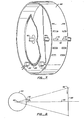
- Figure 1 is a highly stylized view, in perspective, of a section of the present invention.
- the sample medium is a human eye 10 with the object plane being the retina, or fundus, 12 of the eye.
- the interior of the eye 13 scatters the incoming light utilized to form an image of the retina 12.
- Incoming light transmitted through a transmission slit 14, termed the illumination beam is directed to an illumination region 16 on the retina 12 by a transmission path 17 comprising first and second transmission mirrors 18 and 20, a transmission aperture lens 22, a first and second outer apertures 24a and 24b of an aperture structure 26, and an eye lens 28.
- the receiving path comprises the eye lens 28, the center aperture 34 of the aperture structure 26, first and second receiving mirrors 36 and 38 and a receiving aperture lens 40.
- the first receiving mirror 36 is positioned . so that only light passing through the center aperture 34 is reflected into the receiving path 30. Thus, light emanating from the illumination region 16 that passes through the first and second outer apertures 24a and 24b is not directed through the receiving slit 32.
- the non-reflective surface of the first receiving mirror 36 prevents light in the illumination beam from passing through the center aperture 34. Thus, the transmission beam passes through only the first and second outer apertures 24a and 24b and not through the center aperture 34.
- Fig. 2 is a more detailed view of the human eye 10 showing the configuration of the illumination and viewing beams 35a and b.
- the optics of the system are designed to focus 24a', 24b' and 34' images of the outer and center apertures 24a, 24b, and 34 on the pupil of the eye 10.
- the illumination beam 35a is formed only from light passing through the outer aperture images 24a' and b' because the non- reflecting surface of the first receiving mirror 36 in Fig. 1 prevents passage of light through the center aperture 34 to the eye 10. This light is focused onto the illumination region 16 as described above.
- the transmission/receiving slit pair 42 is formed in a diaphragm in the shape of a cylindrical drum 44.
- the cylindrical drum 44 is depicted in greater detail in Fig. 7.
- the cylindrical drum has an axis of symmetry 46 about which the drum is rotated to scan the illumination slit across the retina 16.
- the drum includes a plurality of transmission/receiving slit pairs 42 displaced circumferentially around the drum 44.
- Eye lens 28 is selected so that the apertures 24a, 24b and 36 are focused on the pupil of the eye 10, and so that the plane of the pupil and the plane of the aperture structure 26 are conjugate planes.
- the system is configured so that the transmission slit 14 and receiving slit 32 are imaged at the illumination region 16 on the retina.
- a start configuration will now be described where the transmission/receiving slit pair 42, receiving mirrors 36 and 38, transmission mirrors 18 and 20, aperture lenses 22 and 40, eye lens 28, and drum axis 46 are all in the same plane designated the axis plane 45.
- a slit plane 48 is defined as the plane perpendicular to the axis plane 45 having the transmission/receiving slit pair 42 disposed thereon when in the start configuration, while the object plane 50 is the plane perpendicular to the axis plane having the illumination region 16 disposed thereon when in the start position. All points disposed on the slit plane 48 will be imaged on the object plane 50 by the optical system, thus, the slit plane 48 and object plane 50 are termed conjugate planes.
- the transmission/receiving slit pair 42 are displaced along the slit plane 48 while the illumination region 16 is displaced along the object plane 50.
- the object plane 50 can be scanned by the illumination region 16 if the drum 44 is rotated.
- the slit pair 42 is displaced from the slit plane 48 due to the circular shape of the drum 44.
- a good image of the slits 14 and 32 is maintained on the retina 12 within a critical angular displacement from the axis plane 45.
- the path length of the transmission and receiving beams 17 and 30 must be equal for the beams to scan the retina at the same rate.
- a unique Z configuration in the transmission path 17 formed by the placement of transmission mirrors 18 and 20 equalizes the path length of the transmission path and receiving path 17 and 30.
- Figure 3 is a side view taken perpendicularly to the axis plane 45 depicting a unique source configuration for providing input light to the illumination beam 35a.
- a flash lamp 50 and reflector 51 are disposed slightly below the axis plane 45.
- a source mirror 52 is utilized to create a source image 54 of the flash lamp 50 where the flash lamp 50 and the source image are symmetrically disposed about the axis plane 45 and are positioned in a source plane 55 disposed almost perpendicularly to the axis plane 45 (see Fig. 3).
- Source lens 56 is positioned between the transmission slit 14 and the source plane 55.
- the source lens 56 has its optical axis disposed in the start plane 45 and is configured so that images of the flash lamp 50 and the source image 54 are focused at the first and second outer apertures 24a and 24b, respectively, of the aperture structure 26. This configuration assures that most of the light generated from the flash lamp 50 passes through the first and second outer apertures along the transmission path 17. Note that as the drum 44 rotates, the first transmission slit 14a will eventually reach an angle after which light from the source will no longer pass through the transmission slit and through the first and second outer apertures 24a and 24b. This angle determines the outer limits of the angular sweep of the illumination slit along the retina of the eye.
- Fig. 3 also illustrates how the placement of the first receiving mirror 36 prevents light in the illumination beam from passing through the center aperture 34 of the aperture structure 26.
- the non-reflective side of the first receiving mirror 36 is positioned to block outgoing light from passing through the center aperture 34.
- Figure 4 is a schematic diagram of an imaging path utilized to direct light passing through the receiving slit 32 onto an image region 62 formed on an image plane 64.
- An imaging lens 60 forms an image of the receiving slit 32 on an image plane 64.
- the image plane 64 is conjugate to the slit plane 48 and, since the slit plane 48 is conjugate to the object plane 50, the image plane 64 and object plane 50 are also conjugate planes.
- the vertical displacement of the receiving slit 32 due to the rotation of the drum 44 causes the image region 62 to sweep across the image plane 64, thus forming an image of the region of the object plane 50 being swept by the illumination region 16.
- the light passing through the receiving slit 32 that is focussed onto image plane 64 by the image path is termed the output beam.
- Fig. 4 also illustrates how the receiving mirror 36 only directs incoming light passing through the center aperture 34 of the aperture structure 26 into the receiving beam 30. Note that incoming light passes through all the apertures 24a, 24b, and 34, however, the receiving mirror 36 is positioned so that only incoming light passing through the center aperture 34 is deflected into the receiving path 30.
- Any suitable medium for storing the image of the retina formed on the image plane 64 may be utilized.
- photographic film may be placed at the image plane 64 and the sweep of the imaging slit 62 across the planar surface of the film is analogous to the sweep of a focal plane shutter across the film.
- a vidicon tube includes a light receiving surface which is swept by an electron beam. This sweeping of the electron beam is accomplished by sequential horizontal sweeps of the beam where the beam is stepped vertically at the completion of each horizontal sweep.
- the electron beam is part of a circuit that includes the light receiving surface of the vidicon tube, where the conductivity of the vidicon tube is determined by the magnitude of light intensity at the point of impact of the electron beam on the light receiving surface.
- the intensity of the light at a given point is measured by the amount of electron current generated when the electron beam is incident at that point.
- the light receiving surface of the vidicon tube is positioned to be coincident with the imaging plane 64.
- the image formed by the vidicon tube is greatly enhanced if the vertical stepping of the sweep of the electron beam across the light receiving surface of the vidicon tube is synchronized with the sweep of the imaging slit 62 across the light receiving surface of the vidicon tube. This synchronization is accomplished in the present invention by a synchronization mechanism which will be described below.
- Figure 5 depicts an arrangement for selectively directing the output from a transmission slit 32 to either a first or a second image plane 64a or b.
- a prism 70 is removably mounted between drum and lens 60. The prism deflects the output beam from the receiving slit 32a and in conjunction with first, second, and third imaging mirrors 72, 74, 76, and a fixed prism 78 forms two alternate image paths depending upon whether or not the first prism 70 is in receiving path.
- the output beam follows the first image path 80 and is reflected from second imaging mirror 74 onto the first image plane 64a; while if the small prism 70 is not in place, the output beam follows a second image path 82 and is reflected from the third image mirror 76 to the second image plane 64b.
- photographic film may be placed at the first image plane 64a while the vidicon light receiving surface may be placed at the second image plane 64a.
- Figs. 6-8 the system for synchronizing the sweep of the imaging slit and the electron beam across the light receiving surface of the vidicon tube will now be described.
- the imaging slit 62 is positioned in the start position on the image plane 64.
- the transmission slit 32 is angularly displaced from the start plane 39 the imaging slit 62 is displaced along the image plane 64 a corresponding distance from the start position.
- the rotating drum 44 includes a mechanism for indicating the angular displacement of each receiving slit 32 from the start plane 39.
- This mechanism includes a transparent ring 80 with a set of opaque notches 82 equally spaced about the ring 80.
- This transparent ring 80 is positioned in the base of the drum 44 with the center of the ring positioned at the axis 46 of the drum 44.
- a light source 84 and detector 86 are disposed on opposite sides of the transparent ring 80.
- the detector 86 produces a signal indicating the intensity of the light received at its surface.
- an opaque notch 80 is positioned between the light source 84 and detector 86 the intensity of the detector signal decreases.
- the output from the detector 86 is connected to an electronic position counter (not shown) that counts the number of times the output signal from the detector 86 decreases in response to the appearance of an opaque notch 80 between the detector 86 and the light source 84.
- An arbitrary reference point 88 is provided in the transparent ring/opaque notch arrangement 80/82 that resets the position counter whenever the reference point 88 appears between the detector 86 and the light source 84.
- the reference point 88 comprises an omitted notch where the lack of a regularly timed decrease in the detector output signal indicates to the associated electronic circuitry that the position counter is to be reset.
- 256 opaque notches 82 are equally positioned about the circular ring 80.
- the angular position of the drum relative to the reference point 88 may be determined to an accuracy of 1 part in 256.
- the light source 84 and detector 86 are positioned so that the counter is set to zero when the reference mark 88 passes through the axis plane 45.
- each transmission/receiving slit pair 42 along the circumference of the drum 44 corresponds to a specified output of the position counter.
- the utilization of the position counter output to synchronize the sweep of the imaging slit 62 to the vertical stepping electron beam sweep across the light receiving surface of the vidicon tube will now be described with reference to Fig. 8.
- the image region 62 is positioned at an initial position on the light receiving surface of the vidicon tube 64, which, in Fig. 8, corresponds to the top of the light receiving surface, when the receiving slit 32 is displaced from the axis plane 45 by an initial angle ⁇ i .
- This angle ⁇ i corresponds to a specific number of counts, C . , in the position counter.
- This specific number, C . is stored in a synchronization register (not shown) and is continually compared with the output of the position counter.
- the output of the position counter is equal to C i the sweep of the electron beam across the light receiving surface of the vidicon tube is initiated.
- the sweep of the image region 62 and the vertical stepping of the electron beam across the light receiving surface of the vidicon tube 64 is synchronized by controlling the rate of rotation of the drum 44 so that the light receiving surface 64 is vertically swept by the image region slit 62 and the electron beam at the same rate.
- the sweep of the electron beam in the vidicon tube may be synchronized to any selected number of transmission slits 32 by storing the angle counter outputs corresponding to the initial angle for each successive slit 32 in memory and initiating a sweep of the electron beam whenever the output from the angle counter matches one of the preselected angle counter outputs stored in memory.
- Other examples include the placement of colored filters in the slits of a selected transmission/receiving slit pair 42 to highlight certain features of the retina image.
- Fig. 9 illustrates a displaced slit function where a viewing region is scanned across the retina a predetermined delay time after the illumination region is scanned.
- the mechanism described above with reference to Figs. 6 and 7 is utilized to select a specific function.
- the number of counts, C . indicating that the slit configured to perform the selected function is in position, is stored in the synchronization register.
- C i appears in the position register the image is formed.
- a transmission/reception slit pair 42x includes transmission slit 14x in the shape of a small square and receiving slit 32x including a pair of vertical wires 102 and 104.
- a pair of focus prisms 106 and 108 are positioned in the center aperture 34 of the aperture structure 26.
- a top view of the axis plane 45 depicts the operation of the autofocus system when the image of the square transmission slit 14x is in focus, i.e., the image of slit 42x at the retina 12 is at the object plane 50.
- the focusing prisms 106 and 108 deflect the image of the square transmission slit 14x to form two focusing images 110 and 112 at the receiving slit 32x.
- the wires 102 and 104 are positioned to be in the center of the focusing images 112 and 114.
- the output of the vidicon tube for this configuration is depicted in graphs 114B and 116B.
- Fig. 10B the system is depicted where the image of slit 42x at retina is out of focus, e.g., the retina is behind the object plane 50.
- the images 110 and 112 of the square transmission slit 14x are horizontally displaced so that the wires 102 and 104 are no longer centered.
- the corresponding vidicon outputs are illustrated in graphs 114C and 116C.
- the vidicon output signals can be utilized as part of a feedback system to adjust the optics of the system to center the wires 102 and 104 thereby providing an autofocus capability to the system.
- Fig. 11 illustrates that a unique system of flare control may also be implemented in the present invention.
- reflection of the illumination beam 17 from the surface of the eye lens 28 causes a bright spot to form on the image.
- a transmission slit 14 and receiving slit 32 have transmission and receiving grids 120 and 122 placed to intercept the illumination beam and viewing beam, respectively.
- each grid has a pattern including open and closed areas 124 and 126. The patterns are designed so that if the grids 120 and 122 were overlaid, the closed areas 126 of the receiving grid 122 would overlay the open area 124 of the transmission grid 120.
- the grids 120 and 122 are mounted to be displaced from the slits 14 and 32 in the direction toward the eye lens 28 and imaged at eye lens.
- the images 1 2 8 and 130 of the transmission and receiving grids 120 and 122 on the surface of the eye lens 28 are shown displaced vertically to better explain the invention. In practice these images 128 and 130 would overlap and the closed areas 126 of receiving grid image 130 would cover the open areas 124 of the transmission grid image 128. These open areas 124 are the illuminated regions of the surface of the eye lens 28. Thus, the closed areas 126 of the receiving grid block these illuminated regions from view through the receiving slit 32 and prevent flare of the eye lens 28 from appearing on the image.
- a small light emitting diode 200 is imaged through the receiving system via a beam splitter 202. This image is reflected by the eye and focused on the quad detector.
- the operation of the system can be understood by analyzing three cases. First, if the eye is in the correct position and the slit scanning camera scans past the infrared image in the eye, there will be no relative movement of the image during the scan at the detector as the image will be properly focused at the detector. As there is no relative movement, this will flag that the eye is correctly spaced from the camera.
Abstract
Description
- The present invention relates generally to optical imaging systems and more particularly to an optical imaging system for forming an image of an object plane within a sample medium.
- Generally, optical imaging systems form an image of the surface of an object. There is, however, an increasing need, especially within the medical arts, for optical systems that form high-quality images of a selected object plane within a sample medium. Generally, the sample medium is a human organ, such as, for example, the human eye. In the human eye the object plane may be selected to lie in the cornea or along the retina. High-quality images of the retina are vital to diagnosing a large variety of medical conditions.
- The process of forming an optical image of an object plane includes the steps of illuminating the object plane, collecting the reflected light emanating from the object plane, and focusing the collected light on an image plane. Typically, these optical systems include lenses and mirrors to accomplish the various functions of illuminating, collecting, and focusing.
- Forming a high-quality image of an object plane within a sample medium requires special techniques to overcome the deterioration of the image due to scattering of the illuminating light from the region of the sample medium external to the object plane. This scattered light is collected and focused along with light emanating from the object plane and thus obfuscates the image formed of the object plane.
- Existing systems for imaging an object plane within a sample medium generally include an illuminating slit, for illuminating a region of the object plane, a viewing slit, for viewing the illuminated region of the object plane, and optics configured so that the region of the sample medium external to the object plane is not viewable through the viewing slit. Accordingly, most of the light scattered by the external sample medium will not pass through the viewing slit. Only the light passing through the viewing slit is focused on the image plane, thus, the obfuscation of the image of the object plane by this scattered light is substantially obviated.
- The above-described systems only provide an image of a narrow, slit-shaped region of the object plane at a given time. To view a significant region of the object plane the slit is scanned across the object plane. Two examples of the above-described system are disclosed in U.S. Patent Nos. 3,547,512 and 4,170,398 issued to Baer and Koester, respectively. In Baer, the illuminating slit and viewing slit are formed in planar diaphragms disposed substantially at right angles to each other. The scanning of the slits is accomplished by oscillating the diaphragms about an axis. In Koester, the illuminating and viewing slits are formed in planar diaphragms disposed substantially parallel to each other. In Koester the scanning of the slit is accomplished by a system utilizing a rotating mirror.
- In U.S. Patent No. 4,135,791 issued to Govig- non, an optical fiber arrangement is utilized to scan an illumination beam along the retina and the illumination beam is synchronously viewed through a slit in a rotating diaphragm.
- The above-described systems provide a high-quality image of an object plane in a sample medium such as, for example, the retina of the human eye. However, these devices do not provide for selectable alternate functions such as illuminating and viewing through colored filters to perform chemical analysis, non-coincident illumination and viewing, and stereo image formation. These functions are vitally important in many applications. Additionally, functions such as flare control, auto-focusing, and eye position error indication are highly desirable.
- The present invention is a unique system for forming an image of an object plane in a sample medium, such as for example, the retina of the human eye.
- In the present invention transmission and receiving slits are formed in a cylindrical drum. The long edges of the slits are disposed along a common axis parallel to the axis of the cylindrical drum.
- The light passing through the transmission slit is guided along a transmission path formed by optical components including mirrors and lenses. The transmission path forms an image of the transmission slit on the object plane in the sample medium, where this image is denoted the illumination region. Thus the slit plane, i.e. the plane in which the transmission and receiving slits are located, and the object plane are conjugate planes. Correspondingly, a portion of the light emanating from the illumination region is guided to the receiving slit by optical elements in the receiving path. In the following discussion the light passing through the transmission slit that is focused onto the illumination region by the transmission path is termed the illumination beam and the light that is directed through the receiving slit by the receiving path is termed the viewing beam.
- The illumination region is scanned across the object plane when the drum is rotated about its axis. The rate with which the illumination region scans the object plane is determined by the rate of rotation of the cylindrical drum. Scanning the illumination region across the object plane corresponds to the synchronous scanning of the illumination and viewing beams across the object plane.
- In a preferred embodiment, the cylindrical drum has several transmission/receiving slit pairs formed thereon. Active optical elements, such as prisms, filters, lenses, or gratings, may be placed in a given slit pair so that slit performs a desired optical function. Additionally, in a given slit pair, the receiving slit may be displaced along the drum to provide for non-coincident illumination and viewing of the object plane. A system for selecting a specific slit function is also part of the invention.
- Examples of slit function include full color photographic imagery, use of color filters for enhancing various retinal features, imagery using indirect illumination, and fluorescein angiography.
- A further aspect of the invention is a system for determining the horizontal, vertical, and axial displacement of the eye from its correct position relative to the imaging system.
- The transmission and receiving beams in the sample medium are optically displaced so that regions of the sample medium external to the object plane and illuminated by the illumination beam may not be viewed through the receiving slit, thereby preventing light scattered from the external sample medium from passing through the receiving slit and obfuscating the image of the object plane.
- In one embodiment of the invention, the displacement of the transmission and receiving beams is accomplished by an aperture structure, including three apertures placed vertically with respect to the receiving path and a first receiving mirror positioned with its reflecting surface disposed to reflect light, emanating from the object plane and passing through the center aperture, along the receiving path; and with its non-reflective side disposed to block the illumination beam from passing through the center aperture of the aperture structure. This configuration results in a viewing beam positioned between two outer illumination beams where both illumination beams are focused on the illumination slit on the object plane.
- According to a further aspect of the invention, a light source is provided for forming an input light beam incident on the transmission slit. This light source includes a flash lamp, a mirror for producing a flash lamp image, and a lamp lens for focusing the lamp and the lamp image on the first and second outer apertures of the aperture structure, respectively.
- According to a still further aspect of the invention, an imaging path comprising mirrors and lenses directs the received light passing through said receiving slit (the output beam) to an image plane and focuses this light onto an image slit where the image slit is the optical image of said receiving slit, and where the slit plane and the image plane are conjugate planes.
- According to a still further aspect of the invention, optical means are provided for directing the received light passing through said receiving beams to alternate imaging planes. Further, an electronic imaging device, for example a vidicon tube, may be utilized to receive this scanning imaging slit and produce an image of the object plane.
- In one embodiment of the invention, the sweep of the vidicon tube is synchronized to the sweep of the imaging slit to thereby enhance the quality of the vidicon tube image and to provide for reception of successively scanned illumination slits having a short time interval therebetween.
- In another embodiment, an autofocusing feature is included. Prisms are placed in the center aperture to deflect the image of the transmission slit and the position of wires, disposed in the receiving slit, relative to the deflected images is utilized to determine whether the system is in focus.
- The ability of the present system to provide multiple slit functions provides for hitherto unavailable optical images of the eye. Different color filters may be placed in the transmission and receiving slits to highlight retinal features. Illumination and viewing may be performed through displaced slits for imaging using indirect illumination. Additionally the present invention provides many other advantages not realized in the art.
-
- Figure 1 is a stylized perspective view depicting the various components of a preferred embodiment of the invention.
- Figure 2 is an expanded view of the eye showing the positions of the illuminating and viewing beams.
- Figure 3 is a schematic diagram depicting the optical components utilized to provide an input light beam to the system.
- Figure 4 depicts the image plane.
- Figure 5 is a schematic diagram of the optical components utilized to selectively direct the output beam from the receiving slit to alternate image planes.
- Figure 6 is a side view of the cylindrical drum.
- Figure 7 is a perspective view of the cylindrical drum.
- Figure 8 is a schematic diagram illustrating the scanning of a vidicon.
- Figure 9 is a view of a slit pair having displaced slits.
- Figure 10 is a perspective view of the drum and center aperture.
- Figure 11 is a perspective view of the drum and eye lens.
- Figure 12 is a perspective view of the eye position error detection system.
- The present invention is a novel system for forming an image of an object plane disposed in a sample medium.
- Figure 1 is a highly stylized view, in perspective, of a section of the present invention. In Figure 1, by way of example and not limitation, the sample medium is a
human eye 10 with the object plane being the retina, or fundus, 12 of the eye. The interior of theeye 13 scatters the incoming light utilized to form an image of theretina 12. Incoming light transmitted through atransmission slit 14, termed the illumination beam, is directed to anillumination region 16 on theretina 12 by atransmission path 17 comprising first and second transmission mirrors 18 and 20, atransmission aperture lens 22, a first and secondouter apertures 24a and 24b of anaperture structure 26, and aneye lens 28. A portion of the light emanating from theillumination region 16, termed the viewing beam, is directed along a receivingpath 30 through a receivingslit 32 by the optical elements in the receivingpath 30. The receiving path comprises theeye lens 28, thecenter aperture 34 of theaperture structure 26, first and second receiving mirrors 36 and 38 and a receivingaperture lens 40. - The
first receiving mirror 36 is positioned . so that only light passing through thecenter aperture 34 is reflected into the receivingpath 30. Thus, light emanating from theillumination region 16 that passes through the first and secondouter apertures 24a and 24b is not directed through the receivingslit 32. The non-reflective surface of thefirst receiving mirror 36 prevents light in the illumination beam from passing through thecenter aperture 34. Thus, the transmission beam passes through only the first and secondouter apertures 24a and 24b and not through thecenter aperture 34. - Fig. 2 is a more detailed view of the
human eye 10 showing the configuration of the illumination and viewing beams 35a and b. Referring to Fig. 2, the optics of the system are designed to focus 24a', 24b' and 34' images of the outer andcenter apertures eye 10. The illumination beam 35a is formed only from light passing through the outer aperture images 24a' and b' because the non- reflecting surface of thefirst receiving mirror 36 in Fig. 1 prevents passage of light through thecenter aperture 34 to theeye 10. This light is focused onto theillumination region 16 as described above. - Correspondingly, only the light emanating from the object plane that passes through the center aperture image 34' is reflected by the reflective surface of the
first receiving mirror 36 along the receivingpath 30 and through the receivingslit 32. - Only the region of the interior of the eye included in the illumination beam 35a is illuminated by light passing through the transmission slit 14. Similarly, only the region of the interior of the eye included in the
viewing beam 35b is viewable through the receivingslit 32. - The interaction of the aperture structure 24, as the
first receiving mirror 36, and the other elements of the transmission and receivingpaths slit 32. Thus, most of the light scattered from the illuminated interior of the eye external to theretina 12 does not pass through the receiving slit 32 to obfuscate the image of theretina 12. - Referring back to Fig. 1 the transmission/receiving
slit pair 42 is formed in a diaphragm in the shape of acylindrical drum 44. Thecylindrical drum 44 is depicted in greater detail in Fig. 7. The cylindrical drum has an axis ofsymmetry 46 about which the drum is rotated to scan the illumination slit across theretina 16. The drum includes a plurality of transmission/receiving slit pairs 42 displaced circumferentially around thedrum 44.Eye lens 28 is selected so that theapertures eye 10, and so that the plane of the pupil and the plane of theaperture structure 26 are conjugate planes. Additionally, the system is configured so that the transmission slit 14 and receiving slit 32 are imaged at theillumination region 16 on the retina. - A start configuration will now be described where the transmission/receiving
slit pair 42, receiving mirrors 36 and 38, transmission mirrors 18 and 20,aperture lenses eye lens 28, and drumaxis 46 are all in the same plane designated theaxis plane 45. Aslit plane 48 is defined as the plane perpendicular to theaxis plane 45 having the transmission/receivingslit pair 42 disposed thereon when in the start configuration, while theobject plane 50 is the plane perpendicular to the axis plane having theillumination region 16 disposed thereon when in the start position. All points disposed on theslit plane 48 will be imaged on theobject plane 50 by the optical system, thus, theslit plane 48 andobject plane 50 are termed conjugate planes. As thedrum 44 is rotated, the transmission/receivingslit pair 42 are displaced along theslit plane 48 while theillumination region 16 is displaced along theobject plane 50. Thus, theobject plane 50 can be scanned by theillumination region 16 if thedrum 44 is rotated. Obviously, as the drum is rotated theslit pair 42 is displaced from theslit plane 48 due to the circular shape of thedrum 44. A good image of theslits retina 12 within a critical angular displacement from theaxis plane 45. - The path length of the transmission and receiving
beams transmission path 17 formed by the placement of transmission mirrors 18 and 20 equalizes the path length of the transmission path and receivingpath - Figure 3 is a side view taken perpendicularly to the
axis plane 45 depicting a unique source configuration for providing input light to the illumination beam 35a. Aflash lamp 50 andreflector 51 are disposed slightly below theaxis plane 45. Asource mirror 52 is utilized to create asource image 54 of theflash lamp 50 where theflash lamp 50 and the source image are symmetrically disposed about theaxis plane 45 and are positioned in asource plane 55 disposed almost perpendicularly to the axis plane 45 (see Fig. 3).Source lens 56 is positioned between the transmission slit 14 and thesource plane 55. Thesource lens 56 has its optical axis disposed in thestart plane 45 and is configured so that images of theflash lamp 50 and thesource image 54 are focused at the first and secondouter apertures 24a and 24b, respectively, of theaperture structure 26. This configuration assures that most of the light generated from theflash lamp 50 passes through the first and second outer apertures along thetransmission path 17. Note that as thedrum 44 rotates, the first transmission slit 14a will eventually reach an angle after which light from the source will no longer pass through the transmission slit and through the first and secondouter apertures 24a and 24b. This angle determines the outer limits of the angular sweep of the illumination slit along the retina of the eye. No light from the source will traverse the transmission path to the illumination slit until asubsequent transmission slit 14b enters the critical angular range. The duration of the flash produced by the flash lamp is timed so that the scanning transmission slit is illuminated throughout the entire critical angular range. The flash then recycles in time to illuminate the successive transmission slit when it is in the critical angular range. In practice, there is about a 1/30th of a second time period between the appearances of successive transmission slits 14 in the start plane 39. - Fig. 3 also illustrates how the placement of the
first receiving mirror 36 prevents light in the illumination beam from passing through thecenter aperture 34 of theaperture structure 26. The non-reflective side of thefirst receiving mirror 36 is positioned to block outgoing light from passing through thecenter aperture 34. - Figure 4 is a schematic diagram of an imaging path utilized to direct light passing through the receiving slit 32 onto an
image region 62 formed on animage plane 64. Animaging lens 60 forms an image of the receiving slit 32 on animage plane 64. Thus, light from theillumination region 14 passing through the receiving slit 32 will be focused into theimage region 62 which is the image of the receiving slit 32. Theimage plane 64 is conjugate to theslit plane 48 and, since theslit plane 48 is conjugate to theobject plane 50, theimage plane 64 andobject plane 50 are also conjugate planes. The vertical displacement of the receiving slit 32 due to the rotation of thedrum 44 causes theimage region 62 to sweep across theimage plane 64, thus forming an image of the region of theobject plane 50 being swept by theillumination region 16. The light passing through the receiving slit 32 that is focussed ontoimage plane 64 by the image path is termed the output beam. - Fig. 4 also illustrates how the receiving
mirror 36 only directs incoming light passing through thecenter aperture 34 of theaperture structure 26 into the receivingbeam 30. Note that incoming light passes through all theapertures mirror 36 is positioned so that only incoming light passing through thecenter aperture 34 is deflected into the receivingpath 30. - Any suitable medium for storing the image of the retina formed on the
image plane 64 may be utilized. For example, photographic film may be placed at theimage plane 64 and the sweep of the imaging slit 62 across the planar surface of the film is analogous to the sweep of a focal plane shutter across the film. - Of particular advantage in the present invention is the use of a vidicon tube to record the image formed by the illumination slit sweeping across the
illumination plane 62. A vidicon tube includes a light receiving surface which is swept by an electron beam. This sweeping of the electron beam is accomplished by sequential horizontal sweeps of the beam where the beam is stepped vertically at the completion of each horizontal sweep. The electron beam is part of a circuit that includes the light receiving surface of the vidicon tube, where the conductivity of the vidicon tube is determined by the magnitude of light intensity at the point of impact of the electron beam on the light receiving surface. Thus, the intensity of the light at a given point is measured by the amount of electron current generated when the electron beam is incident at that point. - In one embodiment of the present invention, the light receiving surface of the vidicon tube is positioned to be coincident with the
imaging plane 64. The image formed by the vidicon tube is greatly enhanced if the vertical stepping of the sweep of the electron beam across the light receiving surface of the vidicon tube is synchronized with the sweep of the imaging slit 62 across the light receiving surface of the vidicon tube. This synchronization is accomplished in the present invention by a synchronization mechanism which will be described below. - Figure 5 depicts an arrangement for selectively directing the output from a transmission slit 32 to either a first or a
second image plane 64a or b. Referring now to Figure 5, aprism 70 is removably mounted between drum andlens 60. The prism deflects the output beam from the receiving slit 32a and in conjunction with first, second, and third imaging mirrors 72, 74, 76, and a fixedprism 78 forms two alternate image paths depending upon whether or not thefirst prism 70 is in receiving path. If thefirst prism 70 is in place, then the output beam follows thefirst image path 80 and is reflected from second imaging mirror 74 onto thefirst image plane 64a; while if thesmall prism 70 is not in place, the output beam follows asecond image path 82 and is reflected from thethird image mirror 76 to thesecond image plane 64b. As shown in the figure, photographic film may be placed at thefirst image plane 64a while the vidicon light receiving surface may be placed at thesecond image plane 64a. - Turning now to Figs. 6-8, the system for synchronizing the sweep of the imaging slit and the electron beam across the light receiving surface of the vidicon tube will now be described.
- As described above, with reference to Fig. 4, when the transmission slit 32 is positioned in the
axis plane 45 the imaging slit 62 is positioned in the start position on theimage plane 64. As the transmission slit 32 is angularly displaced from the start plane 39 the imaging slit 62 is displaced along theimage plane 64 a corresponding distance from the start position. - Referring now to Fig. 6, the
rotating drum 44 includes a mechanism for indicating the angular displacement of each receiving slit 32 from the start plane 39. This mechanism includes atransparent ring 80 with a set ofopaque notches 82 equally spaced about thering 80. Thistransparent ring 80 is positioned in the base of thedrum 44 with the center of the ring positioned at theaxis 46 of thedrum 44. - Referring now to Fig. 7, a mechanism for utilizing the transparent ring/
opaque notch arrangement 80/82 is illustrated. Alight source 84 anddetector 86 are disposed on opposite sides of thetransparent ring 80. Thedetector 86 produces a signal indicating the intensity of the light received at its surface. When anopaque notch 80 is positioned between thelight source 84 anddetector 86 the intensity of the detector signal decreases. The output from thedetector 86 is connected to an electronic position counter (not shown) that counts the number of times the output signal from thedetector 86 decreases in response to the appearance of anopaque notch 80 between thedetector 86 and thelight source 84. Anarbitrary reference point 88 is provided in the transparent ring/opaque notch arrangement 80/82 that resets the position counter whenever thereference point 88 appears between thedetector 86 and thelight source 84. In the embodiment depicted in Fig. 7, thereference point 88 comprises an omitted notch where the lack of a regularly timed decrease in the detector output signal indicates to the associated electronic circuitry that the position counter is to be reset. In the embodiment depicted, 256opaque notches 82 are equally positioned about thecircular ring 80. Thus, the angular position of the drum relative to thereference point 88 may be determined to an accuracy of 1 part in 256. In practice, thelight source 84 anddetector 86 are positioned so that the counter is set to zero when thereference mark 88 passes through theaxis plane 45. - The location of each transmission/receiving
slit pair 42 along the circumference of thedrum 44 corresponds to a specified output of the position counter. The utilization of the position counter output to synchronize the sweep of the imaging slit 62 to the vertical stepping electron beam sweep across the light receiving surface of the vidicon tube will now be described with reference to Fig. 8. In Fig. 8, theimage region 62 is positioned at an initial position on the light receiving surface of thevidicon tube 64, which, in Fig. 8, corresponds to the top of the light receiving surface, when the receiving slit 32 is displaced from theaxis plane 45 by an initial angle θi. This angle θi corresponds to a specific number of counts, C., in the position counter. This specific number, C., is stored in a synchronization register (not shown) and is continually compared with the output of the position counter. When the output of the position counter is equal to Ci the sweep of the electron beam across the light receiving surface of the vidicon tube is initiated. The sweep of theimage region 62 and the vertical stepping of the electron beam across the light receiving surface of thevidicon tube 64 is synchronized by controlling the rate of rotation of thedrum 44 so that thelight receiving surface 64 is vertically swept by the image region slit 62 and the electron beam at the same rate. - The sweep of the electron beam in the vidicon tube may be synchronized to any selected number of transmission slits 32 by storing the angle counter outputs corresponding to the initial angle for each
successive slit 32 in memory and initiating a sweep of the electron beam whenever the output from the angle counter matches one of the preselected angle counter outputs stored in memory. - Of particular advantage to the present invention is the capability of placing active optical elements in selected transmission/slit pairs so that the selected slit pair performs a desired optical function.
- Other examples include the placement of colored filters in the slits of a selected transmission/receiving
slit pair 42 to highlight certain features of the retina image. - Fig. 9 illustrates a displaced slit function where a viewing region is scanned across the retina a predetermined delay time after the illumination region is scanned.
- The mechanism described above with reference to Figs. 6 and 7 is utilized to select a specific function. The number of counts, C., indicating that the slit configured to perform the selected function is in position, is stored in the synchronization register. When Ci appears in the position register the image is formed.
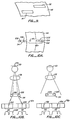
- An auto focusing system for use with the present invention will now be described with reference to Figs. 10A-10C. In Fig. 10A, a transmission/
reception slit pair 42x includestransmission slit 14x in the shape of a small square and receivingslit 32x including a pair ofvertical wires focus prisms center aperture 34 of theaperture structure 26. - Referring now to Fig. 10B, a top view of the
axis plane 45 depicts the operation of the autofocus system when the image of thesquare transmission slit 14x is in focus, i.e., the image ofslit 42x at theretina 12 is at theobject plane 50. The focusingprisms images slit 32x. Thewires images 112 and 114. The output of the vidicon tube for this configuration is depicted ingraphs 114B and 116B. - In Fig. 10B, the system is depicted where the image of
slit 42x at retina is out of focus, e.g., the retina is behind theobject plane 50. Theimages square transmission slit 14x are horizontally displaced so that thewires - The vidicon output signals can be utilized as part of a feedback system to adjust the optics of the system to center the
wires - Fig. 11 illustrates that a unique system of flare control may also be implemented in the present invention. Referring first back to Fig. 1, reflection of the
illumination beam 17 from the surface of theeye lens 28 causes a bright spot to form on the image. Referring now to Fig. 11, atransmission slit 14 and receiving slit 32 have transmission and receivinggrids closed areas grids closed areas 126 of thereceiving grid 122 would overlay theopen area 124 of thetransmission grid 120. - The
grids slits eye lens 28 and imaged at eye lens. Theimages 128 and 130 of the transmission and receivinggrids eye lens 28 are shown displaced vertically to better explain the invention. In practice theseimages closed areas 126 of receivinggrid image 130 would cover theopen areas 124 of thetransmission grid image 128. Theseopen areas 124 are the illuminated regions of the surface of theeye lens 28. Thus, theclosed areas 126 of the receiving grid block these illuminated regions from view through the receiving slit 32 and prevent flare of theeye lens 28 from appearing on the image. - It is important that the camera be positioned in the correct distance from the eye in order to achieve optimum focus. This is done by a simplifed automated system that can be understood with reference to Figure 5. Referring to Figure 5, a small
light emitting diode 200 is imaged through the receiving system via abeam splitter 202. This image is reflected by the eye and focused on the quad detector. - The operation of the system can be understood by analyzing three cases. First, if the eye is in the correct position and the slit scanning camera scans past the infrared image in the eye, there will be no relative movement of the image during the scan at the detector as the image will be properly focused at the detector. As there is no relative movement, this will flag that the eye is correctly spaced from the camera.
- Assuming that the eye is too close, there will be relative movement of the image as the image will be out of focus at the detector. This relative movement will have both magnitude and sign. The movement of the image across the detector segments will be, for example, from positive x to negative x as illustrated in Figure 12.
- Finally, if the eye is too far away, the magnitude will indicate the distance and the direction of movement will be opposite on the
quad detector 132 as illustrated in Figure 12. The out of focus of the image at the detector will be beyond optimum focus; relative image movement will thus be opposite. - Referring to Figure 12 it can be seen that centering of the eye in the x and y planes is straightforward.
- The above description of the invention is illustrative only and does limit its scope. For example, in applications where active optical elements are not required in the receiving slit, a drum having only transmission slits may be utilized. Additionally, different lens configurations other than the ones illustrated may be utilized to achieve the same effects. Alternative means for determining drum positioning and performing slit selection are within the skill of the art. Additionally, although a flash lamp has been described as the light source, a constant light source with a timed shutter mechanism could be substituted to perform the function selection features described above. Accordingly, the scope of the invention is determined by the appended claims.
Claims (10)
Applications Claiming Priority (2)
| Application Number | Priority Date | Filing Date | Title |
|---|---|---|---|
| US719779 | 1985-04-04 | ||
| US06/719,779 US4732466A (en) | 1985-04-04 | 1985-04-04 | Fundus camera |
Publications (2)
| Publication Number | Publication Date |
|---|---|
| EP0197761A2 true EP0197761A2 (en) | 1986-10-15 |
| EP0197761A3 EP0197761A3 (en) | 1988-04-06 |
Family
ID=24891330
Family Applications (1)
| Application Number | Title | Priority Date | Filing Date |
|---|---|---|---|
| EP86302446A Withdrawn EP0197761A3 (en) | 1985-04-04 | 1986-04-02 | Fundus camera |
Country Status (3)
| Country | Link |
|---|---|
| US (1) | US4732466A (en) |
| EP (1) | EP0197761A3 (en) |
| JP (1) | JPS61276534A (en) |
Cited By (2)
| Publication number | Priority date | Publication date | Assignee | Title |
|---|---|---|---|---|
| DE3714041A1 (en) * | 1987-04-28 | 1988-11-10 | Wolfdietrich Dr Med Steinhuber | Apparatus for examining and observing the eye |
| EP1798566A3 (en) * | 2005-12-14 | 2011-03-02 | Delphi Technologies, Inc. | Method for ephemeris assisted global positioning |
Families Citing this family (32)
| Publication number | Priority date | Publication date | Assignee | Title |
|---|---|---|---|---|
| US4902121A (en) * | 1988-10-04 | 1990-02-20 | Allergan Humphrey | Range detector for eye instrument having interrogating beam |
| US5220360A (en) * | 1990-10-24 | 1993-06-15 | Ophthalmic Imaging Systems, Inc. | Apparatus and method for topographical analysis of the retina |
| US6637882B1 (en) * | 1998-11-24 | 2003-10-28 | Welch Allyn, Inc. | Eye viewing device for retinal viewing through undilated pupil |
| ATE274833T1 (en) | 1998-11-24 | 2004-09-15 | Welch Allyn Inc | EYE EXAMINATION DEVICE TO VIEW THE RETINA THROUGH AN UNDILATED PUPILL |
| US7360895B2 (en) * | 2000-07-14 | 2008-04-22 | Visual Pathways, Inc. | Simplified ocular fundus auto imager |
| US7025459B2 (en) * | 2000-07-14 | 2006-04-11 | Visual Pathways, Inc. | Ocular fundus auto imager |
| EP1210905B1 (en) * | 2000-12-01 | 2007-05-09 | Nidek Co., Ltd. | Fundus camera |
| AU2004287478A1 (en) * | 2003-10-28 | 2005-05-19 | Welch Allyn, Inc. | Digital documenting ophthalmoscope |
| US7338167B2 (en) * | 2003-12-10 | 2008-03-04 | Joslin Diabetes Center, Inc. | Retinal imaging system |
| US7347549B2 (en) * | 2003-12-10 | 2008-03-25 | Bausch & Lomb Incorporated | Rapid switching slit scan image capture system |
| JP4505852B2 (en) * | 2004-04-13 | 2010-07-21 | 学校法人早稲田大学 | Fundus spectral imaging device |
| US7365856B2 (en) | 2005-01-21 | 2008-04-29 | Carl Zeiss Meditec, Inc. | Method of motion correction in optical coherence tomography imaging |
| US7805009B2 (en) * | 2005-04-06 | 2010-09-28 | Carl Zeiss Meditec, Inc. | Method and apparatus for measuring motion of a subject using a series of partial images from an imaging system |
| US7458685B2 (en) * | 2005-08-03 | 2008-12-02 | Carestream Health, Inc. | Automated fundus imaging system |
| EP2338407B1 (en) | 2009-12-23 | 2014-02-12 | OPTOPOL Technology Spolka Akcyjna | Device for visually examining the ocular fundus of a patient |
| DE102010050693A1 (en) | 2010-11-06 | 2012-05-10 | Carl Zeiss Meditec Ag | Fundus camera with stripe-shaped pupil division and method for recording fundus images |
| US9033510B2 (en) | 2011-03-30 | 2015-05-19 | Carl Zeiss Meditec, Inc. | Systems and methods for efficiently obtaining measurements of the human eye using tracking |
| ITFI20110085A1 (en) * | 2011-04-26 | 2012-10-27 | Strumenti Oftalmici C S O S R L Costruzioni | TOOL FOR ACQUISITION OF IMAGES OF THE EYE BACKGROUND |
| US8857988B2 (en) | 2011-07-07 | 2014-10-14 | Carl Zeiss Meditec, Inc. | Data acquisition methods for reduced motion artifacts and applications in OCT angiography |
| US9101294B2 (en) | 2012-01-19 | 2015-08-11 | Carl Zeiss Meditec, Inc. | Systems and methods for enhanced accuracy in OCT imaging of the cornea |
| US9456746B2 (en) | 2013-03-15 | 2016-10-04 | Carl Zeiss Meditec, Inc. | Systems and methods for broad line fundus imaging |
| DE102013007075A1 (en) | 2013-05-22 | 2014-11-27 | Rs Medizintechnik Gmbh | ophthalmoscope |
| EP3253276A1 (en) | 2015-02-05 | 2017-12-13 | Carl Zeiss Meditec AG | A method and apparatus for reducing scattered light in broad-line fundus imaging |
| WO2017025583A1 (en) | 2015-08-12 | 2017-02-16 | Carl Zeiss Meditec, Inc. | Alignment improvements for ophthalmic diagnostic systems |
| US11412928B2 (en) | 2017-08-11 | 2022-08-16 | Carl Zeiss Meditec, Inc. | Systems and methods for improved ophthalmic imaging |
| US11000187B2 (en) | 2017-09-07 | 2021-05-11 | Carl Zeiss Meditec, Inc. | Systems and methods for improved montaging of ophthalmic imaging data |
| WO2019138916A1 (en) * | 2018-01-10 | 2019-07-18 | 株式会社ニデック | Fundus imaging device |
| JP6958367B2 (en) * | 2018-01-10 | 2021-11-02 | 株式会社ニデック | Fundus photography device |
| EP3941333A1 (en) | 2019-03-20 | 2022-01-26 | Carl Zeiss Meditec, Inc. | A patient tuned ophthalmic imaging system with single exposure multi-type imaging, improved focusing, and improved angiography image sequence display |
| EP4007518A1 (en) | 2019-08-01 | 2022-06-08 | Carl Zeiss Meditec, Inc. | Ophthalmic imaging with k-mirror scanning, efficient interferometry, and pupil alignment through spatial frequency analysis |
| JP2021142173A (en) * | 2020-03-13 | 2021-09-24 | 株式会社トプコン | Ophthalmologic device, control method thereof, and program |
| WO2022117646A1 (en) | 2020-12-02 | 2022-06-09 | Carl Zeiss Meditec, Inc. | Alignment guidance user interface system |
Citations (4)
| Publication number | Priority date | Publication date | Assignee | Title |
|---|---|---|---|---|
| GB1041249A (en) * | 1962-10-02 | 1966-09-01 | Nippon Kogaku Kk | Optical instruments |
| US3547512A (en) * | 1968-04-16 | 1970-12-15 | Research Corp | Optical apparatus providing focalplane-specific illumination |
| US4170398A (en) * | 1978-05-03 | 1979-10-09 | Koester Charles J | Scanning microscopic apparatus with three synchronously rotating reflecting surfaces |
| US4251139A (en) * | 1977-05-20 | 1981-02-17 | Canon Kabushiki Kaisha | Eye examining instrument |
Family Cites Families (5)
| Publication number | Priority date | Publication date | Assignee | Title |
|---|---|---|---|---|
| US3819256A (en) * | 1972-08-11 | 1974-06-25 | H Borough | Apparatus for refracting the eye |
| US3888569A (en) * | 1973-05-09 | 1975-06-10 | Tropel | Apparatus and method of measuring the refractive error of an eye |
| JPS5529316A (en) * | 1978-08-18 | 1980-03-01 | Canon Kk | Eyeground camera |
| JPS57165735A (en) * | 1981-04-04 | 1982-10-12 | Nippon Kogaku Kk <Nikon> | Device for measuring refracting power in optical system |
| DE3245939C2 (en) * | 1982-12-11 | 1985-12-19 | Fa. Carl Zeiss, 7920 Heidenheim | Device for generating an image of the fundus |
-
1985
- 1985-04-04 US US06/719,779 patent/US4732466A/en not_active Expired - Fee Related
-
1986
- 1986-04-02 EP EP86302446A patent/EP0197761A3/en not_active Withdrawn
- 1986-04-04 JP JP61076875A patent/JPS61276534A/en active Pending
Patent Citations (4)
| Publication number | Priority date | Publication date | Assignee | Title |
|---|---|---|---|---|
| GB1041249A (en) * | 1962-10-02 | 1966-09-01 | Nippon Kogaku Kk | Optical instruments |
| US3547512A (en) * | 1968-04-16 | 1970-12-15 | Research Corp | Optical apparatus providing focalplane-specific illumination |
| US4251139A (en) * | 1977-05-20 | 1981-02-17 | Canon Kabushiki Kaisha | Eye examining instrument |
| US4170398A (en) * | 1978-05-03 | 1979-10-09 | Koester Charles J | Scanning microscopic apparatus with three synchronously rotating reflecting surfaces |
Cited By (2)
| Publication number | Priority date | Publication date | Assignee | Title |
|---|---|---|---|---|
| DE3714041A1 (en) * | 1987-04-28 | 1988-11-10 | Wolfdietrich Dr Med Steinhuber | Apparatus for examining and observing the eye |
| EP1798566A3 (en) * | 2005-12-14 | 2011-03-02 | Delphi Technologies, Inc. | Method for ephemeris assisted global positioning |
Also Published As
| Publication number | Publication date |
|---|---|
| EP0197761A3 (en) | 1988-04-06 |
| JPS61276534A (en) | 1986-12-06 |
| US4732466A (en) | 1988-03-22 |
Similar Documents
| Publication | Publication Date | Title |
|---|---|---|
| US4732466A (en) | Fundus camera | |
| US4960327A (en) | Optical system in a lasar scanning eye fundus camera | |
| US4201456A (en) | Method and apparatus for detecting the focusing condition of an optical system | |
| US4712894A (en) | Ophthalmoscopic instrument having working position detecting means | |
| JPS6454B2 (en) | ||
| JP3886191B2 (en) | Lens meter | |
| US4544248A (en) | Ophathalmoscopic camera having a focus detecting system | |
| US4429964A (en) | Mirror-reflex camera with electronic rangefinder | |
| US4963912A (en) | Camera apparatus having means for setting the position of an optical grating at a desired location in the viewfinder | |
| JPH0323167B2 (en) | ||
| US4468104A (en) | Working distance detecting device for ophthalmic instruments | |
| JP2001340301A (en) | Ophthalmography | |
| JPS649855B2 (en) | ||
| US4200786A (en) | Electrooptical focusing apparatus for photographic cameras | |
| JP3005815B2 (en) | Ocular microscope | |
| JPS623122Y2 (en) | ||
| JPH0346774B2 (en) | ||
| JPH044891B2 (en) | ||
| US5694198A (en) | Apparatus including waveform rectifying means and method for eye examination | |
| JPS6260645B2 (en) | ||
| JPH0226205B2 (en) | ||
| EP0190824A2 (en) | Photometer for use with a microscope | |
| JP2925165B2 (en) | Autofocus fundus camera | |
| US4428653A (en) | Mirror reflex camera with an electronic range finder | |
| JP3005810B2 (en) | Ocular microscope |
Legal Events
| Date | Code | Title | Description |
|---|---|---|---|
| PUAI | Public reference made under article 153(3) epc to a published international application that has entered the european phase |
Free format text: ORIGINAL CODE: 0009012 |
|
| AK | Designated contracting states |
Kind code of ref document: A2 Designated state(s): CH DE FR GB LI |
|
| RAP1 | Party data changed (applicant data changed or rights of an application transferred) |
Owner name: ALLERGAN HUMPHREY |
|
| PUAL | Search report despatched |
Free format text: ORIGINAL CODE: 0009013 |
|
| AK | Designated contracting states |
Kind code of ref document: A3 Designated state(s): CH DE FR GB LI |
|
| 17P | Request for examination filed |
Effective date: 19880915 |
|
| 17Q | First examination report despatched |
Effective date: 19881026 |
|
| STAA | Information on the status of an ep patent application or granted ep patent |
Free format text: STATUS: THE APPLICATION HAS BEEN WITHDRAWN |
|
| 18W | Application withdrawn |
Withdrawal date: 19910418 |
|
| R18W | Application withdrawn (corrected) |
Effective date: 19910418 |
|
| RIN1 | Information on inventor provided before grant (corrected) |
Inventor name: HUMPHREY, WILLIAM E. |