EP0197696B1 - Kernbohrüberwachungssystem - Google Patents
Kernbohrüberwachungssystem Download PDFInfo
- Publication number
- EP0197696B1 EP0197696B1 EP86302156A EP86302156A EP0197696B1 EP 0197696 B1 EP0197696 B1 EP 0197696B1 EP 86302156 A EP86302156 A EP 86302156A EP 86302156 A EP86302156 A EP 86302156A EP 0197696 B1 EP0197696 B1 EP 0197696B1
- Authority
- EP
- European Patent Office
- Prior art keywords
- inner barrel
- core
- signal
- reflectable
- advancement
- Prior art date
- Legal status (The legal status is an assumption and is not a legal conclusion. Google has not performed a legal analysis and makes no representation as to the accuracy of the status listed.)
- Expired
Links
- 238000012806 monitoring device Methods 0.000 title 1
- 238000005553 drilling Methods 0.000 claims abstract description 33
- 239000012530 fluid Substances 0.000 claims abstract description 21
- 238000012544 monitoring process Methods 0.000 claims abstract description 18
- 238000005259 measurement Methods 0.000 claims description 20
- 238000000034 method Methods 0.000 claims description 16
- 238000001514 detection method Methods 0.000 claims description 5
- 239000000463 material Substances 0.000 claims description 5
- 230000007246 mechanism Effects 0.000 claims description 5
- 238000012545 processing Methods 0.000 claims description 3
- 230000009467 reduction Effects 0.000 claims description 3
- 230000004044 response Effects 0.000 claims description 3
- 229920005830 Polyurethane Foam Polymers 0.000 claims description 2
- 230000005540 biological transmission Effects 0.000 claims description 2
- 239000011496 polyurethane foam Substances 0.000 claims description 2
- 230000002745 absorbent Effects 0.000 claims 4
- 239000002250 absorbent Substances 0.000 claims 4
- 238000009530 blood pressure measurement Methods 0.000 claims 1
- 238000011084 recovery Methods 0.000 claims 1
- 230000000007 visual effect Effects 0.000 claims 1
- 239000003990 capacitor Substances 0.000 description 29
- 238000010586 diagram Methods 0.000 description 10
- 230000006870 function Effects 0.000 description 8
- 230000008569 process Effects 0.000 description 4
- 239000006260 foam Substances 0.000 description 3
- 239000010453 quartz Substances 0.000 description 3
- VYPSYNLAJGMNEJ-UHFFFAOYSA-N silicon dioxide Inorganic materials O=[Si]=O VYPSYNLAJGMNEJ-UHFFFAOYSA-N 0.000 description 3
- 239000004593 Epoxy Substances 0.000 description 2
- 238000004891 communication Methods 0.000 description 2
- 239000013078 crystal Substances 0.000 description 2
- 230000007423 decrease Effects 0.000 description 2
- 239000007788 liquid Substances 0.000 description 2
- 244000186140 Asperula odorata Species 0.000 description 1
- 235000008526 Galium odoratum Nutrition 0.000 description 1
- 239000006096 absorbing agent Substances 0.000 description 1
- 230000009471 action Effects 0.000 description 1
- XAGFODPZIPBFFR-UHFFFAOYSA-N aluminium Chemical compound [Al] XAGFODPZIPBFFR-UHFFFAOYSA-N 0.000 description 1
- 229910052782 aluminium Inorganic materials 0.000 description 1
- 150000001875 compounds Chemical class 0.000 description 1
- 238000010276 construction Methods 0.000 description 1
- 239000000356 contaminant Substances 0.000 description 1
- 230000001419 dependent effect Effects 0.000 description 1
- 239000010432 diamond Substances 0.000 description 1
- 229910003460 diamond Inorganic materials 0.000 description 1
- 238000000605 extraction Methods 0.000 description 1
- 239000011521 glass Substances 0.000 description 1
- 230000000977 initiatory effect Effects 0.000 description 1
- HFGPZNIAWCZYJU-UHFFFAOYSA-N lead zirconate titanate Chemical compound [O-2].[O-2].[O-2].[O-2].[O-2].[Ti+4].[Zr+4].[Pb+2] HFGPZNIAWCZYJU-UHFFFAOYSA-N 0.000 description 1
- 230000013011 mating Effects 0.000 description 1
- 239000003129 oil well Substances 0.000 description 1
- 239000002245 particle Substances 0.000 description 1
- 230000002093 peripheral effect Effects 0.000 description 1
- 230000008439 repair process Effects 0.000 description 1
- 239000011435 rock Substances 0.000 description 1
- 239000002689 soil Substances 0.000 description 1
Images

Classifications
-
- E—FIXED CONSTRUCTIONS
- E21—EARTH OR ROCK DRILLING; MINING
- E21B—EARTH OR ROCK DRILLING; OBTAINING OIL, GAS, WATER, SOLUBLE OR MELTABLE MATERIALS OR A SLURRY OF MINERALS FROM WELLS
- E21B25/00—Apparatus for obtaining or removing undisturbed cores, e.g. core barrels or core extractors
-
- E—FIXED CONSTRUCTIONS
- E21—EARTH OR ROCK DRILLING; MINING
- E21B—EARTH OR ROCK DRILLING; OBTAINING OIL, GAS, WATER, SOLUBLE OR MELTABLE MATERIALS OR A SLURRY OF MINERALS FROM WELLS
- E21B45/00—Measuring the drilling time or rate of penetration
Definitions
- the present invention pertains in general to apparatus for drilling a well core and, more particularly, to such apparatus utilizing a measurement device for monitoring the advancement of the well core in the inner barrel of the apparatus during the coring operation.
- the invention also pertains to a method of well core drilling involving such monitoring.
- U.S. Patent No. 2,555,272 discloses a clockwork instrument disposed in contact with a plug that seals the inner barrel.
- the clockwork instrument is in contact with the upper end of the inner barrel through a retracting wire. As the instrument is urged upward by the core entering the inner barrel, the retracting mechanism operates numerous gears to record core length information.
- U.S. Patent No. 3,344,872 discloses a device having a chain disposed in the inner barrel from a weight measuring device. As the core moves upward into the inner barrel, the links of the chain are slowly removed, thus reducing the weight of the chain. This weight is measured and data transmitted through a transducer to the surface.
- the present invention provides a well core drilling apparatus comprising a boring device for boring a well core at the bottom of a bore hole and causing the well core to travel upwardly in an inner barrel of the boring device as it is being bored, and monitoring means associated with the inner barrel for monitoring the advancement of the well core into the inner barrel so as to provide an indication at the surface of an advancement which is slower than a predetermined advancement, characterized in that said monitoring means comprises: generating means for repeatedly generating a reflectable signal at the upper end of the inner barrel and for directing such reflectable signal downwardly toward a well core as the well core is being bored; detecting means for detecting the energy of each reflectable signal that reflects upwardly to the upper end of the inner barrel; measuring means for measuring the time interval between the generation of each reflectable signal and the detection of the reflected energy and calculating distance; storing means for storing the calculated distances; processing means for comparing successive distances to determine a rate of advancement of the core into the inner barrel, comparing that determined rate with a predetermined value, and generating a
- the present invention also provides a method of well core drilling wherein a boring device bores a well core set at the bottom of a bore hole and causes the well core to travel upwardly in an inner barrel of the boring device as it is being bored, and the advancement of the well core into the inner barrel is monitored by a monitoring mechanism associated with the inner barrel which provides an indication at the surface of an advancement which is slower than a predetermined advancement, characterised in that the monitoring of the core advancement comprises the steps of:
- the fault signal transmitted to the surface indicates the presence of a jam or a default of some type.
- the fault signal operates a pressure valve in the coring device that relieves the pressure therein. This reduction in pressure is measured at the surface and appropriate action is taken to prevent damage to the coring device.
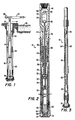
- FIGURE 1 there is illustrated a cross sectional diagram of a coring device of the present invention inserted in a bore hole.
- the coring device is comprised of a surface pipe 10 which is connected to an inside drill pipe 12 which is disposed in the upper end of the bore hole and extend downward into the bottom of the bore hole.
- the inside drill pipe 12 is connected to an inside collar 14 which has a diameter that is larger than the inside drill pipe 12.
- the inside collar 14 is connected at the lower end thereof to a core barrel 16, which has a coring bit 18 disposed on the end thereof and proximate the bottom of the bore hole.
- mud or similar drilling fluid is pumped down through the pipe sections 10, 12 and the collar 14 to the core barrel 16 to exit at the coring bit 18. This fluid then passes around the coring bit 18 and back up through the bore hole about the apparatus.
- the annulus formed around the apparatus varies as a function of depth and as a function of the diameter of the apparatus. Proximate the core barrel 16 is an annulus 20, proximate the inside collar 14 is an annulus 22 and proximate the inside drill pipe 12 is an annulus 24.
- the pressure varies as the fluid passes from annulus 20 to the annulus 22 to the annulus 24, depending upon the restriction and the weight of the drilling fluid.
- the drilling fluid is delivered to a mud pit 26 on the surface which is at atmospheric pressure.
- the pressure in the stand pipe is measured with a stand pipe pressure gauge 28 disposed at the surface of the bore hole. As will be described hereinbelow, this pressure is monitored to determine certain operating properties of the drilling operation.
- This pressure in some applications, can be varied with apparatus disposed at the bottom of the bore hole such that information gathering devices disposed at the bottom of the bore hole can transmit data via pressure variations.
- U.S. Patent No. 4,070,628, issued to Westlake et al and U.S. Patent No. 3,964,556, issued to Gearhart et al and assigned to Gearhart-Owen Industries Inc. both of which are incorporated herein by reference.
- the core barrel 16 is comprised of an outer barrel 30 which has the core bit 18 attached to the end thereto.
- the outer barrel 30 rotates with the drill string with an inner barrel 32 disposed internal thereto and rotatable with respect thereto.
- the inner barrel 32 is threadedly engaged with an adapter sub 34 for enclosing the monitoring apparatus, the adapter sub 34 being threadedly engaged with a flow tube 36.
- the flow tube 36 is threadedly engaged with a retainer 38 which has bearings 40 disposed thereabout.
- the bearings are supported by a bearing stop 42 and are operable to allow the flow tube to rotate with respect to the outer barrel 30.
- the outer barrel 30 is threadedly engaged to a safety joint box 44 through an adapter 46.
- the safety joint box 44 is in turn threadedly engaged with a valve adapter housing 48.
- the valve adapter housing 48 is threadedly engaged with the remaining portions of the drill string.
- the valve adapter housing 48 includes a valve 50 with control circuitry 52 and battery supply 54 associated therewith.
- a switch 56 is disposed in the lower end of the interior of the valve adapter housing 48 for controlling the operation of the valve 50.
- the valve 50 is operable to relieve pressure within the drill string by bypassing all or a portion of the drilling fluid to the exterior of the drill string, as will be described hereinbelow.
- the drilling fluid is passed down the center of the drill string through a hollow central portion 58. Drilling fluid passes about the valve 50 and the associated control circuitry 52 and battery 54. The drilling fluid then passes down through the flow tube 36 and through an annulus 60 between the outer barrel 30 and the inner barrel 32.
- the inner barrel 32 is threadedly engaged at the lower end thereof to an inner barrel sub 62.
- the inner barrel sub 62 is threadedly engaged on the lower end thereof to a core catcher sub 64 for receiving the core during drilling thereof.
- a piston 68 is disposed in the lower end of the inner barrel and protruding slightly outward from the core catcher sub 64.
- An O-ring 70 is disposed around the piston 68 and seated in the inner barrel sub at the lower end thereof.
- the piston 68 has a valve 72 disposed at the center thereof that is operable to release pressure in the inner barrel 32 when the valve contacts the top of the core. The pressure is relieved through the valve 72 and through the bottom of the piston 68. In operation, the piston provides a seal for the inner barrel 32 until the core is contacted. At that point, pressure within the inner barrel 32 is relieved and the piston 68 urged upward by the core into the inner barrel 32. The operation of this piston is fully described in EP-A-182498.
- a cylindrical sponge 74 is disposed on the interior walls of the inner barrel 32 and is slideably disposed therein.
- the cylindrical sponge 74 is attached to a cylindrical liner on the exterior thereof, the cylindrical liner operable to slide against the interior walls of the inner barrel 34.
- the liner is fabricated from aluminum and the sponge 74 is fabricated from polyurethane foam.
- the foam is comprised of a plurality of cells, some of which are open and some of which are closed. The use and construction of this foam is fully disclosed in U.S. Patent No. 4,312,414, issued to the present applicant.
- the sponge 74 is dimensioned to define a bore through the middle thereof for receiving the core.
- the interior of the inner barrel is pressurized with a liquid to prevent contaminants from coming into contact with the exposed surface of the sponge 74 and being absorbed into the interstices thereof. As described above, the pressure is equilibrated when the valve 72 in the piston 68 is opened upon contact with the core.
- a Sonic Core Monitor (SCM) 78 is disposed in the adapter 34 and is in sonic communication with the interior of the inner barrel 32.
- the SCM 78 is operable to transmit ultrasonic pulses through the pressurized liquid in the inner barrel 32 and receive reflections from the upper surface of the piston 68. In operation, it is only important that the piston 68, or any device that precedes the core up the barrel, has a reflective surface.
- the SCM device 78 is connected to the switch 56 through an extension rod 76 to activate the valve 50 when predetermined conditions are met. When these predetermined conditions are met, the valve 50 is activated and fluid is bypassed from the flow going into the core barrel 16 as will be described hereinbelow, the SCM device 78 makes a number of measurements and correlates these measurements to distinguish between spurious noise and other extraneous sources of noise that are in the bandwith of the SCM device 78.
- the SCM device 78 is selfcontained such that no interface is required with the surface. If movement is not detected over a predetermined period of time, the valve 50 is opened to cause a sudden pressure drop and indicate to the surface that the core is not proceeding upward into the inner barrel 32.
- FIGURE 3 there is illustrated a cross sectional diagram of the lower end of the core barrel 16 showing a core 80 extending upward into the inner barrel 32 and preceded by the piston 68.
- the SCM device 78 outputs a transmitted pulse at a predetermined frequency, as noted by the dotted lines 82. In the preferred embodiment, this frequency is in the ultrasonic range.
- the reflection from the surface of the piston 68 is noted by the dotted lines 84.
- the SCM device 78 determines the length of time required for the pulse to travel to the surface of the piston 68 and back to the SCM device 78. The distance can then be calculated since the transmission speed for the given medium is known.
- the use of ultrasonic waves for determining distance has a number of disadvantages. Some of the disadvantages are that spurious signals can resemble a reflected pulse and cause errors in the measurement. The spurious noises can result from vibrations in the core barrel 16 or in reflections from particles in the medium between the SCM 78 and the piston 68.
- the measurement is made a predetermined number of times and the various measurements compared with each other to determine if a correlation exists. If so, a valid measurement exists. However, if the measurements vary, this indicates that they are due to other sources than the mere reflection off the surface of the piston 68.
- the sponge 74 in addition to absorbing the subterranean fluids from the core, also acts as a sound absorber on the sides of the inner barrel 32. Since the structure of the foam utilizes a semi-opened celled structure, the attenuation of waves impinging upon the surface thereof is high. This significantly reduces internal reflections, thus improving the measurement of distance between the SCM 78 and the piston 68.
- the information regarding distance versus time as the core 80 proceeds upward into the inner barrel 32 is stored in the SCM 78 for later retrieval therefrom. Therefore, the SCM 78 provides two functions. First it measures and records distance versus time for the entire coring process and stores this information at the bottom of the bore hole. This information can at a later time be analyzed and compared with drilling records on the surface. Secondly, the SCM 78 determines if the core is entering the inner barrel 32 at a sufficient rate to indicate proper coring. If the coring procedure is determined to be at a rate slower than a predetermined rate, the SCM 78 activates a valve to reduce pressure, this reduction in pressure is visible at the surface. The operator can then terminate the coring procedure and withdraw the core barrel 16 to determine what the cause of the coring fault is. With early detection of the coring fault, further damage can be prevented, thus reducing the cost per foot of core.
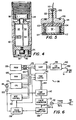
- FIGURE 4 there is illustrated a cross sectional diagram of the adapter sub 34 for housing the SCM 78.
- the SCM 78 is comprised of a control circuit 86 and a battery unit 88.
- the control circuit 86 and battery unit 88 are housed in a SCM housing 90 which is a cylindrical unit for slideably fitting within the adapter sub 34.
- a piezoelectric transducer 92 is mounted in a transducer housing 94.
- a layer of material 96 is disposed at the bottom of the adapter sub 34 and is operable to protect the transducer 92 from the interior of the inner barrel 32.
- the layer 96 can be fabricated from any type of material that will seal the inner barrel 32 and is transparent to ultrasonic waves, such as a plate fabricated from glass or quartz.
- the SCM housing 90 is inserted into the adapter sub 34 and a lock ring 98 disposed over the top thereof and threadedly engaged with the innersides of the adapter sub 34.
- the SCM housing 90 is designed such that it will survive the G-forces experienced at the bottom of the bore hole.
- FIGURE 5 there is illustrated a cross sectional diagram of the transducer 92 and transducer housing 94.
- the housing 94 has a cavity 100 formed in the end thereof with a conduit 102 extending from the bottom of the cavity 100 to the rear portion along the axis of the housing 94.
- the piezoelectric transducer 92 is fabricated from a lead titanate zirconate piezoelectric device which is manufactured by EDO Corporation, Model No. EC-64. The dimensions of the transducer are approximately one centimeter thick with a 2.5 centimeter diameter.
- the transducer 92 is mounted on the bottom of the cavity 100 with a flexible epoxy 104 of the type 2216 manufactured by 3M Corporation.
- the epoxy is only adhered to one surface of the piezo transducer 92 such that the sides thereof are disposed from the sides of the cavity 100.
- the remainder of the cavity and the outer surface of piezo transducer 92 are covered by RTV which is a vulcanized compound manufactured by Dow Corning Corporation.
- a groove 106 is disposed on the backside of the housing 94 for receiving an O-ring.
- the groove is disposed on an annular surface perpendicular to the central axis of the housing 94 for mating with the bottom of the SCM housing 90.
- a neck portion 108 is operable to insert through an orifice in the bottom of the SCM housing 90 for communication with the control circuit 86.
- a wire 110 is disposed through the conduit 102 for connection to the backside of the transducer 92 and to the control circuit 86.
- the opposite side of the transducer 92 is connected through wires 112 and 114 to the peripheral edge of the transducer housing 94. This allows one side of the transducer 92 to be connected to the housing, which functions as one polarity of the power supply potential that drives the control circuit 86.
- FIGURE 6 there is illustrated a schematic block diagram of the control circuit 86 in the SCM 78.
- a Central Processing Unit (CPU) 116 is provided that utilizes a microprocessor of the type CDP18O2 manufactured by RCA Corporation.
- a quartz crystal 118 is provided and connected to the CPU 116 to provide a time base therefor. This time base is tapped off from the quartz crystal 118 through a buffer circuit 120 for the rest of the circuit.
- the CPU 116 is connected through to data out ports thereof to a data bus 122 and from the address ports thereof to an address bus 124.
- the CPU 116 is operable to control the transducer 92 and the operation thereof.
- a Random Access Memory (RAM) 126 is connected to the data and address buses 122 and 124 and is operable to store data therein for later retrieval.
- the RAM 126 can store programmed instructions for use by the CPU 116.
- a Programmable Read Only Memory (PROM) 128 is also connected to the data bus 122 and address bus 124 and is operable to store predetermined programmed instructions for use by the CPU 116.
- the address bus 124 is also connected to a miscellaneous control circuit 130 providing various instructions, as will be described hereinbelow.
- a pulse generator 132 is provided which is controlled by the CPU 116 to output a pulse having a voltage level of around 70 to 80 volts for input to the transducer 92 on a line 134.
- the pulse is transmitted from the transducer 92 over a very short duration of time.
- the line 134 is also connected to the input of a limiter/amplifier 136 for sensing the reflected wave received by the transducer 92.
- the output of the limiter/amplifier 136 is input to a pulse detector 138, which also receives the clock signal output by the buffer 120.
- the pulse detector 138 is operable to determine when a pulse is present. This information is then relayed to the input of a time latch circuit 140.
- the time latch circuit 140 receives data from a time counter 142 to latch the data therein.
- the time counter 142 is initiated when the pulse is generated from the pulse generator 132 and provides continually changing data on a bus 144 between the time counter 142 and the time latch circuit 140.
- this data is latched into the time latch circuit 140 by the pulse detector 138.
- the output of the time latch 140 is connected to the data bus 122 and the miscellaneous control circuit 130 is operable to store this data in a predetermined location in the RAM 126.
- the time counter 142 is initiated simultaneously with initiation of the pulse generator 132.
- the pulse generator 132 generates a spike of around 70 to 80 volts to elicit a power output from the transducer 92 of approximately 5 watts.
- the time counter 142 begins to count from the time that the pulse is generated and continues to count until a reflected pulse is detected by the pulse detector 138, at which time the time latch circuit 140 latches the count on the output of the time counter 142.
- This data is stored in the RAM 126, the time counter 142 reset and another pulse generated by the pulse generator 132. This is continued a predetermined number of times over a short interval of time and all of the data stored in the RAM 126.
- This data is then analyzed by the CPU 116 in accordance with the program stored in the PROM 128 to determine if the data correlates; that is, it is necessary that subsequent time measurements of the transmitted/reflected wave be compared to determine if spurious noise is present.
- This can be any kind of algorithm which requires, for example, a percent of the responses for a given measurement to be within approximately five percent of each other. The algorithm can be more complicated to alleviate any discrepancies due to spurious noise.
- the control circuit 86 After the measurement has been validated, it is stored in RAM 126 at a predetermined address in associated with time information. This time information can be generated in the time counter 142 or it can be extracted from an internal clock in the CPU 116 (not shown). Another measurement is then taken after a predetermined period of time. It is not necessary to continually take measurements since this amount of data would be overburdensome and require a large amount of memory. This is due to the fact that the measurement is relatively fast as compared to the overall drilling operation. Therefore, between each measurement, the control circuit 86 goes into a "power down" mode to conserve battery power.
- this data is stored with the previous data and the rate at which the core length is entering the inner barrel 32 is determined. This rate is compared with a predetermined value to provide an indication as to whether the core is moving into the barrel. If the rate is acceptable, the CPU 116 can then output a "jam" signal, which is stored in the PROM 128 for input to a Universal Asynchronous Receiver Transmitter (UART) 146 for output through an input/output (I/O) buffer 148 to a data acquisition terminal 150.
- UART Universal Asynchronous Receiver Transmitter
- I/O input/output
- the jam signal can be generated immediately after determining that the rate is below a predetermined level or, alternatively, the measurement can be made again at a later time and the rate reevaluated to determine if the core is in fact jammed. This will primarily be a function of the application since in some applications hard rock may decrease the rate of coring below the predetermined level without actually indicating a jammed condition. This is a function of the program and can be varied
- the jammed signal When the jammed signal is transmitted from the terminal 150, it is connected to the switch 56 to control the valve 50 to relieve the pressure in the drill string. As described above, this indicates to the operator from the surface that the core is no longer moving up into the barrel.
- the UART 146 and the I/O buffer 148 are also operable to interface with terminal 150 that allows an external unit to extract data from the RAM 126. This is utilized when the coring device is pulled back to the surface and the SCM 78 removed for analysis. The data provides a profile of time versus distance of the coring process. This can be compared with the drilling speed and other parameters which are normally recorded at the surface.
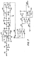
- FIGURE 7 there is illustrated a schematic block diagram of the limiter/amplifier 136.
- the line 134 from the transducer 92 is input to a capacitor 137 through a series resistor 139.
- a diode 141 is connected between the junction of the resistor 139 and capacitor 137 and ground with the cathode thereof connected to ground.
- the resistor 139 and diode 141 provide a limiting function to the input circuit of the limiter/amplifier 136.
- the other side of the capacitor 137 is connected to the negative input of an op amp 143 through a series resistor 145.
- the positive input of the op amp 143 is connected to a reference voltage.
- a feedback network is comprised of a parallel connected inductor 147, capacitor 149 and resistor 151.
- One side of this parallel configuration is connected to the negative input of the operational amp 143 and the other end thereof connected to a node 152.
- the node 152 has two parallel diodes 154 and 156 connected thereto and oriented in opposite directions with one end of the parallel pair connected to the node 152 and the other end thereof connected to the output of the op amp 143.
- the parallel inductor 147, capacitor 149 and resistor 151 perform a bandpass function when used in conjunction with the op amp 143.
- the output of the op amp 143 is connected through a capacitor 158 to the cathode of a diode 160.
- a diode 162 is also connected to the other side of the capacitor 158 and to the reference voltage on the cathode thereof.
- the anode of the diode 160 is connected to a node 164.
- the node 164 is also connected to a reference voltage through a parallel capacitor 166 and resistor 168.
- the diodes 160 and 162 and the diodes 154 and 156 form a detector when used in conjunction with the op amp 143 to detect the pulse.
- the node 164 with the detected output therefrom is input to the positive input of an op amp 170 through two series resistors 172 and 174.
- a capacitor 180 is connected between the conjunction of the resistors 172 and 174 and the output of the op amp 170.
- a feedback resistor 176 is connected between the negative input of the op amp 170 and the output thereof.
- the op amp 170 has the negative input connected to the reference voltage through a resistor 178 and the positive input thereof connected to the reference voltage through a capacitor 182.
- the op amp 170 is configured as a low pass amplifier to provide a low pass filter for the detected output.
- the output of the op amp 170 is input to the negative input of an op amp 184 through a series connected capacitor 186 and resistor 188.
- the positive input of the op amp 184 is connected to the reference voltage and the feedback network comprised of a parallel resistor 190 and capacitor 192 is connected between the output and negative input of the op amp 184.
- the op amp 184 is configured as a differentiator.
- the output of the op amp 184 is input to the negative input of a comparator 194 through a series resistor 196.
- the positive input of comparator 194 is connected through a resistor 200 to the reference voltage and through a resistor 202 to a node 204.
- the node 204 is connected through a diode 206 to the output of the comparator 194 with the anode thereof connected to the resistor 202.
- the node 204 is connected to one side of a variable resistor 208, the other side of which is connected to the negative input of the comparator 194 through a resistor 198.
- the other side of the variable resistor is also connected to ground through a diode 210, the cathode of which is connected to ground.
- the comparator 194 is operable as a threshold detector and trigger with a variable threshold provided by the variable resistor 208.
- the supply voltage is approximately 5.0 volts with the reference voltage being approximately 2.5 volts.
- the resistor 139 and diode 141 provide a limit of approximately 3.5 volts such that a higher voltage will not be impressed across the op amp 143.
- FIGURE 8 there is illustrated a schematic diagram of the pulse generator 132.
- the input signal from the CPU 116 is input to the base of an NPN transistor 212 through a series resistor 214 with a shunt resistor 216 disposed between the base of the transistor 212 and ground.
- the transistor 212 has its emitter connected to ground and the collector thereof connected to the base of a PNP transistor 218 through a inductor 220.
- the transistor 218 has the emitter thereof connected to the positive voltage supply with a bias resistor 222 connected between the emitter and base thereof to provide bias therefor.
- the collector of the transistor 212 is connected to the base of a NPN transistor 224 through a series capacitor 226.
- a diode 228 and resistor 230 are connected in parallel and this parallel configuration shunted across the base of the transistor 224 to ground with the cathode of the diode 228 connected to the base thereof.
- the transistor 224 has the emitter thereof connected to ground and the collector thereof connected to the base of a PNP transistor 232 through a series resistor 234.
- the transistor 232 is configured similar to the transistor 218 with a bias resister 236 connected across the emitter and base thereof.
- the capacitor 226 also couples the collector of the transistor 212 to the collector of a PNP transistor 238, the emitter of which is connected to the collector of the transistor 232 through a series resistor 240 and the base of which is connected to the emitter of the transistor 232 through a series resistor 242.
- the base of the transistor 238 is also connected to ground through a series resistor 244 and three series diodes 246, the cathodes of which are oriented toward ground.
- the collector of the transistor 224 is connected to the base of an NPN transistor 248 through a parallel configured resistor 250 and capacitor 252.
- the transistor 248 also has the base thereof connected to ground through a resistor 254, the emitter thereof connected to ground and the collector thereof connected to the emitter of the transistor 238 through a series diode 256, the anode thereof connected to the emitter of the transistor 238.
- the collector of the transistor 232 is also connected through a resistor 259 to a current mirror comprised of a transistor 258 and a transistor 260, the emitters of which are connected to ground through a resistor 262.
- the high current side of the current mirror transistor 260 is connected to the collector of the transistor 218 through a series resistor 264 and a series resistor 266.
- a capacitor 268 is disposed between the junction between the resistors 264 and 266 and ground.
- the capacitor 268 has a value of approximately 3.3 microfarads and is operable to store a large amount of charge therein.
- the output of the current mirror on the emitter of the transistor 260 is input to the base of an NPN transistor 270, the emitter of which is connected to ground and the collector of which is connected to the transducer 92 through a series capacitor 272.
- a zener diode 274 is disposed between the collector of the transistor 270 and ground with the cathode thereof connected to the collector.
- the collector of the transistor 270 is driven with a series inductor 276 from the collector of a PNP transistor 278.
- the collector of the PNP transistor 278 is also connected to the collector of the transistor 248, the transistor 248 shunting the collector to ground.
- the emitter of the transistor 278 is connected to the positive side of the capacitor 268 with a diode 280 connected between the collector and the emitter thereof.
- a resistor 282 is connected between the collector Of transistor 270 and ground.
- a signal is received on the base of the transistor 212 which causes current to flow through the transistor 218 to charge up capacitor 268 through resistor 264.
- Transistor 224 is also turned on momentarily by the signal that is ac coupled through the capacitor 226 to cause transistor 232 and transistor 248 to conduct.
- Transistor 232 supplies current to the control side of the current mirror on collector of transistor 258 which in turn turns on transistor 270 to pull one side of the inductor 276 to ground. Since transistor 248 is also turned on by a transistor 224, the inductor 276 is essentially placed in parallel with the capacitor 268.
- the circuit of FIGURE 8 allows the capacitor 268 to charge and this charge is then stored in the inductor 276. This requires one-half of the cycle of the resonant frequency of the parallel combination of the capacitor 268 and inductor 276. On the second half of the cycle, the charge on the capacitor 268 decreases, turning off transistor 278 and transistor 270 also turns off, thus allowing the inductor 276 to be placed in series with the transducer 92. The charge stored in the inductor 276 is then transferred to the transducer 92 through the capacitor 272, which is a low value capacitor of approximately 2.2 nanofarads. In the preferred embodiment, the capacitor 268 is approximately 3.3 microfarads and the inductor 276 is approximately four microhenries. The voltage supply of the preferred embodiment is approximately 5.0 volts. The pulse applied to the transducer 92 has a voltage level of approximately 70 to 80 volts.
- an alternate circuit is provided to replace the resistor 264 on the output of the transistor 218.
- the alternate circuit is comprised of a series inductor 284 and diode 286, the diode having the cathode thereof directed away from the transistor 218.
- a shunt diode 288 has the cathode thereof connected to the cathode of the diode 286 and the anode thereof connected to ground. The alternate circuit allows for a higher voltage to be placed onto the capacitor 268, thus increasing the voltage output from the inductor 276.
- a device for monitoring the core as it enters the inner core barrel is comprised of an ultrasonic transducer and associated control circuitry that is mounted in the upper end of the inner barrel.
- a piston or similar metallic surface is mounted in the lower end of the inner barrel and is operable to precede the core up through the inner barrel.
- the ultrasonic transducer is operable to transmit pulses and monitor reflections therefrom. The time difference between the transmitted pulse and received reflected pulse from the top of the piston is measured and this data recorded. Additionally, comparison is made with a predetermined value to ascertain whether the core is reciprocating upward into the barrel at a predetermined rate.
- a fault signal is generated to indicate a jam and a valve in the core barrel actuated to bypass drilling fluid from the normal flow. This provides an indication to the surface operator that the core barrel is jammed and must be extracted for repair or replacement thereof.
Landscapes
- Geology (AREA)
- Life Sciences & Earth Sciences (AREA)
- Engineering & Computer Science (AREA)
- Mining & Mineral Resources (AREA)
- Geochemistry & Mineralogy (AREA)
- Fluid Mechanics (AREA)
- Environmental & Geological Engineering (AREA)
- General Life Sciences & Earth Sciences (AREA)
- Physics & Mathematics (AREA)
- Length Measuring Devices Characterised By Use Of Acoustic Means (AREA)
- Apparatus For Radiation Diagnosis (AREA)
- Sampling And Sample Adjustment (AREA)
- Drilling And Boring (AREA)
- Earth Drilling (AREA)
- Drilling Tools (AREA)
- Geophysics And Detection Of Objects (AREA)
Claims (16)
- Bohrkern-Bohrvorrichtung, die eine Bohreinrichtung (16, 18), um einen Bohrkern (80) am Boden eines Bohrlochs zu bohren und den Bohrkern in einem Innenrohr (32) der Bohreinrichtung beim Bohren nach oben wandern zu lassen, sowie eine Überwachungseinrichtung enthält, die dem Innenrohr (32) zugeordnet ist, um die Fortbewegung des Bohrkerns in das Innenrohr zu überwachen, um an der Oberfläche eine Anzeige für eine Fortbewegung zu liefern, die langsamer als eine vorgegebene Fortbewegung ist, dadurch gekennzeichnet, daß die Überwachungseinrichtung enthält:
einen Generator (92), um am oberen Ende des Innenrohrs (32) ein reflektierbares Signal wiederholt zu erzeugen und dieses reflektierbare Signal nach unten zu einem Bohrkern zu richten, wenn der Bohrkern gebohrt wird; eine Abtasteinrichtung (134, 136, 138), um die Energie jedes reflektierbaren Signals abzutasten, das nach oben zum oberen Ende des Innenrohrs (32) reflektiert wurde;
eine Meßeinrichtung (140, 142), um das Zeitintervall zwischen der Erzeugung jedes reflektierbaren Signals und dem Abtasten der reflektierten Energie zu messen und den Abstand zu berechnen;
einen Speicher (126), um die berechneten Abstände zu speichern;
einen Prozessor (116), um aufeinanderfolgende Abstände zu vergleichen, um die Geschwindigkeit einer Fortbewegung des Kerns in das Innenrohr zu ermitteln, die ermittelte Geschwindigkeit mit einem vorgegebenen Wert zu vergleichen und ein Fehlersignal zu erzeugen, wenn die ermittelte Geschwindigkeit kleiner als der vorgegebene Wert ist; sowie eine Einrichtung (50), um an die Oberfläche eine Anzeige über die Erzeugung des Fehlersignals zu liefern. - Bohrvorrichtung gemäß Anspruch 1, dadurch gekennzeichnet, daß die Überwachungseinrichtung weiters ein absorbierendes Element (74) enthält, das an der Innenwand des Innenrohrs (32) angeordnet ist und neben dem Bohrkern liegt, wobei das absorbierende Element Energie absorbiert, die auf seiner Oberfläche auftrifft, um Reflexionen von Energie davon zu verhindern.
- Bohrvorrichtung gemäß Anspruch 2, dadurch gekennzeichnet, daß das absorbierende Element (74) weiters eine unterirdische Flüssigkeit absorbiert, die aus dem Bohrkern austritt, um eine Wiedergewinnung der unterirdischen Flüssigkeit unmittelbar bei jenem Punkt im Kern zu ermöglichen, von dem die unterirdische Flüssigkeit austritt.
- Bohrvorrichtung gemäß Anspruch 2 oder 3, dadurch gekennzeichnet, daß das absorbierende Element (74) Polyurethanschaum enthält.
- Bohrvorrichtung gemäß jedem der Ansprüche 1 bis 4, dadurch gekennzeichnet, daß der Generator (92) eine Einrichtung enthält, um ein reflektierbares Signal in Form eines Ultraschallimpulses zu erzeugen.
- Bohrvorrichtung gemäß Anspruch 5, dadurch gekennzeichnet, daß der Generator (92) einen piezoelektrischen Wandler enthält.
- Bohrvorrichtung gemäß jedem der Ansprüche 1 bis 6, dadurch gekennzeichnet, daß am unteren Ende des Innenrohrs (32) ein Reflektor (68) angeordnet ist, der dem Kern in das Innenrohr nach oben vorauseilt, wobei der Reflektor für das reflektierbare Signal eine hochreflektierende Oberfläche besitzt.
- Bohrvorrichtung gemäß Anspruch 7, dadurch gekennzeichnet, daß der Reflektor (68) einen Kolben besitzt, der aus einem Material hergestellt ist, das für das reflektierbare Signal ein hohes Reflexionsvermögen besitzt.
- Bohrvorrichtung gemäß jedem der Ansprüche 1 bis 8, dadurch gekennzeichnet, daß das Innenrohr (32) einen hohlen, flüssigkeitsundurchlässigen, regelmäßigen Kreiszylinder enthält.
- Bohrvorrichtung gemäß jedem der Ansprüche 1 bis 9, dadurch gekennzeichnet, daß das Innenrohr (32) mit einer relativ inkompressiblen Flüssigkeit gefüllt wird, die aus dem Innenrohr austritt, wenn der Kern in das Innenrohr eintritt, so daß das Medium für die Übertragung des reflektierbaren Signals relativ konstant ist.
- Bohrvorrichtung gemäß jedem der Ansprüche 1 bis 10, dadurch gekennzeichnet, daß die Einrichtung, um eine Anzeige für die Erzeugung eines Fehlersignals zu liefern, eine Druckreduziereinrichtung (50) enthält, um den Bohrdruck in einem Außenrohr (30) der Bohreinrichtung in Abhängigkeit von der Erzeugung des Fehlersignals zu reduzieren, wobei die Druckreduziereinrichtung eine ausreichende Druckreduzierung für eine Messung an der Oberfläche liefert, wobei eine Druckmessung an der Oberfläche eine optische Anzeige für die Erzeugung des Fehlersignals liefert.
- Verfahren zum Bohren eines Bohrkerns, wobei eine Bohreinrichtung (16, 18) einen Bohrkern (80) bohrt, der am Boden eines Bohrlochs liegt, und den Bohrkern dazu bringt, beim Bohren in einem Innenrohr (32) der Bohreinrichtung (16, 18) nach oben zu wandern, und wobei die Fortbewegung des Bohrkerns (80) in das Innenrohr (32) von einer Überwachungseinrichtung überwacht wird, die dem Innenrohr (32) zugeordnet ist und an der Oberfläche eine Anzeige für eine Fortbewegung liefert, die langsamer als eine vorgegebene Fortbewegung ist, dadurch gekennzeichnet, daß die Überwachung der Fortbewegung des Kerns folgende Schritte enthält:(1) Erzeugen eines reflektierbaren Signals am oberen Ende des Innenrohrs (32), und Richten dieses reflektierbaren Signals nach unten zum Bohrkern (80), der gebohrt wird;(2) Abtasten der Energie des reflektierbaren Signals, das nach oben zum oberen Ende des Innenrohrs (32) reflektiert wurde;(3) Messen des Zeitintervalls zwischen der Erzeugung des reflektierbaren Signals und dem Abtasten der reflektierten Energie, und Berechnen des Abstands;(4) Speichern des berechneten Abstands als ersten Abstand;(5) Wiederholung der Schritte (1), (2) und (3), um einen zweiten Abstand zu erhalten;(6) Vergleichen des ersten und zweiten Abstands, um die Geschwindigkeit der Fortbewegung des Kerns in das Innenrohr (32) zu ermitteln, und Vergleichen der ermittelten Geschwindigkeit mit einem vorgegebenen Wert;(7) Erzeugen eines Fehlersignals, wenn die ermittelte Geschwindigkeit kleiner als der vorgegebene Wert ist; und(8) Liefern einer Anzeige an die Oberfläche über die Erzeugung des Fehlersignals.
- Verfahren gemäß Anspruch 12, dadurch gekennzeichnet, daß die Überwachung der Fortbewegung des Kerns weiters einen Schritt enthält, um die Energie des reflektierbaren Signals zu absorbieren, die auf den Seiten des Innenrohrs (32) auftrifft, um Reflexionen davon zu vermindern.
- Verfahren gemäß Anspruch 12 oder 13, dadurch gekennzeichnet, daß das im Schritt (1) erzeugt reflektierbare Signal ein Ultraschallsignal ist.
- Verfahren gemäß Anspruch 12, 13 oder 14, dadurch gekennzeichnet, daß das im Schritt (1) erzeugte reflektierbare Signal von einem Reflektor (68) reflektiert wird, der dem Kern im Innenrohr nach oben vorauseilt.
- Verfahren gemäß jedem der Ansprüche 12 bis 15, dadurch gekennzeichnet, daß der Schritt (8) die Druckreduzierung in einem Außenrohr der Bohreinrichtung in Abhängigkeit von der Erzeugung des Fehlersignals enthält.
Priority Applications (1)
| Application Number | Priority Date | Filing Date | Title |
|---|---|---|---|
| AT86302156T ATE67823T1 (de) | 1985-04-01 | 1986-03-24 | Kernbohrueberwachungssystem. |
Applications Claiming Priority (2)
| Application Number | Priority Date | Filing Date | Title |
|---|---|---|---|
| US718543 | 1985-04-01 | ||
| US06/718,543 US4638872A (en) | 1985-04-01 | 1985-04-01 | Core monitoring device |
Publications (3)
| Publication Number | Publication Date |
|---|---|
| EP0197696A2 EP0197696A2 (de) | 1986-10-15 |
| EP0197696A3 EP0197696A3 (en) | 1988-10-05 |
| EP0197696B1 true EP0197696B1 (de) | 1991-09-25 |
Family
ID=24886467
Family Applications (1)
| Application Number | Title | Priority Date | Filing Date |
|---|---|---|---|
| EP86302156A Expired EP0197696B1 (de) | 1985-04-01 | 1986-03-24 | Kernbohrüberwachungssystem |
Country Status (8)
| Country | Link |
|---|---|
| US (2) | US4638872A (de) |
| EP (1) | EP0197696B1 (de) |
| JP (1) | JPS61233195A (de) |
| AT (1) | ATE67823T1 (de) |
| AU (1) | AU585954B2 (de) |
| CA (1) | CA1261053A (de) |
| DE (1) | DE3681616D1 (de) |
| NO (1) | NO168963C (de) |
Families Citing this family (56)
| Publication number | Priority date | Publication date | Assignee | Title |
|---|---|---|---|---|
| FR2569548B1 (fr) * | 1984-08-31 | 1987-11-13 | Vynex Sa | Procede et systeme de reapprovisionnement automatique et informatise de presentoirs |
| US4638872A (en) * | 1985-04-01 | 1987-01-27 | Diamond Oil Well Drilling Company | Core monitoring device |
| JPH067068B2 (ja) * | 1985-07-22 | 1994-01-26 | 清水建設株式会社 | 色調検層装置及びそれを用いる検層方法 |
| GB8612052D0 (en) * | 1986-05-17 | 1986-06-25 | Diamant Boart Ltd | Corebarrel |
| GB2243173B (en) * | 1990-03-27 | 1994-06-29 | Seafloors Eng Inc | Self-contained apparatus and method for determining the static and dynamic loading characteristics of a soil bed |
| US5127261A (en) * | 1990-03-27 | 1992-07-07 | Fugro-Mcclelland Leasing, Inc. | Self-contained apparatus and method for determining the static and dynamic loading characteristics of a soil bed |
| BE1004330A3 (fr) * | 1990-05-31 | 1992-11-03 | Diamant Boart Stratabit Sa | Carottier double pour forage devie. |
| EP0588373A1 (de) * | 1990-05-31 | 1994-03-23 | Diamant Boart Stratabit S.A. | Doppelkernrohr für abgelenkte Bohrungen |
| FR2670531B1 (fr) * | 1990-12-12 | 1993-02-19 | Inst Francais Du Petrole | Methode et dispositif pour mesurer la vitesse d'avancement d'un equipement progressant dans un puits. |
| US5301759A (en) * | 1992-03-02 | 1994-04-12 | Ruhle James L | Method and apparatus for core-sampling subsurface rock formations |
| US5417122A (en) * | 1992-09-30 | 1995-05-23 | Casey; Michael B. | Soil sampling system with sample container rigidly coupled to drive casing by inflated gland |
| US5488876A (en) * | 1992-09-30 | 1996-02-06 | Precision Sampling Incorporated | Soil sampling system with sample container ridgidly coupled to drive casing |
| US5417295A (en) * | 1993-06-16 | 1995-05-23 | Sperry Sun Drilling Services, Inc. | Method and system for the early detection of the jamming of a core sampling device in an earth borehole, and for taking remedial action responsive thereto |
| US5351765A (en) * | 1993-08-31 | 1994-10-04 | Baroid Technology, Inc. | Coring assembly and method |
| US6024168A (en) * | 1996-01-24 | 2000-02-15 | Weatherford/Lamb, Inc. | Wellborne mills & methods |
| US5568838A (en) * | 1994-09-23 | 1996-10-29 | Baker Hughes Incorporated | Bit-stabilized combination coring and drilling system |
| US5984023A (en) * | 1996-07-26 | 1999-11-16 | Advanced Coring Technology | Downhole in-situ measurement of physical and or chemical properties including fluid saturations of cores while coring |
| US6003620A (en) * | 1996-07-26 | 1999-12-21 | Advanced Coring Technology, Inc. | Downhole in-situ measurement of physical and or chemical properties including fluid saturations of cores while coring |
| GB2318372B (en) * | 1996-10-17 | 2001-02-14 | Baker Hughes Inc | Method and apparatus for simultaneous coring and formation evaluation |
| US6009960A (en) * | 1998-01-27 | 2000-01-04 | Diamond Products International, Inc. | Coring tool |
| US6216804B1 (en) | 1998-07-29 | 2001-04-17 | James T. Aumann | Apparatus for recovering core samples under pressure |
| US6457538B1 (en) * | 2000-02-29 | 2002-10-01 | Maurer Engineering, Inc. | Advanced coring apparatus and method |
| US6719070B1 (en) * | 2000-11-14 | 2004-04-13 | Baker Hughes Incorporated | Apparatus and methods for sponge coring |
| US6617758B2 (en) * | 2001-05-22 | 2003-09-09 | Texas Instruments Incorporated | Integrated charge and voltage mode drive circuit for piezo actuators used in mass data storage devices, or the like |
| RU2196871C2 (ru) * | 2001-02-20 | 2003-01-20 | Общество с ограниченной ответственностью "ТюменНИИгипрогаз" | Керноотборное устройство |
| US6578422B2 (en) | 2001-08-14 | 2003-06-17 | Varco I/P, Inc. | Ultrasonic detection of flaws in tubular members |
| US6622561B2 (en) | 2001-08-14 | 2003-09-23 | Varco I/P, Inc. | Tubular member flaw detection |
| US6748808B2 (en) | 2001-08-14 | 2004-06-15 | Varco I/P, Inc. | Flaw detection in tubular members |
| US7055626B2 (en) * | 2002-03-15 | 2006-06-06 | Baker Hughes Incorporated | Core bit having features for controlling flow split |
| US6745136B2 (en) | 2002-07-02 | 2004-06-01 | Varco I/P, Inc. | Pipe inspection systems and methods |
| US7234362B2 (en) * | 2004-11-22 | 2007-06-26 | Applied Research Associates, Inc. | Subsurface material property measurement |
| US7665542B2 (en) * | 2004-12-02 | 2010-02-23 | Coretrack Ltd. | Core barrel capacity gauge and method |
| CA2661349A1 (en) * | 2006-09-21 | 2008-03-27 | Coretrack Ltd | Core barrel capacity gauge |
| US8550184B2 (en) * | 2007-11-02 | 2013-10-08 | Schlumberger Technology Corporation | Formation coring apparatus and methods |
| SE532531C2 (sv) * | 2008-06-27 | 2010-02-16 | Atlas Copco Rock Drills Ab | Förfarande och anordning för kärnborrning |
| BR112012003650A2 (pt) * | 2009-08-19 | 2016-03-22 | Coretrack Ltd | sistema de monitoramento de operações de testemunho |
| US8860416B2 (en) | 2009-10-05 | 2014-10-14 | Halliburton Energy Services, Inc. | Downhole sensing in borehole environments |
| WO2011043851A1 (en) | 2009-10-05 | 2011-04-14 | Halliburton Energy Services, Inc. | Deep evaluation of resistive anomalies in borehole environments |
| US8850879B2 (en) | 2011-03-16 | 2014-10-07 | Baker Hughes Incorporated | Sample channel for a sensor for measuring fluid properties |
| GB2562349B (en) * | 2011-03-16 | 2019-02-06 | Baker Hughes A Ge Co Llc | Piezoelectric transducer and downhole tool for measuring fluid properties |
| US8970093B2 (en) | 2011-03-16 | 2015-03-03 | Baker Hughes Incorporated | Piezoelectric transducer for measuring fluid properties |
| WO2012125454A2 (en) | 2011-03-16 | 2012-09-20 | QCS Technologies Inc. | Pressure coring assembly and method |
| US8854044B2 (en) * | 2011-11-09 | 2014-10-07 | Haliburton Energy Services, Inc. | Instrumented core barrels and methods of monitoring a core while the core is being cut |
| EP2780742A4 (de) * | 2011-11-09 | 2015-10-14 | Halliburton Energy Services Inc | Vorrichtung und verfahren zur überwachung eines kerns während kernbohrungsoperationen |
| AU2011380958B2 (en) * | 2011-11-09 | 2014-09-11 | Halliburton Energy Services, Inc. | Instrumented core barrels and methods of monitoring a core while the core is being cut |
| US9103176B2 (en) * | 2012-02-08 | 2015-08-11 | Halliburton Energy Services, Inc. | Instrumented core barrel apparatus and associated methods |
| US9567813B2 (en) * | 2013-07-18 | 2017-02-14 | Baker Hughes Incorporated | Coring tools exhibiting reduced rotational eccentricity and related methods |
| US9708874B2 (en) | 2013-08-27 | 2017-07-18 | Baker Hughes Incorporated | Mechanical core jam indicator for coring tools, coring tools including such core jam indicators, and related methods |
| CA2923566C (en) * | 2013-09-06 | 2017-09-12 | Baker Hughes Incorporated | Coring tools including core sample flap catcher and related methods |
| US10584550B2 (en) | 2013-09-13 | 2020-03-10 | Halliburton Energy Services, Inc. | Sponge pressure equalization system |
| US10072471B2 (en) | 2015-02-25 | 2018-09-11 | Baker Hughes Incorporated | Sponge liner sleeves for a core barrel assembly, sponge liners and related methods |
| WO2016176153A1 (en) * | 2015-04-30 | 2016-11-03 | Schlumberger Technology Corporation | Downhole axial coring method and apparatus |
| CA2959911C (en) * | 2017-03-06 | 2022-12-13 | Coastline Technologies Inc. | Device, system and method for correlating core sample zones with actual subterranean depth |
| CN107989652B (zh) * | 2017-12-18 | 2024-02-23 | 北京科技大学 | 岩体能量流动监测仪 |
| CN109025876B (zh) * | 2018-08-13 | 2023-08-22 | 中国地质科学院勘探技术研究所 | 一种绳索打捞式液力强制取心钻具 |
| CN113377185B (zh) * | 2021-07-05 | 2023-10-10 | 歌尔科技有限公司 | 一种嵌入式设备及其供电切换方法、装置和存储介质 |
Family Cites Families (21)
| Publication number | Priority date | Publication date | Assignee | Title |
|---|---|---|---|---|
| US455037A (en) * | 1891-06-30 | gardner | ||
| US664902A (en) * | 1900-05-11 | 1901-01-01 | Elmon Scott | Earth-auger. |
| US1283542A (en) * | 1917-07-17 | 1918-11-05 | Eduardo Murphy | Boring-machine. |
| US2096798A (en) * | 1931-01-26 | 1937-10-26 | Universal Oil Prod Co | Treatment of hydrocarbon oils |
| US2046798A (en) * | 1935-09-25 | 1936-07-07 | Thrift Dean | Method and apparatus for core drilling |
| US2138006A (en) * | 1935-10-14 | 1938-11-29 | John H Howard | Rotary core drill |
| US2342253A (en) * | 1939-12-16 | 1944-02-22 | Cecil G Cooley | Method of and apparatus for testing loose geological formations |
| US2555275A (en) * | 1946-05-20 | 1951-05-29 | Core Recorder Inc | Art of well drilling |
| US2537162A (en) * | 1947-10-25 | 1951-01-09 | Standard Oil Dev Co | Core recovery recorder |
| US2791398A (en) * | 1955-01-17 | 1957-05-07 | Exxon Research Engineering Co | Core signalling device |
| US3344872A (en) * | 1965-10-22 | 1967-10-03 | Reuben A Bergan | Apparatus for indicating the length of core in a core barrel |
| US3812922A (en) * | 1969-08-06 | 1974-05-28 | B Stechler | Deep ocean mining, mineral harvesting and salvage vehicle |
| US3605920A (en) * | 1969-12-30 | 1971-09-20 | Texaco Inc | Core drilling apparatus with means to indicate amount of core in barrel |
| US3901075A (en) * | 1974-01-10 | 1975-08-26 | Us Navy | Acoustic velocimeter for ocean bottom coring apparatus |
| SE425420B (sv) * | 1980-10-10 | 1982-09-27 | Craelius Ab | Anordning for att vid kernborrning indikera ner kernroret er fylld |
| US4502553A (en) * | 1983-07-13 | 1985-03-05 | Diamond Oil Well Drilling | Sponge coring apparatus with reinforced sponge |
| US4479557A (en) * | 1983-07-13 | 1984-10-30 | Diamond Oil Well Drilling Co. | Method and apparatus for reducing field filter cake on sponge cores |
| US4598777A (en) * | 1983-07-13 | 1986-07-08 | Diamond Oil Well Drilling Company | Method and apparatus for preventing contamination of a coring sponge |
| US4499956A (en) * | 1983-08-12 | 1985-02-19 | Chevron Research Company | Locking means for facilitating measurements while coring |
| US4499955A (en) * | 1983-08-12 | 1985-02-19 | Chevron Research Company | Battery powered means and method for facilitating measurements while coring |
| US4638872A (en) * | 1985-04-01 | 1987-01-27 | Diamond Oil Well Drilling Company | Core monitoring device |
-
1985
- 1985-04-01 US US06/718,543 patent/US4638872A/en not_active Expired - Lifetime
-
1986
- 1986-03-05 NO NO860835A patent/NO168963C/no unknown
- 1986-03-12 CA CA000503874A patent/CA1261053A/en not_active Expired
- 1986-03-17 AU AU54777/86A patent/AU585954B2/en not_active Ceased
- 1986-03-24 EP EP86302156A patent/EP0197696B1/de not_active Expired
- 1986-03-24 AT AT86302156T patent/ATE67823T1/de not_active IP Right Cessation
- 1986-03-24 DE DE8686302156T patent/DE3681616D1/de not_active Expired - Fee Related
- 1986-04-01 JP JP61072618A patent/JPS61233195A/ja active Pending
-
1987
- 1987-01-23 US US07/006,488 patent/US4735269A/en not_active Expired - Lifetime
Also Published As
| Publication number | Publication date |
|---|---|
| EP0197696A2 (de) | 1986-10-15 |
| NO168963C (no) | 1992-04-22 |
| AU585954B2 (en) | 1989-06-29 |
| JPS61233195A (ja) | 1986-10-17 |
| US4638872A (en) | 1987-01-27 |
| EP0197696A3 (en) | 1988-10-05 |
| ATE67823T1 (de) | 1991-10-15 |
| DE3681616D1 (de) | 1991-10-31 |
| US4735269A (en) | 1988-04-05 |
| AU5477786A (en) | 1986-10-09 |
| NO860835L (no) | 1986-11-17 |
| NO168963B (no) | 1992-01-13 |
| CA1261053A (en) | 1989-09-26 |
Similar Documents
| Publication | Publication Date | Title |
|---|---|---|
| EP0197696B1 (de) | Kernbohrüberwachungssystem | |
| US3964556A (en) | Downhole signaling system | |
| US9891335B2 (en) | Wireless logging of fluid filled boreholes | |
| CA2133286C (en) | Apparatus and method for measuring a borehole | |
| US6896056B2 (en) | System and methods for detecting casing collars | |
| EP0611413B1 (de) | Drucküberwachungsgerät für unterwasserborhlöcher | |
| RU2229023C2 (ru) | Метод использования пауз в процессе бурения для выполнения оценочных измерений характеристик геологического пласта, устройство для выполнения оценочных измерений характеристик геологического пласта и метод изменения последовательности сбора данных | |
| US5486695A (en) | Standoff compensation for nuclear logging while drilling systems | |
| US4689775A (en) | Direct radiator system and methods for measuring during drilling operations | |
| US3776032A (en) | Method and apparatus for detecting an inflow of fluid into a well | |
| US4041780A (en) | Method and apparatus for logging earth boreholes | |
| US5726951A (en) | Standoff compensation for acoustic logging while drilling systems | |
| US20080047337A1 (en) | Early Kick Detection in an Oil and Gas Well | |
| US4904865A (en) | Externally mounted radioactivity detector for MWD | |
| AU2002313629A1 (en) | Systems and methods for detecting casing collars | |
| GB2216661A (en) | Downhole vibration monitoring of a drillstring | |
| US4839870A (en) | Pressure pulse generator system for measuring while drilling | |
| AU604991B2 (en) | Method for measuring acoustic impedance and dissipation of medium surrounding a borehole | |
| EP0657622A2 (de) | Verfahren und Vorrichtung zur Messung des Abstandes zwischen Bohrstrang und Bohrlochwand sowie der Schallgeschwindigkeit in der Bohrspülung während des Bohrens | |
| US4807201A (en) | Groundwater pressure measurement | |
| RU2325522C2 (ru) | Измерение скорости потока бурового раствора при помощи импульсных нейтронов | |
| US4930109A (en) | Method and apparatus of measuring ultrasonic time travel information obtained from logging operations in a well borehole | |
| US20240393490A1 (en) | Well sensor systems for downhole sensing | |
| CA1246710A (en) | Method and apparatus for optimizing determination of the originating depth of borehole cuttings |
Legal Events
| Date | Code | Title | Description |
|---|---|---|---|
| PUAI | Public reference made under article 153(3) epc to a published international application that has entered the european phase |
Free format text: ORIGINAL CODE: 0009012 |
|
| AK | Designated contracting states |
Kind code of ref document: A2 Designated state(s): AT BE CH DE FR GB IT LI LU NL SE |
|
| PUAL | Search report despatched |
Free format text: ORIGINAL CODE: 0009013 |
|
| AK | Designated contracting states |
Kind code of ref document: A3 Designated state(s): AT BE CH DE FR GB IT LI LU NL SE |
|
| 17P | Request for examination filed |
Effective date: 19890315 |
|
| 17Q | First examination report despatched |
Effective date: 19891201 |
|
| RAP1 | Party data changed (applicant data changed or rights of an application transferred) |
Owner name: DIAMANT BOART-STRATABIT (USA)INC. |
|
| GRAA | (expected) grant |
Free format text: ORIGINAL CODE: 0009210 |
|
| ITF | It: translation for a ep patent filed | ||
| AK | Designated contracting states |
Kind code of ref document: B1 Designated state(s): AT BE CH DE FR GB IT LI LU NL SE |
|
| REF | Corresponds to: |
Ref document number: 67823 Country of ref document: AT Date of ref document: 19911015 Kind code of ref document: T |
|
| REF | Corresponds to: |
Ref document number: 3681616 Country of ref document: DE Date of ref document: 19911031 |
|
| ET | Fr: translation filed | ||
| PGFP | Annual fee paid to national office [announced via postgrant information from national office to epo] |
Ref country code: AT Payment date: 19920311 Year of fee payment: 7 |
|
| PGFP | Annual fee paid to national office [announced via postgrant information from national office to epo] |
Ref country code: SE Payment date: 19920319 Year of fee payment: 7 Ref country code: LU Payment date: 19920319 Year of fee payment: 7 |
|
| PGFP | Annual fee paid to national office [announced via postgrant information from national office to epo] |
Ref country code: CH Payment date: 19920326 Year of fee payment: 7 |
|
| PLBE | No opposition filed within time limit |
Free format text: ORIGINAL CODE: 0009261 |
|
| STAA | Information on the status of an ep patent application or granted ep patent |
Free format text: STATUS: NO OPPOSITION FILED WITHIN TIME LIMIT |
|
| EPTA | Lu: last paid annual fee | ||
| 26N | No opposition filed | ||
| PG25 | Lapsed in a contracting state [announced via postgrant information from national office to epo] |
Ref country code: LU Free format text: LAPSE BECAUSE OF NON-PAYMENT OF DUE FEES Effective date: 19930324 Ref country code: AT Effective date: 19930324 |
|
| PG25 | Lapsed in a contracting state [announced via postgrant information from national office to epo] |
Ref country code: SE Effective date: 19930325 |
|
| PG25 | Lapsed in a contracting state [announced via postgrant information from national office to epo] |
Ref country code: LI Effective date: 19930331 Ref country code: CH Effective date: 19930331 |
|
| REG | Reference to a national code |
Ref country code: CH Ref legal event code: PL |
|
| EUG | Se: european patent has lapsed |
Ref document number: 86302156.4 Effective date: 19931008 |
|
| PGFP | Annual fee paid to national office [announced via postgrant information from national office to epo] |
Ref country code: NL Payment date: 19991213 Year of fee payment: 15 |
|
| PGFP | Annual fee paid to national office [announced via postgrant information from national office to epo] |
Ref country code: DE Payment date: 19991229 Year of fee payment: 15 |
|
| PGFP | Annual fee paid to national office [announced via postgrant information from national office to epo] |
Ref country code: GB Payment date: 20000204 Year of fee payment: 15 |
|
| PGFP | Annual fee paid to national office [announced via postgrant information from national office to epo] |
Ref country code: FR Payment date: 20000303 Year of fee payment: 15 |
|
| PGFP | Annual fee paid to national office [announced via postgrant information from national office to epo] |
Ref country code: BE Payment date: 20000413 Year of fee payment: 15 |
|
| PG25 | Lapsed in a contracting state [announced via postgrant information from national office to epo] |
Ref country code: GB Free format text: LAPSE BECAUSE OF NON-PAYMENT OF DUE FEES Effective date: 20010324 |
|
| PG25 | Lapsed in a contracting state [announced via postgrant information from national office to epo] |
Ref country code: BE Free format text: LAPSE BECAUSE OF NON-PAYMENT OF DUE FEES Effective date: 20010331 |
|
| BERE | Be: lapsed |
Owner name: DIAMANT BOART-STRATABIT (USA) INC. Effective date: 20010331 |
|
| PG25 | Lapsed in a contracting state [announced via postgrant information from national office to epo] |
Ref country code: NL Free format text: LAPSE BECAUSE OF NON-PAYMENT OF DUE FEES Effective date: 20011001 |
|
| GBPC | Gb: european patent ceased through non-payment of renewal fee |
Effective date: 20010324 |
|
| PG25 | Lapsed in a contracting state [announced via postgrant information from national office to epo] |
Ref country code: FR Free format text: LAPSE BECAUSE OF NON-PAYMENT OF DUE FEES Effective date: 20011130 |
|
| NLV4 | Nl: lapsed or anulled due to non-payment of the annual fee |
Effective date: 20011001 |
|
| REG | Reference to a national code |
Ref country code: FR Ref legal event code: ST |
|
| PG25 | Lapsed in a contracting state [announced via postgrant information from national office to epo] |
Ref country code: DE Free format text: LAPSE BECAUSE OF NON-PAYMENT OF DUE FEES Effective date: 20020101 |
|
| PG25 | Lapsed in a contracting state [announced via postgrant information from national office to epo] |
Ref country code: IT Free format text: LAPSE BECAUSE OF NON-PAYMENT OF DUE FEES;WARNING: LAPSES OF ITALIAN PATENTS WITH EFFECTIVE DATE BEFORE 2007 MAY HAVE OCCURRED AT ANY TIME BEFORE 2007. THE CORRECT EFFECTIVE DATE MAY BE DIFFERENT FROM THE ONE RECORDED. Effective date: 20050324 |