EP0197624B1 - Leiterkabel - Google Patents
Leiterkabel Download PDFInfo
- Publication number
- EP0197624B1 EP0197624B1 EP86300439A EP86300439A EP0197624B1 EP 0197624 B1 EP0197624 B1 EP 0197624B1 EP 86300439 A EP86300439 A EP 86300439A EP 86300439 A EP86300439 A EP 86300439A EP 0197624 B1 EP0197624 B1 EP 0197624B1
- Authority
- EP
- European Patent Office
- Prior art keywords
- sheet
- sheet element
- conductor cable
- polyimide
- adhesive
- Prior art date
- Legal status (The legal status is an assumption and is not a legal conclusion. Google has not performed a legal analysis and makes no representation as to the accuracy of the status listed.)
- Expired - Lifetime
Links
- 239000004020 conductor Substances 0.000 title claims description 87
- 239000000463 material Substances 0.000 claims description 36
- 229920001721 polyimide Polymers 0.000 claims description 26
- 239000004642 Polyimide Substances 0.000 claims description 25
- 239000000853 adhesive Substances 0.000 claims description 20
- 230000001070 adhesive effect Effects 0.000 claims description 20
- 238000000034 method Methods 0.000 claims description 16
- 239000012790 adhesive layer Substances 0.000 claims description 8
- 150000002825 nitriles Chemical class 0.000 claims description 6
- 230000013011 mating Effects 0.000 claims description 3
- 229920003223 poly(pyromellitimide-1,4-diphenyl ether) Polymers 0.000 description 34
- 230000015556 catabolic process Effects 0.000 description 7
- 238000006731 degradation reaction Methods 0.000 description 7
- 239000000126 substance Substances 0.000 description 6
- 239000012774 insulation material Substances 0.000 description 5
- 238000004519 manufacturing process Methods 0.000 description 3
- 230000005855 radiation Effects 0.000 description 3
- 230000000717 retained effect Effects 0.000 description 3
- RYGMFSIKBFXOCR-UHFFFAOYSA-N Copper Chemical compound [Cu] RYGMFSIKBFXOCR-UHFFFAOYSA-N 0.000 description 2
- 239000004411 aluminium Substances 0.000 description 2
- XAGFODPZIPBFFR-UHFFFAOYSA-N aluminium Chemical compound [Al] XAGFODPZIPBFFR-UHFFFAOYSA-N 0.000 description 2
- 229910052782 aluminium Inorganic materials 0.000 description 2
- 239000010949 copper Substances 0.000 description 2
- 229910052802 copper Inorganic materials 0.000 description 2
- 238000009434 installation Methods 0.000 description 2
- 230000002035 prolonged effect Effects 0.000 description 2
- 238000007493 shaping process Methods 0.000 description 2
- 230000005540 biological transmission Effects 0.000 description 1
- 230000015572 biosynthetic process Effects 0.000 description 1
- 238000002425 crystallisation Methods 0.000 description 1
- 230000008025 crystallization Effects 0.000 description 1
- 239000003989 dielectric material Substances 0.000 description 1
- 238000009413 insulation Methods 0.000 description 1
- 238000012986 modification Methods 0.000 description 1
- 230000004048 modification Effects 0.000 description 1
- 238000010943 off-gassing Methods 0.000 description 1
- 239000004033 plastic Substances 0.000 description 1
- 229920000728 polyester Polymers 0.000 description 1
- 238000000926 separation method Methods 0.000 description 1
Images
Classifications
-
- H—ELECTRICITY
- H01—ELECTRIC ELEMENTS
- H01B—CABLES; CONDUCTORS; INSULATORS; SELECTION OF MATERIALS FOR THEIR CONDUCTIVE, INSULATING OR DIELECTRIC PROPERTIES
- H01B7/00—Insulated conductors or cables characterised by their form
- H01B7/08—Flat or ribbon cables
- H01B7/0838—Parallel wires, sandwiched between two insulating layers
-
- Y—GENERAL TAGGING OF NEW TECHNOLOGICAL DEVELOPMENTS; GENERAL TAGGING OF CROSS-SECTIONAL TECHNOLOGIES SPANNING OVER SEVERAL SECTIONS OF THE IPC; TECHNICAL SUBJECTS COVERED BY FORMER USPC CROSS-REFERENCE ART COLLECTIONS [XRACs] AND DIGESTS
- Y10—TECHNICAL SUBJECTS COVERED BY FORMER USPC
- Y10T—TECHNICAL SUBJECTS COVERED BY FORMER US CLASSIFICATION
- Y10T428/00—Stock material or miscellaneous articles
- Y10T428/24—Structurally defined web or sheet [e.g., overall dimension, etc.]
- Y10T428/24628—Nonplanar uniform thickness material
- Y10T428/24669—Aligned or parallel nonplanarities
-
- Y—GENERAL TAGGING OF NEW TECHNOLOGICAL DEVELOPMENTS; GENERAL TAGGING OF CROSS-SECTIONAL TECHNOLOGIES SPANNING OVER SEVERAL SECTIONS OF THE IPC; TECHNICAL SUBJECTS COVERED BY FORMER USPC CROSS-REFERENCE ART COLLECTIONS [XRACs] AND DIGESTS
- Y10—TECHNICAL SUBJECTS COVERED BY FORMER USPC
- Y10T—TECHNICAL SUBJECTS COVERED BY FORMER US CLASSIFICATION
- Y10T428/00—Stock material or miscellaneous articles
- Y10T428/31504—Composite [nonstructural laminate]
- Y10T428/31721—Of polyimide
-
- Y—GENERAL TAGGING OF NEW TECHNOLOGICAL DEVELOPMENTS; GENERAL TAGGING OF CROSS-SECTIONAL TECHNOLOGIES SPANNING OVER SEVERAL SECTIONS OF THE IPC; TECHNICAL SUBJECTS COVERED BY FORMER USPC CROSS-REFERENCE ART COLLECTIONS [XRACs] AND DIGESTS
- Y10—TECHNICAL SUBJECTS COVERED BY FORMER USPC
- Y10T—TECHNICAL SUBJECTS COVERED BY FORMER US CLASSIFICATION
- Y10T428/00—Stock material or miscellaneous articles
- Y10T428/31504—Composite [nonstructural laminate]
- Y10T428/31855—Of addition polymer from unsaturated monomers
- Y10T428/31931—Polyene monomer-containing
Definitions
- This invention relates to a flat conductor cable assembly and to a method of forming same.
- Electrical conductor cables typically include a plurality of elongated conductor elements for carrying a plurality of electrical signals, for example, between components of electronic equipment as in a computer system or the like.
- the conductor elements commonly comprise elongated wires of a conductive material, such as copper or the like, having a generally round cross-sectional shape and individually jacketed by an appropriate insulation material.
- the plurality of insulated wires are assembled into generally parallel relation and collectively retained within an outer wrap of insulation material to form the conductor cable.
- the conductor wires are bundled together to form a cable having a generally round cross-sectional shape with sufficient flexibility and compactness for use in a wide range of applications.
- the conductor wires are assembled into a generally coplanar or flat cable configuration.
- the insulation material encasing the conductor wires preferably comprises a specialized material which will maintain the desired level of flexibility and dielectric properties during use in outer space.
- one dielectric material found to be especially suited for use in an outer space environment without significant degradation comprises a polyimide sheet material manufactured and sold by E. I. du Pont de Nemours and Company, Wilmington, Delaware, under the name Kapton. More specifically, Kapton polyimide sheet material is a lightweight and highly pliable substance possessing excellent dielectric properties and adequate tensile strength for use as an insulation material for electrical conductor elements. Moreover, Kapton sheet material is highly resistant to physical degradation in an outer space environment including, for example, resistance to embrittlement from exposure to ultraviolet radiation or from outgassing in a vacuum and resistance to degradation from exposure to temperature extremes within a range typically encountered in outer space. However, Kapton sheet material resists conventional thermal forming and shaping processes and thus heretofore has not been formed into a configuration satisfactory for use as a flat cable insulation material.
- flat conductor cables have been constructed to include a plurality of round wire conductors insulated individually by spirally wrapped strips of Kapton sheet material, with the thus-wrapped conductors being retained in a flat cable configuration within an outer jacket typically of a molded polyester plastic or the like.
- the outer jacket is subject to degradation in an outer space environment thereby providing significant potential for cable failure over a period of time.
- the use of spirally wrapped Kapton strips particularly in addition to the outer jacket of a different material undesirably and unacceptably increases the overall thickness and stiffness of the flat conductor cable.
- a flat conductor cable assembly comprising a plurality of elongated generally round wire conductors encased in plies of flexible sheet material, characterized in that the assembly comprises a three-ply assembly made up of a heat responsive polyimide sheet element preformed into a series of aligned channel portions and land portions wherein the channel portions are separated by the land portions and adapted to receive in the channel portions the generally round wire conductors, and flat sheet material of polyimide overlying the preformed polyimide sheet element and a heat responsive adhesive layer disposed between the polyimide sheet element and the polyimide sheet material making adhesive contact with the land portions to seal the conductors within the polyimide sheet element and the polyimide sheet material.
- a method of forming the flat conductor cable assembly of the invention comprises placing the wire conductors into a die having a lower portion with aligned channels therein and land portions separating the aligned channels and an upper mating portion, the method being characterized by placing the polyimide sheet element over the surface of the lower die portion, urging the wire conductors into the channels so that the polyimide sheet element is captured between the wire conductors and the channels and extends over the land portions, placing the heat responsive adhesive layer between the superposed sheet of polyimide material and the captured sheet element, and placing the upper die portion into pressure contact with the lower die portion and applying heat.
- the polyimide sheet element and the overlying or superposed flat sheet material of polyimide are Kapton film plies so that the resultant flat conductor cable assembly has its generally round wire conductors encased by the Kapton plies for optimum flexibility, compactness and longevity in an outer space environment.
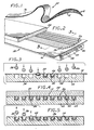
- a flat conductor cable assembly referred to generally by the reference numeral 10 has an elongated and generally flat configuration supporting in parallel array a plurality of generally coplanar round wire conductors 12. These round wire conductors 12 are supported within preformed channels between a lower ply 14 and an upper ply 16 of a polyimide insulation sheet material selected for resistance to degradation upon exposure to ultraviolet radiation and temperature extremes as encountered, for example, in an outer space environment.
- the flat conductor cable assembly or cable 10 advantageously provides a relatively thin and thus compact cable geometry for interconnecting components of electronic equipment, for example, as in a computer system or the like, with substantially minimum volumetric space requirements.
- the round wire conductors 12 are supported in spaced, electrically insulated relation by the lower and upper plies 14 and 16, which are advantageously formed from polyimide film or sheet material manufactured and sold by E. I. du Pont de Nemours and Company, Wilmington, Delaware, under the name Kapton.
- This Kapton film material is lightweight and possesses highly desirable pliability characteristics with excellent dielectric properties.
- Kapton film is highly resistant to degradation, such as embrittlement, when subjected to an outer space environment including relatively high exposure to ultraviolet radiation, exposure to temperature extremes, and prolonged exposure to vacuum.
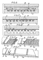
- the flat conductor cable 10 and a preferred process for the manufacture thereof are shown in more detail in Figures 2-8. More particularly, with specific reference to Figures 2-4, the lower ply 14 of the Kapton film material is initially preformed within a die assembly 18 to include a longitudinally elongated series of spaced parallel channel portions or channels 20 and land portions separating the channels, the channels being of open-topped configuration for subsequent reception of the round wire conductors 12, as will be described.
- This lower Kapton film ply is provided in lightweight sheet form having a thickness within the range of about 0.5 mil to about 5.0 mil, with a preferred sheet thickness being on the order of about 1.0 mil.
- the lower ply 14 is placed over an elongated forming die 22 having an upwardly presented face shaped to define a longitudinally elongated plurality of upwardly open aligned channels or grooves 24 shown in the illustrative drawings to have a generally rectangular cross-sectional shape, the channels being separated by land portions.
- the lower Kapton film ply 14 is pressed or otherwise drawn into conformance with the upper face of the forming die 22 whereby said lower ply 14 is preformed to include the elongated open-topped channels 20.
- conformance is achieved by placing elongated die bars 26 individually into the forming die grooves 24 to press the lower ply 14 into intimate seated relation within and following the contour of the grooves 24. As shown best in Figure 3, these die bars 26 are inserted one at a time in a regular or serial fashion by placing a subsequent die bar into a forming die groove 24 adjacent an already-inserted die bar to prevent significant stretching of the Kapton film material which could otherwise cause undesired film tearing.
- the die bars can be inserted into adjacent grooves beginning at the transverse center of the forming die and then proceeding outwardly on opposite sides thereof, as viewed in Figure 3, or the die bars can be placed into the grooves beginning at one side of the forming die.
- the lower Kapton film ply 14 has sufficient transverse width to span the width of the forming die 22 when pressed by the die bars 26 into conformance with the forming die grooves 24.
- the die assembly 18 is then subjected to a thermal forming step by appropriate exposure to an elevated temperature causing the lower ply to assume a thermal set in conformance with the geometry of the forming die face.
- the Kapton film ply having a thickness within the range of about 0.5 mil to about 5.0 mil will assume the desired thermal set when exposed to elevated temperature in the range of about 440°C (825°F) to about 510°C (950°F), and preferably within the range of about 454°C (850°F) to about 481°C (900°F), for at least about 30 minutes, with only light pressure maintaining the die assembly in a closed state being required. Exposure of a temperature above this range tends to cause undesired crystallization of the Kapton film, whereas exposure to a temperature below about 454° (850°F) fails to produce the desired thermal set.
- the thermal forming step is enhanced by constructing the die assembly 18 including the die bars 26 from a material having high thermal conductivity, such as aluminium, and further by shaping the die bars 26 for generally mating reception into the forming die grooves 24 to ensure intimate heat transfer contact with the lower film ply 14.
- these round wire conductors 12 are formed from a relatively soft braided wire of a material such as copper or aluminium wire having a high degree of flexibility and a diametric size generally corresponding with the depth of the channels 20.
- an adhesive substance is then placed over the lower Kapton film ply 14 and the conductors 12 seated within the preformed channels 20 ;
- one preferred adhesive substance comprises a relatively thin sheet of a thermal setting nitrile adhesive 30 having a size and shape generally corresponding with the length and width of the forming die 22.
- the upper Kapton film ply 16 which also has a length and width generally corresponding to the forming die 22, is then placed over the nitrile adhesive sheet 30 followed by reassembly of the upper platen 28 with the forming die 22 with sufficient pressure to maintain the lower and upper plies 14 and 16 in intimate contact with the adhesive sheet 30 which makes adhesive contact with the land portions of the ply 14.
- the thus-reassembled die assembly 18, as viewed in Figure 7, is ready for a thermal bonding step including a temperature sufficient to bond the plies 14 and 16 together via the adhesive sheet 30.
- a thermal forming step comprising exposure of the die assembly 18 to a temperature of about 176°C (350°F) for a time period of about 5 minutes is sufficient to provide a highly satisfactory thermal bond.
- the thus-formed flat conductor cable 10 having the round wire conductors 12 encased therein can then be stripped from the die assembly 18 by appropriate removal from the upper platen 28 and the lower forming die 22.
- the resultant conductor cable 10 cooperatively supports and insulates the conductors 12 separately within the channels 20 to permit independent transmission of electrical signals via said conductors.
- the Kapton film plies 14 and 16 are lightweight and possess a high degree of flexibility or pliability for versatile use in a wide variety of conductor cable environments.
- the conductor cable 10 is particularly suited to use in an outer space environment, since the Kapton film material is highly resistant to degradation from exposure to ultraviolet light or prolonged exposure to a vacuum. Moreover, the Kapton film material maintains its desired high pliability without embrittlement or ply separation throughout a wide range of temperature extremes typically encountered within an outer space environment.
- the overall length of the conductor cable 10 manufactured in accordance with the process depicted in Figures 2-8 is not limited to the longitudinal length of the forming die 22, nor is it necessary to physically splice adjacent ends of the round wire conductors 12 to provide a cable of increased overall length.
- the Kapton film plies encasing the conductors 12 can be installed in segments with misaligned, overlapping ends in association with continuous or uninterrupted conductors 12 to provide a conductor cable of virtually any desired overall length.
- round wire conductors 12 can be seated as described previously within preformed channels 20 of a lower Kapton film ply 14, wherein the round wire conductors 12 project substantially beyond the underlying aligned ends of the lower ply 14 and the forming die 22.
- the preformed lower ply 14 and the seated conductors 12 can then be covered by a suitable adhesive substance and an overlying upper Kapton film ply 16, followed by placement of the upper platen 28, generally as described above, but with the upper ply 16 and upper platen 28 terminating in longitudinal misalignment relative to the lower ply 14.
- a thermal bonding step as previously described can then be performed to provide a conductor cable segment with longitudinally misaligned lower and upper plies 14 and 16.
- the thus-formed cable segment is then positioned in end-to-end relation with an adjacent lower Kapton film ply 14' having preformed channels 20' and carried by an adjacent identical forming die 22 to permit seating of the conductors 12 within the aligned channels 20', as shown in Figure 10.
- a second upper ply 16' and associated adhesive substance are then placed in overlying relation with the exposed portions of the lower plies 14 and 14', as viewed in Figure 11, and this second upper ply 16' is covered by the upper platen 28 for performance of a subsequent thermal bonding step.
- An elongated conductor cable is thus formed having lower Kapton film plies 14 and 14' and upper film plies 16 and 16' disposed respectively in end-to-end relation but with the upper and lower ply ends longitudinally misaligned relative to each other.
- the conductor cable segments are thus interconnected in a secure and stable manner while permitting use of continuous round wire conductors 12 thereby permitting manufacture of a conductor cable of any desired length.
Landscapes
- Insulated Conductors (AREA)
Claims (15)
Applications Claiming Priority (2)
| Application Number | Priority Date | Filing Date | Title |
|---|---|---|---|
| US715697 | 1985-03-25 | ||
| US06/715,697 US4626298A (en) | 1985-03-25 | 1985-03-25 | Method of making flat multiple conductor cable |
Publications (2)
| Publication Number | Publication Date |
|---|---|
| EP0197624A1 EP0197624A1 (de) | 1986-10-15 |
| EP0197624B1 true EP0197624B1 (de) | 1990-09-12 |
Family
ID=24875118
Family Applications (1)
| Application Number | Title | Priority Date | Filing Date |
|---|---|---|---|
| EP86300439A Expired - Lifetime EP0197624B1 (de) | 1985-03-25 | 1986-01-22 | Leiterkabel |
Country Status (3)
| Country | Link |
|---|---|
| US (1) | US4626298A (de) |
| EP (1) | EP0197624B1 (de) |
| DE (1) | DE3674037D1 (de) |
Families Citing this family (19)
| Publication number | Priority date | Publication date | Assignee | Title |
|---|---|---|---|---|
| US5005611A (en) * | 1989-11-06 | 1991-04-09 | Hecker Jack D | Apparatus for modifying cables and products thereof |
| FR2661773B1 (fr) * | 1990-05-02 | 1995-03-31 | Cortaillod Cables Sa | Machine pour la fabrication d'une nappe de conducteurs isoles. |
| US5052105A (en) * | 1990-06-05 | 1991-10-01 | Hutchinson Technology, Inc. | Micro-cable interconnect |
| US5159154A (en) * | 1990-08-21 | 1992-10-27 | Thinking Machines Corporation | Multiple conductor dielectric cable assembly and method of manufacture |
| US5276759A (en) * | 1992-01-09 | 1994-01-04 | Raychem Corporation | Flat cable |
| US5268531A (en) * | 1992-03-06 | 1993-12-07 | Raychem Corporation | Flat cable |
| US5281765A (en) * | 1992-05-27 | 1994-01-25 | Sumitomo Wiring Systems, Ltd. | Wiring assembly for equipment and a method for producing the same |
| US5327513A (en) * | 1992-05-28 | 1994-07-05 | Raychem Corporation | Flat cable |
| US5502287A (en) * | 1993-03-10 | 1996-03-26 | Raychem Corporation | Multi-component cable assembly |
| DE10149889A1 (de) * | 2001-10-10 | 2003-05-08 | Ralf Wieduwilt | Niederspannungs-Verteilungssystem |
| JP4529374B2 (ja) * | 2002-10-23 | 2010-08-25 | ソニー株式会社 | データ伝送用ケーブル |
| US7183495B2 (en) * | 2004-03-29 | 2007-02-27 | Hirose Electric Co., Ltd. | Electrical connector |
| CH696344A5 (fr) * | 2006-02-22 | 2007-04-30 | Ses Soc En Solaire Sa | Film support et procédé de couplage de cellules photovoltaïques. |
| US20110061933A1 (en) * | 2009-09-11 | 2011-03-17 | Apple Inc. | Flat cable for use with an electronic device |
| US9263172B2 (en) * | 2011-02-17 | 2016-02-16 | Advanced Bionics Ag | Wire constructs |
| EP2678868B1 (de) | 2011-02-23 | 2019-05-01 | Miraco, Inc. | Schaltung für eine leitfähige tinte mit einstellbarem widerstand |
| CA2888508A1 (en) | 2012-10-25 | 2014-05-01 | Adc Telecommunications, Inc. | System and method for applying an adhesive coated cable to a surface |
| JP6037283B2 (ja) * | 2013-03-22 | 2016-12-07 | 矢崎総業株式会社 | ワイヤーハーネス用外装シートの取付け方法 |
| US11842829B2 (en) | 2022-03-21 | 2023-12-12 | International Business Machines Corporation | Flexible electrical cable with four copper layers |
Family Cites Families (10)
| Publication number | Priority date | Publication date | Assignee | Title |
|---|---|---|---|---|
| US2361374A (en) * | 1941-10-25 | 1944-10-31 | Charles W Abbott | Insulated conductor construction |
| US3082292A (en) * | 1957-09-30 | 1963-03-19 | Gore & Ass | Multiconductor wiring strip |
| GB1154027A (en) * | 1965-10-08 | 1969-06-04 | Gore & Ass | Positioning of Electrically Conductive Articles in Electrically Insulating Material |
| US3547718A (en) * | 1967-05-18 | 1970-12-15 | Rogers Corp | Method of making flat flexible electrical cables |
| US3900662A (en) * | 1973-01-17 | 1975-08-19 | Du Pont | Bondable adhesive coated polyimide film and laminates |
| US4090902A (en) * | 1973-05-23 | 1978-05-23 | Industrie Pirelli, S.P.A. | Optical fiber cable and manufacture thereof |
| US3833755A (en) * | 1973-08-16 | 1974-09-03 | Gore & Ass | Easily strippable ribbon cables |
| CA1035889A (en) * | 1973-10-13 | 1978-08-01 | Tsutomu Watanabe | Flexible adhesive composition and method for utilizing same |
| US4075420A (en) * | 1975-08-28 | 1978-02-21 | Burroughs Corporation | Cover layer for flexible circuits |
| US4375379A (en) * | 1978-11-09 | 1983-03-01 | Teltec, Inc. | Process of making a multiple conductor flexible wire cable |
-
1985
- 1985-03-25 US US06/715,697 patent/US4626298A/en not_active Expired - Fee Related
-
1986
- 1986-01-22 EP EP86300439A patent/EP0197624B1/de not_active Expired - Lifetime
- 1986-01-22 DE DE8686300439T patent/DE3674037D1/de not_active Expired - Fee Related
Also Published As
| Publication number | Publication date |
|---|---|
| DE3674037D1 (de) | 1990-10-18 |
| US4626298A (en) | 1986-12-02 |
| EP0197624A1 (de) | 1986-10-15 |
Similar Documents
| Publication | Publication Date | Title |
|---|---|---|
| EP0197624B1 (de) | Leiterkabel | |
| US4234759A (en) | Miniature coaxial cable assembly | |
| KR900007777B1 (ko) | 주름진 격막을 가진 케이블과 그 형성방법 | |
| CA1147822A (en) | Shielded flat cable | |
| US4375379A (en) | Process of making a multiple conductor flexible wire cable | |
| US4920234A (en) | Round cable having a corrugated septum | |
| US4443657A (en) | Ribbon cable with a two-layer insulation | |
| US4567321A (en) | Flexible flat cable | |
| US5142100A (en) | Transmission line with fluid-permeable jacket | |
| EP0627748B1 (de) | Flachkabel | |
| US3757029A (en) | Shielded flat cable | |
| US5360944A (en) | High impedance, strippable electrical cable | |
| US5993579A (en) | High performance electrical cable and method of manufacture | |
| US7628647B2 (en) | Coaxial cable and method for manufacturing the same | |
| JP2777650B2 (ja) | リボン形同軸ケーブル | |
| US4616717A (en) | Flexible wire cable and process of making same | |
| US7678998B2 (en) | Cable assembly | |
| EP0161065B1 (de) | Elektrische Übertragungsleitung | |
| US3522652A (en) | Method of making an electrical circuit assembly | |
| EP0073622A2 (de) | Mehrleiterkoaxialkabeleinheit | |
| CA1252162A (en) | Mass terminable flat cable | |
| US5051544A (en) | Transmission cable with reduced preparation time termination section | |
| EP0214276B1 (de) | Hochwertiges flachkabel | |
| EP0723275B1 (de) | Mehraderflachkabel | |
| EP0348954B1 (de) | Elektrische Verbindungsanordnung für Flachkabel |
Legal Events
| Date | Code | Title | Description |
|---|---|---|---|
| PUAI | Public reference made under article 153(3) epc to a published international application that has entered the european phase |
Free format text: ORIGINAL CODE: 0009012 |
|
| AK | Designated contracting states |
Kind code of ref document: A1 Designated state(s): DE FR GB IT NL |
|
| 17P | Request for examination filed |
Effective date: 19870317 |
|
| 17Q | First examination report despatched |
Effective date: 19880822 |
|
| ITF | It: translation for a ep patent filed | ||
| GRAA | (expected) grant |
Free format text: ORIGINAL CODE: 0009210 |
|
| AK | Designated contracting states |
Kind code of ref document: B1 Designated state(s): DE FR GB IT NL |
|
| REF | Corresponds to: |
Ref document number: 3674037 Country of ref document: DE Date of ref document: 19901018 |
|
| ET | Fr: translation filed | ||
| PLBE | No opposition filed within time limit |
Free format text: ORIGINAL CODE: 0009261 |
|
| STAA | Information on the status of an ep patent application or granted ep patent |
Free format text: STATUS: NO OPPOSITION FILED WITHIN TIME LIMIT |
|
| 26N | No opposition filed | ||
| ITTA | It: last paid annual fee | ||
| PGFP | Annual fee paid to national office [announced via postgrant information from national office to epo] |
Ref country code: GB Payment date: 19931220 Year of fee payment: 9 |
|
| PGFP | Annual fee paid to national office [announced via postgrant information from national office to epo] |
Ref country code: FR Payment date: 19940111 Year of fee payment: 9 |
|
| PGFP | Annual fee paid to national office [announced via postgrant information from national office to epo] |
Ref country code: DE Payment date: 19940127 Year of fee payment: 9 |
|
| PGFP | Annual fee paid to national office [announced via postgrant information from national office to epo] |
Ref country code: NL Payment date: 19940131 Year of fee payment: 9 |
|
| PG25 | Lapsed in a contracting state [announced via postgrant information from national office to epo] |
Ref country code: GB Effective date: 19950122 |
|
| PG25 | Lapsed in a contracting state [announced via postgrant information from national office to epo] |
Ref country code: NL Effective date: 19950801 |
|
| GBPC | Gb: european patent ceased through non-payment of renewal fee |
Effective date: 19950122 |
|
| PG25 | Lapsed in a contracting state [announced via postgrant information from national office to epo] |
Ref country code: FR Effective date: 19950929 |
|
| NLV4 | Nl: lapsed or anulled due to non-payment of the annual fee |
Effective date: 19950801 |
|
| PG25 | Lapsed in a contracting state [announced via postgrant information from national office to epo] |
Ref country code: DE Effective date: 19951003 |
|
| REG | Reference to a national code |
Ref country code: FR Ref legal event code: ST |
|
| PG25 | Lapsed in a contracting state [announced via postgrant information from national office to epo] |
Ref country code: IT Free format text: LAPSE BECAUSE OF NON-PAYMENT OF DUE FEES;WARNING: LAPSES OF ITALIAN PATENTS WITH EFFECTIVE DATE BEFORE 2007 MAY HAVE OCCURRED AT ANY TIME BEFORE 2007. THE CORRECT EFFECTIVE DATE MAY BE DIFFERENT FROM THE ONE RECORDED. Effective date: 20050122 |