EP0197172A1 - Device to obtain broken chips during the machining of work pieces - Google Patents
Device to obtain broken chips during the machining of work pieces Download PDFInfo
- Publication number
- EP0197172A1 EP0197172A1 EP85104285A EP85104285A EP0197172A1 EP 0197172 A1 EP0197172 A1 EP 0197172A1 EP 85104285 A EP85104285 A EP 85104285A EP 85104285 A EP85104285 A EP 85104285A EP 0197172 A1 EP0197172 A1 EP 0197172A1
- Authority
- EP
- European Patent Office
- Prior art keywords
- feed
- valve
- movement
- oscillating movement
- cylinder
- Prior art date
- Legal status (The legal status is an assumption and is not a legal conclusion. Google has not performed a legal analysis and makes no representation as to the accuracy of the status listed.)
- Granted
Links
Images


Classifications
-
- B—PERFORMING OPERATIONS; TRANSPORTING
- B23—MACHINE TOOLS; METAL-WORKING NOT OTHERWISE PROVIDED FOR
- B23B—TURNING; BORING
- B23B25/00—Accessories or auxiliary equipment for turning-machines
- B23B25/02—Arrangements for chip-breaking in turning-machines
-
- Y—GENERAL TAGGING OF NEW TECHNOLOGICAL DEVELOPMENTS; GENERAL TAGGING OF CROSS-SECTIONAL TECHNOLOGIES SPANNING OVER SEVERAL SECTIONS OF THE IPC; TECHNICAL SUBJECTS COVERED BY FORMER USPC CROSS-REFERENCE ART COLLECTIONS [XRACs] AND DIGESTS
- Y10—TECHNICAL SUBJECTS COVERED BY FORMER USPC
- Y10S—TECHNICAL SUBJECTS COVERED BY FORMER USPC CROSS-REFERENCE ART COLLECTIONS [XRACs] AND DIGESTS
- Y10S82/00—Turning
- Y10S82/904—Vibrating method or tool
-
- Y—GENERAL TAGGING OF NEW TECHNOLOGICAL DEVELOPMENTS; GENERAL TAGGING OF CROSS-SECTIONAL TECHNOLOGIES SPANNING OVER SEVERAL SECTIONS OF THE IPC; TECHNICAL SUBJECTS COVERED BY FORMER USPC CROSS-REFERENCE ART COLLECTIONS [XRACs] AND DIGESTS
- Y10—TECHNICAL SUBJECTS COVERED BY FORMER USPC
- Y10T—TECHNICAL SUBJECTS COVERED BY FORMER US CLASSIFICATION
- Y10T82/00—Turning
- Y10T82/14—Axial pattern
- Y10T82/141—Axial pattern having transverse tool and templet guide
- Y10T82/147—Axial pattern having transverse tool and templet guide having hydraulic actuator
-
- Y—GENERAL TAGGING OF NEW TECHNOLOGICAL DEVELOPMENTS; GENERAL TAGGING OF CROSS-SECTIONAL TECHNOLOGIES SPANNING OVER SEVERAL SECTIONS OF THE IPC; TECHNICAL SUBJECTS COVERED BY FORMER USPC CROSS-REFERENCE ART COLLECTIONS [XRACs] AND DIGESTS
- Y10—TECHNICAL SUBJECTS COVERED BY FORMER USPC
- Y10T—TECHNICAL SUBJECTS COVERED BY FORMER US CLASSIFICATION
- Y10T82/00—Turning
- Y10T82/18—Lathe for wheel or axle
-
- Y—GENERAL TAGGING OF NEW TECHNOLOGICAL DEVELOPMENTS; GENERAL TAGGING OF CROSS-SECTIONAL TECHNOLOGIES SPANNING OVER SEVERAL SECTIONS OF THE IPC; TECHNICAL SUBJECTS COVERED BY FORMER USPC CROSS-REFERENCE ART COLLECTIONS [XRACs] AND DIGESTS
- Y10—TECHNICAL SUBJECTS COVERED BY FORMER USPC
- Y10T—TECHNICAL SUBJECTS COVERED BY FORMER US CLASSIFICATION
- Y10T82/00—Turning
- Y10T82/25—Lathe
- Y10T82/2502—Lathe with program control
-
- Y—GENERAL TAGGING OF NEW TECHNOLOGICAL DEVELOPMENTS; GENERAL TAGGING OF CROSS-SECTIONAL TECHNOLOGIES SPANNING OVER SEVERAL SECTIONS OF THE IPC; TECHNICAL SUBJECTS COVERED BY FORMER USPC CROSS-REFERENCE ART COLLECTIONS [XRACs] AND DIGESTS
- Y10—TECHNICAL SUBJECTS COVERED BY FORMER USPC
- Y10T—TECHNICAL SUBJECTS COVERED BY FORMER US CLASSIFICATION
- Y10T82/00—Turning
- Y10T82/25—Lathe
- Y10T82/2531—Carriage feed
- Y10T82/2533—Control
-
- Y—GENERAL TAGGING OF NEW TECHNOLOGICAL DEVELOPMENTS; GENERAL TAGGING OF CROSS-SECTIONAL TECHNOLOGIES SPANNING OVER SEVERAL SECTIONS OF THE IPC; TECHNICAL SUBJECTS COVERED BY FORMER USPC CROSS-REFERENCE ART COLLECTIONS [XRACs] AND DIGESTS
- Y10—TECHNICAL SUBJECTS COVERED BY FORMER USPC
- Y10T—TECHNICAL SUBJECTS COVERED BY FORMER US CLASSIFICATION
- Y10T82/00—Turning
- Y10T82/25—Lathe
- Y10T82/2531—Carriage feed
- Y10T82/2541—Slide rest
Definitions
- means for detecting the speed of a main spindle are provided, which are linked or connectable to the means for setting the frequency of the oscillating movement such that a change in the speed of the main spindle is a proportional change in the Fre effect of the swinging movement.
- a change in the speed of the main spindle is a proportional change in the Fre effect of the swinging movement.
- the signal of the positive and negative half-wave can be amplified as desired via a downstream amplifier 143 without changing the size relationships of the two signals to one another. Positive and negative half-waves are supplied to the control electronics 144 of the valve.
- the scales 183, 184 are shifted by magnetic coils 189, 190.
Abstract
Die Erfindung betrifft ein Verfahren zur Erzeugung von Bruchspänen bei der Drehbearbeitung von Werkstücken mittels einer sich im Verlauf der Werkstückumdrehung verändernden Vorschubgeschwindigkeit des Drehwerkzeuges. Bei einer bekannten Verfahrensweise dieser Art konnte ein zuverlässiger Spanbruch micht erreicht werden und es war insbesondere nur möglich geradlinige Werkstückkonturen zu erzeugen. Mit der Erfindung soll ein zuverlässiger Spanbruch erreicht werden, auch bei der Bearbeitung von Werkstücken mit nicht geradlinigen Konturen. Dies wird dadurch erreicht, daß das werkzeug entlang der Linie der Vorschubvektoren periodisch schwingt, wobei die Schwingungsamplitude etwa dem halben effektiven Vorschubweg pro Umdrehung entspricht und die Wellenlänge der Amplitude so bemessen ist, daß sie selbst oder ihr ganzzahliges Vielfaches zuzüglich einer halben Wellenlänge stets gleich ist dem jeweiligen momentanen Werkstücksumfang durch den betrachteten Arbeitspunkt.The invention relates to a method for producing broken chips during the turning of workpieces by means of a feed speed of the turning tool that changes in the course of the workpiece rotation. With a known procedure of this type, a reliable chip break could not be achieved and it was in particular only possible to produce rectilinear workpiece contours. With the invention, a reliable chip break is to be achieved, even when machining workpieces with non-linear contours. This is achieved in that the tool periodically oscillates along the line of the feed vectors, the vibration amplitude corresponding to approximately half the effective feed path per revolution and the wavelength of the amplitude being such that it itself or its integral multiple plus half a wavelength is always the same the respective current workpiece circumference through the considered working point.
Description
Die Erfindung betrifft ein Verfahren zur Erzeugung von Bruchspänen bei der Drehbearbeitung von Werkstücken mittels einer sich im Verlauf der WerkstUckumdrehung verändernden Vorschubgeschwindigkeit des Drehwerkzeuges, so wie eine Einrichtung zur Durchführung des Verfahrens. Ein solches Verfahren und eine dazu geeignete Einrichtung sind bereits bekannt geworden mit der DE-OS 22 33 229. Es zeigt sich jedoch, daß dieses Verfahren nicht geeignet ist, einen sicheren Spanbruch zu gewährleisten. Vielmehr kommt es während der Drehbearbeitung in periodischem Wechsel zu kurzbrechenden Spänen und dann über längere Zeit wieder zu nicht kurz brechenden Spänen mit unterschiedlichen Spandicken. Darüber hinaus ist dieses Verfahren auch nur für eine geradlinige Bearbeitung eines Werkstücks anwendbar und auch die offenbarte Vorrichtung läßt eine andere Werkzeugbewegung nicht zu.The invention relates to a method for producing chips during the turning of workpieces by means of a feed speed of the turning tool which changes in the course of the workpiece rotation, and to a device for carrying out the method. Such a method and a suitable device have already been disclosed in DE-OS 22 33 229. However, it has been shown that this method is not suitable for ensuring safe chip breakage. Rather, short-breaking chips occur periodically during turning and then chips with different chip thicknesses that do not break briefly over a longer period of time. In addition, this method can only be used for straight-line machining of a workpiece, and the device disclosed does not permit any other tool movement.
Dem gegenüber liegt der Erfindung die Aufgabe zugrunde, ein Verfahren und eine Vorrichtung der eingangs beschriebenen Art vorzuschlagen, zur Ermöglichung eines zuverlässigen kurzen Spanbruchs, besonders bei der Drehbarbeitung von Werkstücken sehr großen Durchmessers, wobei die Länge der Spanbruchstücke vorherbestimmbar sein soll und wobei auch nicht geradlinige Konturen bearbeitbar sein sollen.In contrast, the invention is based on the object of proposing a method and a device of the type described at the outset to enable reliable short chip breaking, especially when machining workpieces of very large diameter, the length of the chip fragments being intended to be predeterminable and also not being straight-line Contours should be editable.
Diese Aufgabe ist hinsichtlich des notwendigen Verfahrens dadurch gelöst, daß das Werkzeug entlang der Linie der Vorschubvektoren schwingt, wobei die Schwingungsamplitude etwa dem halben effektiven Vorschubweg pro Umdrehung entspricht und die Wellenlänge der Amplitude so bemessen ist, daß sie selbst oder ihr ganzzahliges Vielfaches zuzüglich einer halben Wellenlänge stets gleich ist dem jeweiligen momentanen WerkstUckumfang durch den betrachteten Arbeitspunkt. Es ist also festzustellen, daß die an sich bekannte Schwingbewegung des Drehwerkzeuges nicht mehr unbedingt eine Schwingbewegung auf gerader Linie sein muß, sondern es soll das Werkzeug den Vorschubvektoren bei der Schwingbewegung folgen, so daß also die Schwingbewegung ggf. auch entlang einer gekrümmten Linie erfolgen kann. Es soll also die Schwingbewegung nicht grundsätzlich geradlinig erfolgen, sondern das Werkzeug soll immer entlang der herzustellenden Kontur schwingen. Hierbei ist es wichtig, daß die Schwingungsamplitude etwa dem halben effektiven Vorschubweg, den das Werkzeug pro Umdrehung des Werkstückes zurücklegt, entspricht. Hierbei ist der effektive Vorschubweg der Vorschubweg, den das Werkzeug entlang der herzustellenden Kontur zurücklegt. Zur Erzielung des gewünschten Spanbruches ist nunmehr besonders wichtig die Wellenlänge der Schwingung des Werkzeuges, denn diese muß so bemessen sein,-daß sie selbst oder ihr ganzzahliges Vielfaches ergänzt um die Hälfte der Wellenlänge der Schwingung den Umfang ergibt, den der betrachtete Arbeitspunkt des Werkzeuges am Werkstück bei einer Umdrehung des Werkstückes beschreibt. Hierdurch ist sichergestellt, daß durch die entsprechende Schwingbewegung des Werkzeuges immer die Minima und Maxima der durch die Schwingung erzeugten Werkstückkontur so zusammentreffen, daß in Vorschubrichtung gesehen auf ein Wellental des vorangegangenen Schnittes stets ein Wellenberg des nachfolgenden Schnittes folgt, so daß an diesem Punkt die Spandicke mindestens angenähert zu Null wird und der Span bricht. Die Spanbrechung erfolgt mit absoluter Zuverlässigkeit und ist nicht von irgendeiner Zufallskonstellation am Werkstück abhängig. Die Spanlänge ist hierbei Uber die Wellenlänge der Schwingung vorherbestimmbar.This object is achieved with respect to the necessary method in that the tool along the Line of the feed vectors oscillates, the oscillation amplitude corresponding to approximately half the effective feed path per revolution and the wavelength of the amplitude is dimensioned such that it itself or its integral multiple plus half a wavelength is always the same as the respective current workpiece volume through the working point under consideration. It should therefore be noted that the known oscillating movement of the rotary tool no longer necessarily has to be an oscillating movement on a straight line, but the tool should follow the feed vectors during the oscillating movement, so that the oscillating movement can also take place along a curved line . The oscillating movement should therefore not always take place in a straight line, but the tool should always oscillate along the contour to be produced. It is important here that the oscillation amplitude corresponds to approximately half the effective feed path that the tool covers per revolution of the workpiece. The effective feed path is the feed path that the tool travels along the contour to be produced. To achieve the desired chip break, the wavelength of the vibration of the tool is now particularly important, because it must be dimensioned so that it itself or its integer multiple adds half the wavelength of the vibration to the extent that the considered working point of the tool on Describes the workpiece during one revolution of the workpiece. This ensures that the minima and maxima of the workpiece contour generated by the vibration always meet through the corresponding oscillating movement of the tool in such a way that seen in the direction of advance onto a trough of the previous one Cut always follows a wave crest of the following cut, so that at this point the chip thickness becomes at least approximately zero and the chip breaks. Chip breaking takes place with absolute reliability and is not dependent on any random constellation on the workpiece. The span length can be predetermined using the wavelength of the vibration.
Eine Einrichtung zur Durchführung des Verfahrens kann eine Dreheinrichtung mit einem Support sein, mit mindestens einem angetriebenen Längs- und Querschlitten zur Bewegung des Drehwerkzeuges, deren Antriebe von einer Steuereinrichtung gesteuert werden. Hierbei soll der Begriff "Support" nicht nur solche Einrichtungen umfassen, bei denen die Schlittenbewegung von einer zu kopierenden Schablone gesteuert wird, sondern vielmehr auch solche Einrichtungen, bei denen die Bewegung beispielsweise numerisch gesteuert nach einem vorgegebenen Programm erfolgt, so daß hier sozusagen das Bewegungsprogramm des steuernden Rechners kopiert wird.A device for carrying out the method can be a rotating device with a support, with at least one driven longitudinal and transverse slide for moving the turning tool, the drives of which are controlled by a control device. Here, the term "support" is intended not only to include those devices in which the carriage movement is controlled by a template to be copied, but rather also those devices in which the movement is, for example, numerically controlled according to a predetermined program, so that here, so to speak, the movement program of the controlling computer is copied.
Zur Durchführung des erfindungsgemäßen Verfahrens ist eine solche Einrichtung dadurch gekennzeichnet, daß Mittel zur Erzeugung einer periodischen Schwingbewegung vorgesehen sind, die derart mit der Steuereinrichtung zusammenwirken, daß die erzeugte Schwingbewegung an jedem Punkt entlang der Bearbeitungskontur erfolgt, wobei. weiter Mittel zur Einstellung der Amplitude und der Frequenz der Schwingbewegung vorgesehen sind. Mittel zur Erzeugung einer periodischen Schwingbewegung sind im Stand der Technik an sich bekannt, wie auch die eingangs beschriebene Schrift zeigt. Es ist nun noch erforderlich, dafür zu sorgen, daß diese Schwingbewegung immer in Richtung der zu erzeugenden Kontur erfolgt. Hierzu ist es erforderlich, daß das die Schwingbewegung erzeugende Bauelement mit der Steuerung zusammenarbeitet, so daß die Steuerung veranlaßt wird, ihre Bewegung zur Erzeugung der gewünschten Schwingbewegung in beide Richtungen pendelnd auszuführen. Hierzu ist lediglich eine der Bauart der Steuerung entsprechende Umsteuerung der Organe, die die Bewegung erzeugen, erforderlich. Weiterhin ist es erforderlich Amplitude und Frequenz der Schwingbewegung festzulegen und ggfls. einzustellen. Die Größe der Amplitude ist hierbei abhängig von dem zu überlagernden Vorschub, wobei die Schwingfrequenz des Werkzeuges so abzustimmen ist, daß die Lehre des Verfahrens nach Anspruch 1, wie eben beschrieben, erreicht wird. Die Frequenz muß also so bemessen sein, daß an irgendeinem Arbeitspunkt in Umfangsrichtung des Werkstückes betrachtet, der durch eine Kreisbewegung dieses Punktes entstehende Umfang einem ganzzahligen Vielfachen der durch die Frequenz entstehenden Wellenlänge zuzüglich einer halben Wellenlänge entspricht. Um dies zu erreichen muß die Frequenz in Relation zur Drehzahl des Werkstückes eingestellt werden.In order to carry out the method according to the invention, such a device is characterized in that means for generating a periodic oscillating movement are provided, which cooperate with the control device in such a way that the generated oscillating movement takes place at every point along the machining contour, whereby. further means for adjusting the amplitude and the frequency of the oscillating movement are provided. Means for generating a periodic oscillating movement are known per se in the prior art, such as the font described at the beginning also shows. It is now necessary to ensure that this oscillating movement always takes place in the direction of the contour to be generated. For this purpose, it is necessary that the component generating the oscillating movement cooperate with the control unit, so that the control unit is caused to oscillate in both directions in order to generate the desired oscillating movement. All that is required is a reversal of the organs that generate the movement, corresponding to the type of control. Furthermore, it is necessary to determine the amplitude and frequency of the oscillating movement and if necessary. adjust. The size of the amplitude is dependent on the feed to be superimposed, the oscillation frequency of the tool being adjusted so that the teaching of the method according to claim 1, as just described, is achieved. The frequency must therefore be such that viewed at any working point in the circumferential direction of the workpiece, the circumference resulting from a circular movement of this point corresponds to an integral multiple of the wavelength caused by the frequency plus half a wavelength. To achieve this, the frequency must be set in relation to the speed of the workpiece.
Es ist daher nach einer Ausgestaltung der erfindungsgemäßen Einrichtung noch vorgeschlagen, daß Mittel zur Erfassung der Drehzahl einer Hauptspindel vorgesehen sind, die derart mit den Mitteln zur Einstellung der Frequenz der Schwingbewegung verknüpft oder verknUpfbar sind, daß eine Veränderung der Drehzahl der Hauptspindel eine proportionale Veränderung der Frequenz der Schwingbewegung bewirkt. Auf diese Art wird es möglich, die einmal eingestellte Relation zwischen Frequenz und Drehzahl auch bei veränderten Drehzahlen, beispielsweise zur Veränderung von Schnittgeschwindigkeiten, beizubehalten, so daß eine neuerliche Einstellung entfallen kann.It is therefore proposed according to an embodiment of the device according to the invention that means for detecting the speed of a main spindle are provided, which are linked or connectable to the means for setting the frequency of the oscillating movement such that a change in the speed of the main spindle is a proportional change in the Fre effect of the swinging movement. In this way it becomes possible to maintain the once set relation between frequency and speed even at changing speeds, for example for changing cutting speeds, so that a new setting can be omitted.
In weiterer Ausgestaltung der erfindungsgemäßen Einrichtung ist noch vorgesehen, daß die Mittel zur Erzeugung der Schwingbewegung in Abhängigkeit von der Drehzahl der Hauptspindel zwangsgesteuert sind, wobei die Frequenz der Schwingbewegung als Schwingung pro Hauptspindelumdrehung einstellbar ist. Ohne eine solche Zwangssteuerung ist es möglich, daß sich geringfügigste Einstellungsfehler in der Relation zwischen Frequenz und Drehzahl im Laufe vieler Umdrehungen der Hauptspindel aufaddieren, so daß bei den Schwingungen des Werkzeuges eine unerwünschte Phasenverschiebung eintritt derart, daß ein Spanbruch über längere Zeit nicht erfolgt, wobei später wieder Spanbruch eintritt, wenn die Phasenverschiebung genügend groß geworden ist um wieder die Ausgangssituation herzustellen. Die beschriebene Zwangssteuerung macht daher eine hochpräzise Einstellung der Relation von Frequenz und Drehzahl überflüssig.In a further embodiment of the device according to the invention, it is also provided that the means for generating the oscillating movement are positively controlled as a function of the rotational speed of the main spindle, the frequency of the oscillating movement being adjustable as oscillation per main spindle revolution. Without such positive control, it is possible that the slightest setting errors in the relationship between frequency and speed add up over many revolutions of the main spindle, so that an undesirable phase shift occurs in the vibrations of the tool in such a way that chip breakage does not occur over a long period of time Chip breakage occurs again later when the phase shift has become sufficiently large to restore the starting situation. The described positive control therefore makes highly precise setting of the relationship between frequency and speed superfluous.
Eine weitere Ausgestaltung der Erfindung sieht vor, daß eine die Drehzahl und den Drehwinkel der Hauptspindel erfassende Signaleinrichtung vorgesehen ist, die in Abhängigkeit von Drehzahl und Drehwinkel der Hauptspindel Steuerimpulse an die Mittel zur Erzeugung der Schwingbewegung abgibt, wobei die über eine Umdrehung der Hauptspindel anfallenden Steuerimpulse an der Signaleinrichtung so aufteilbar sind, daß hierdurch die Mittel zur Erzeugung der Schwingbewegung (2n+1) Halbschwingungen durchführen, wobei "n" eine ganze Zahl ist. Dies ist eine einfache Möglichkeit der Zwangssteuerung, bei der gleichzeitig und auf einfache Art und Weise eine Überlagerung des notwendigen Vorschubweges möglich wird.A further embodiment of the invention provides that a signal device is provided which detects the speed and the angle of rotation of the main spindle and which, as a function of the speed and angle of rotation of the main spindle, emits control pulses to the means for generating the oscillating movement, the control pulses occurring over one revolution of the main spindle are so divisible on the signaling device that hereby carry out the means for generating the oscillating movement (2n + 1) half-oscillations, "n" being an integer. This is a simple possibility of positive control, in which at the same time and in a simple manner an overlay of the necessary feed path is possible.
Eine weitere Ausgestaltung der Erfindung bezogen auf einen CNC-gesteuerten Support, bei dem jeder Schlitten mit einem Wegmeßsystem zusammenarbeitet, das mindestens je aus einem Maßstab und einem dem Maßstab zugeordneten Reiter zur Wegabfrage am Maßstab besteht wird darin gesehen, daß Mittel zur Erzeugung einer alternierenden Relativbewegung zwischen Maßstab und Reiter vorgesehen sind, wobei die Mittel mindestens über einen Frequenzgenerator miteinander koordiniert sind. Hierdurch gelingt es, die gewünschte koordinierte Schwingbewegung auch bei CNC-gesteuerten Schlitten zu erzeugen, ohne daß hierfür nennenswert größere Rechner- und Speicherkapazitäten notwendig wären.A further embodiment of the invention based on a CNC-controlled support, in which each slide works together with a path measuring system, which at least each consists of a scale and a tab assigned to the scale for querying the path on the scale, is seen in the fact that means for generating an alternating relative movement are provided between the scale and tab, the means being coordinated with one another at least via a frequency generator. In this way, it is possible to generate the desired coordinated oscillating movement even in the case of CNC-controlled slides, without the need for appreciably larger computer and storage capacities.
Eine ergänzende Ausgestaltung der Erfindung sieht vor, daß die Mittel zur Erzeugung der alternierenden Relativbewegung als Magnetspulen mit entsprechenden Ankern ausgebildet sind. Hierdurch wird ein in Frequenz und Amplitude leicht steuerbarer Antrieb erreicht. Natürlich können diese Mittel auch aus anderen Antriebseinrichtungen, wie z. B. einem Fluidzylinder als die Verschiebung bewirkendes Mittel bestehen. Die Relativbewegung könnte auch über eine Gewindespindel, die hin- und hergedreht wird durch einen Antrieb erreicht werden. Auch weitere Möglichkeiten sind denkbar.A supplementary embodiment of the invention provides that the means for generating the alternating relative movement are designed as magnetic coils with corresponding armatures. This achieves a drive that is easily controllable in frequency and amplitude. Of course, these means can also come from other drive devices, such as. B. a fluid cylinder as the displacement effecting means. The relative movement could also be achieved via a threaded spindle that is rotated back and forth by a drive. Other options are also conceivable.
Eine weitere Ausgestaltung der Erfindung sieht vor, daß das über die Magnetspulen bewegte Teil das Wegmeßsystem in stromlosem Zustand der Magnetspule in Mittelstellung zentriert ist, wobei die Mittelstellung die Bezugsstellung für die Weginformation der CNC-Steuerung bildet. Hierdurch wird in einfacher Weise die Null-Position der Schlitten bestimmbar.A further embodiment of the invention provides that the part moved over the magnet coils is centered in the middle position in the de-energized state of the magnet coil, the middle position forming the reference position for the path information of the CNC control. In this way, the zero position of the carriage can be determined in a simple manner.
In ergänzender Ausgestaltung ist schließlich noch vorgesehen, daß zwischen Frequenzgenerator und Magnetspulen eine Einrichtung zur Aufteilung des vom Frequenzgenerator ankommenden Signals auf die Magnetspulen vorgesehen ist, wobei die Aufteilung in Abhängigkeit vom Steigungswinkel, vorzugsweise vom augenbliklichen Steigungswinkel, des herzustellenden Profils erfolgt. Hierdurch gelingt es mit einfachen Mitteln der zu erzeugenden Kontur auch während der Schwingbewegung mit ausreichender Genauigkeit zu folgen.In a supplementary embodiment, it is finally provided that a device is provided between the frequency generator and the magnetic coils for distributing the signal arriving from the frequency generator to the magnetic coils, the division taking place as a function of the pitch angle, preferably the instantaneous pitch angle, of the profile to be produced. As a result, it is possible to follow the contour to be generated with sufficient accuracy with simple means even during the oscillating movement.
Eine weitere Ausgestaltung der Erfindung bezogen auf einen hydraulisch gesteuerten Kopiersupport, bei dem mittels eines fühlergesteuerten Kopierventils ein den Geschwindigkeitsvektor des Drehwerkzeuges bestimmender und regelbarer Druckölstrom auf je eine den Längsschlitten und den Planschlitten antreibende Kolben-Zylinder-Einheit aufgeteilt wird sieht vor, daß eine Schalttrommel vorgesehen ist, die mit der Hauptspindel in Antriebsverbindung steht in einer solchen Übersetzung, daß pro Schwingung des Werkzeuges eine Umdrehung der Schalttrommel erfolgt, wobei die Schalttrommel mindestens zwei Nockenbahnen mit Nocken aufweist, von denen zugeordnete Schalter betätigt werden, wovon über die zugeordneten Schalter die eine Nockenbahn das Signal "Vorschub vor" und die andere Nockenbahn "Vorschub zurück" abgiebt, wobei das Signal "vor" etwa den (1 + 1/n)-fachen Wert des Grundvorschubes und das Signal "zurück" etwa den (1 - 1/n)-fachen Wert des Grundvorschubes an der Einrichtung zur Erzeugung der Schwingbewegung ansteht. Dies ist eine besonders einfache Art insbesondere bei fühlergesteuerten Kopiersupporten hydraulischer Bauart die gewünschte Schwingbewegung und Vorschubbewegung zu erzeugen und zu steuern. Die Antriebsverbindung zwischen Schalttrommel und Hauptspindel sorgt hierbei dafür, daß ein Phasenfehler zwischen Frequenz und Drehzahl der Hauptspindel nicht auftre.ten kann.A further embodiment of the invention relates to a hydraulically controlled copy support, in which, by means of a sensor-controlled copy valve, a pressure oil flow that determines and regulates the speed vector of the turning tool is divided into a piston-cylinder unit that drives the longitudinal slide and the cross slide provides that a switching drum is provided is which is in drive connection with the main spindle in such a ratio that one rotation of the switching drum takes place per oscillation of the tool, the switching drum having at least two cam tracks with cams, of which actuated assigned switches of which via the assigned switches one cam track emits the signal "feed forward" and the other cam track "feed back", the signal "forward" approximately (1 + 1 / n) times the value of the basic feed and the signal " back "about (1 - 1 / n) times the value of the basic feed at the device for generating the oscillating movement. This is a particularly simple way of generating and controlling the desired oscillating movement and feed movement, particularly in the case of sensor-controlled copy supports of hydraulic design. The drive connection between the switching drum and the main spindle ensures that a phase error between the frequency and speed of the main spindle cannot occur.
Eine ergänzende Ausgestaltung der Erfindung sieht vor, daß in der Antriebsverbindung von Hauptspindel und Schalttrommel ein Schaltgetriebe vorgesehen ist. Hierdurch gelingt es, die Schalttrommel bei gleicher Drehzahl der Hauptspindel mit unterschiedlichen Drehzahlen anzutreiben und hierdurch die Schwingfrequenz des Werkzeuges zu ändern.A supplementary embodiment of the invention provides that a manual transmission is provided in the drive connection of the main spindle and the shift drum. This makes it possible to drive the shift drum at the same speed of the main spindle at different speeds and thereby to change the oscillation frequency of the tool.
Eine weitere Ausgestaltung der Erfindung sieht für den Fall, daß die Kolben-Zylinder-Einheit für die Planbewegung in der einen Zylinderkammer direkt mit einer Druckquelle und in der anderen Zylinderkammer über ein Fühlerventil mit der Druckquelle verbunden ist und wobei die Kolben-Zylinder-Einheit für die Längsbewegung in der einen Zylinderkammer direkt mit der Druckquelle und in der anderen Zylinderkammer mit dem Tank verbunden ist, vor, daß die Verbindungsleitungen der Kolben-Zylinder-Einheit für die Längsbewegung durch eine Einrichtung zum Sperren und Vertauschen der Ölströme gefUhrt sind, wobei die Tankleitung durch ein druckgesteuertes Sperrventil geführt ist, dessen Steuerleitung direkt mit der Druckquelle verbunden ist. Durch die in der beschriebenen Weise zwischengeschaltete Einrichtung zum Sperren und Vertauschen der Ölströme gelingt es in Verbindung mit dem beschriebenen druckgesteuerten Sperrventil auf einfachste Art und Weise die die Kopierbewegung erzeugenden Kolben-Zylinder-Einheiten jeweils durch Umsteuerung in Schwingbewegung zu versetzen, wobei diese Schwingbewegung wegen der Aufteilung des Ölstroms durch das KopierfUhlerventil auf die beiden Kolben-Zylinder-Einheiten immer entlang der zu kopierenden Linie erfolgt. Dreheinrichtungen mit den beschriebenen Kopiersteuerungen sind weit verbreitet im Einsatz. Mit der hier beschriebenen Ausgestaltung lassen sich solche bereits bestehenden Kopiersteuerungen auf einfachste Art und Weise so umrüsten, daß das Werkzeug die gewünschte Schwingbewegung zusammen mit dem notwenigen Vorschub durchführt.A further embodiment of the invention provides for the case that the piston-cylinder unit for the plane movement in one cylinder chamber is connected directly to a pressure source and in the other cylinder chamber via a sensor valve to the pressure source, and the piston-cylinder unit for the longitudinal movement in one cylinder chamber is directly connected to the pressure source and in the other cylinder chamber to the tank, before that the connecting lines of the piston-cylinder unit for the longitudinal movement by a device for locking and interchanging the Oil flows are guided, the tank line being guided through a pressure-controlled shut-off valve, the control line of which is connected directly to the pressure source. Due to the interposed device for blocking and interchanging the oil flows in connection with the described pressure-controlled shut-off valve, the piston-cylinder units generating the copying movement can be set into oscillating movement by reversing, this oscillating movement due to the Distribution of the oil flow through the copy sensor valve to the two piston-cylinder units always takes place along the line to be copied. Rotary devices with the described copying controls are widely used. With the configuration described here, such existing copying controls can be converted in a very simple manner in such a way that the tool performs the desired oscillating movement together with the necessary feed.
In ergänzender Ausgestaltung ist schließlich noch vorgesehen, daß die Einrichtung zum Sperren und Vertauschen der Ölströme als Vierwegedreistellungsschieberventilausgebildet ist. Dies ist ein handelsübliches Bauelement, dessen einfacher Einsatz das angestrebte Ziel besonders leicht und kostengünstig erreichen läßt.In a supplementary embodiment it is finally provided that the device for blocking and exchanging the oil flows is designed as a four-way three-position slide valve. This is a commercially available component, the simple use of which allows the desired goal to be achieved particularly easily and inexpensively.
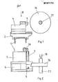
Das erfindungsgemäße Verfahren soll nunmehr beispielhaft anhand der Zeichnungen näher erläutert werden. Hierbei wird in den Zeichnungen als Beispiel für eine erfindungsgemäße Einrichtung ausgegangen von einem Kopiersupport einer Radsatzdrehmaschine.The method according to the invention will now be explained in more detail by way of example with reference to the drawings. In the drawings, as an example of a device according to the invention, a copy support of a wheelset lathe is assumed.
- Es zeigen: Figur 1 Seitenansicht eines KopiersupportesFIG. 1 shows a side view of a copy support
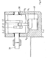
- Figur 2 Ansicht des Supports in Richtung B der Figur 1FIG. 2 view of the support in direction B of FIG. 1
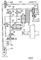
- Figur 3 Hydraulikschaltplan des SupportesFigure 3 Hydraulic circuit diagram of the support
- Figur 4, 4a Vergrößerte Darstellung einer Vorschubrille für kontinuierlichen Vorschub und einer Vorschubrille eines Schwingvorschubes einer Schwingung nach der ErfindungFigure 4, 4a enlarged view of a feed groove for continuous feed and a feed groove of a vibratory feed of a vibration according to the invention
- Figur 5 Vorschubbild bei unterschiedlicher Anzahl der Schwingungsperioden pro Werkstückumdrehung schematischFigure 5 schematic diagram with different number of oscillation periods per workpiece revolution
- Figur 6 Schalttrommel im Schnitt gemäß Linie II-II nach Figur 7Figure 6 shift drum in section along line II-II of Figure 7
- Figur 7 Schalttrommel im Schnitt gemäß Linie I-I der Figur 6Figure 7 shift drum in section along line I-I of Figure 6
- Figur 8 Abwicklung des SchalttrommelumfangsFigure 8 processing of the switching drum circumference
- Figur 9 Antriebsschema der SchalttrommelFigure 9 drive diagram of the shift drum
- Figur 10 HydraulikschaltplanFigure 10 Hydraulic circuit diagram
- Figur 11 Elektrische Steuerung für die Schwingbewegung und den kontinuierlichen VorschubFigure 11 Electrical control for the swinging motion and the continuous feed
- Figur 12 Elektrische Kopiersteuerung fUr normalen VorschubbetriebFigure 12 Electrical copy control for normal feed operation
- Figur 13 Elektrische Kopiersteuerung für SchwingvorschubFigure 13 Electric copy control for vibratory feed
- Figur 14 KopiersteuerungFigure 14 Copy control
- Figur 15 GeschwindigkeitsdiagrammFigure 15 speed diagram
- Figur 16 KopiersteuerungFigure 16 Copy control
- Figur 17 SchablonenprofilFigure 17 stencil profile
- Figur 18 Schema einer elektronischen SteuerungFigure 18 Scheme of an electronic control
- Figur 19 Diagramm eines SteuersingnalsFigure 19 Diagram of a control signal
- Figur 19' Ventilkolben schematischFigure 19 'valve piston schematically
- Figur 20 CNC-SteuerungFigure 20 CNC control
- Figur 21 BewegungsdiagrammFigure 21 Motion diagram
- Figur 22 BewegungsdiagrammFigure 22 Motion diagram
Die Figur 1 zeigt in schematisierter Darstellung einen möglichen Aufbau eines hydraulisch gesteuerten Kopiersupportes einer Radsatzdrehbank in Seitenansicht. Figur 2 zeigt diese Anordnung in Draufsicht, also in Richtung des Pfeiles B nach Figur 1.Figure 1 shows a schematic representation of a possible structure of a hydraulically controlled copy support of a wheelset lathe in side view. Figure 2 shows this arrangement in plan view, that is in the direction of arrow B of Figure 1.
Auf den Längsführungen 1 eines nicht weiter dargestellten Maschinenbettes gleitet ein Längsschlitten 2, der über eine Kolben-Zylinder-Einheit 3 verschoben werden kann. Auf dem Längsschlitten 2 ist in an sich bekannter Anordnung ein Planschlitten 4 angeordnet, der winklig zur Verschieberichtung des Längsschlittens, vorzugsweise rechtwinklig, auf dem Längsschlitten ebenfalls von einer Kolben-Zylinder-Einheit, die jedoch nicht näher dargestellt ist, verschoben werden kann. Der Planschlitten 4 trägt hierbei das Werkzeug 5.A
Kopierschlitten des oben beschriebenen grundsätzlichen Aufbaues sind bekannt, so daß es einer detaillierteren Beschreibung nicht bedarf. Hierbei können Kopierschlitten dieses Aufbaus auch so konstruiert sein, daß der Längsschlitten 2 nicht unmittelbar auf den Längsführungen des Bettes angeordnet ist, sondern vielmehr auf einem weiteren Zwischenschlitten, der den Längsschlitten trägt und der seinerseits auf den LängsfUhrungen 1 des Maschinenbettes verschiebbar und feststellbar geführt ist, wobei dann natürlich das Widerlager 79 für die Kolbenstange der Kolben-Zylinder-Einheit 3 an diesem Zwischenschlitten befestigt ist. Kopierschlitten der beiden soeben beschriebenen Typen sind weit verbreitet, insbesondere bei Radsatzdrehmaschinen, im Einsatz, sind damit hinreichend bekannt und haben sich gut bewährt.Copy slides of the basic structure described above are known, so that a detailed description is not required. Here, copying slides of this construction can also be constructed in such a way that the
In Figur 3 ist ein Hydraulikschaltplan für einen soeben beschriebenen Kopiersupport dargestellt. Bekannte Radsatzdrehmaschinen verfügen Uber meistens 2 solcher Kopiersupporte, damit die beiden Räder 76 und 76' eines Radsatzes gleichzeitig bearbeitet werden können. In der Maschine ist der zu bearbeitende Radsatz Uber die Radsatzwelle 77 in Körnerspitzen 78 bzw. 78' gehalten. Die Darstellungen nach Figuren 1 und 2 zeigen hierbei den linken Support einer solchen Maschine, während die Darstellung nach Figur 3 den rechten Support einer solchen Maschine zeigt. Im rechten Support trägt der Planschlitten 8 das Werkzeug 5'. Die Kolben-Zylinder-Einheit 6 -im weiteren Verlauf Planzylinder genannt- wird mit Hilfe des Fühlers 7 gesteuert.
Die Kolben-Zylinder-Einheit 9 -im weiteren Verlauf Längszylinder genannt- und der Planschlitten 8 sind in Figur 3 in Ausgangsstellung dargestellt.-Hierbei wird der Tank 84 Uber die Schaltstellung 12 des Fühlers 7 mittels der Tankleitung 81 mit dem Zylinderraum 11 des Planzylinders 6 verbunden. WUrde der Fühler 7 die Schaltstellung 14 schalten, so wäre der Zylinderraum 11 über die Druckleitung 19' mit der Druckquelle 80 verbunden. In der Schaltstellung 13 wären sowohl die Tankleitung 81 als auch die Druckleitung 19' gesperrt.FIG. 3 shows a hydraulic circuit diagram for a copy support just described. Known wheelset lathes usually have 2 such copy supports so that the two
The piston-cylinder unit 9 - called longitudinal cylinder in the further course - and the
Der Zylinderraum 10 des Planzylinders 6 ist Uber die Druckleitung 19" und 19 ebenfalls mit der Druckquelle 80 verbunden. Die nicht näher bezeichnete Kolbenstange des Planzylinders 6 stUtzt sich hierbei am Längsschlitten 2 ab und ist dort befestigt.The
Der Längsschlitten 2 wird verschoben von dem Längszylinder 9, der in alternativer Ausführungsform zu Figur 2 stationär angeordnet am Widerlager 79' befestigt ist. Hierbei ist die nicht näher bezeichnete Kolbenstange des Längszylinders 9 am Längsschlitten 2 befestigt. Der Zylinderraum 9' des Längszylinders 9 ist über die Druckleitung 19 mit der Druckquelle 80 verbunden. Der Zylinderraum 9" des Längszylinders 9 ist über die Leitung 81' mit dem Tank verbunden. Hierbei ist in der Leitung 81' ein druckgesteuertes Sperrventil 20 angeordnet, dessen Steuerleitung 82 mit der Leitung 19 verbunden ist.The
Die Leitungen 19 und 81' sind über ein sogen. 4/3-Wegeventil, also einem Schieberventil mit vier Anschlüssen und drei Schaltstellungen mit den Zylinderräumen 9' bzw. 9" des Längszylinders 9 verbunden. In der in Figur 3 dargestellten Schaltstellung des Ventils 16 sind alle Leitungen gesperrt. Dieses Ventil 16 hat die Aufgabe die erwünschte Schwingbewegung zu erzeugen, wobei hierbei die grundsätzliche Schwingbewegung mit Hilfe des Fühlers 7 in .Abhängigkeit von einer Schablone 15 für den Fühler 7 über die entsprechende Steuerung der Ölströme für die Zylinder 6 und 9 in eine sinngemäße Schwingbewegung dieser beiden als Antriebe wirkenden Zylinder 6 und 9 umwandeln, so daß über die entsprechende, vom Fühler 7 gesteuerte Schwingbewegung das Werkzeug 5 bzw. 5' immer entlang der von der Schablone 15 vorgegebenen Kontur schwingt.
Für eine Funktionsbetrachtung soll davon ausgegangen werden, daß das Ventil 16 sich in der Schaltstellung 17 und das Ventil 91 sich in Schaltstellung 102 befindet. Das druckgesteuerte Sperrventil 20, welches sich in der Leitung 81', die vom Längszylinder 9 kommt, befindet, öffnet erst, wenn in der Druckleitung 19 ein bestimmter, am druckgesteuerten Sperrventil 20 einstellbarer Druck entstanden ist. Dieser einzustellende Druck muß selbstverständlich größer sein als der Druck, der benötigt wird um die unter Schnittbedingungen durchzuführende Bewegung des Planzylinders 6 durchzuführen.The
For a functional analysis, it should be assumed that
Das Drucköl für die Zylinder 6 und 9, welches in seiner Gesamtmenge Uber das Mengenregelventil 83 der Druckquelle 80 geregelt wird, strömt zuerst in den Zylinderraum 10, da zunächst das druckgesteuerte Sperrventil 20 wegen des zu geringen Druckes in der Druckleitung 19 noch nicht geöffnet hat und somit der Längszylinder 9 blockiert ist. Damit aber bewegt sich der Planschlitten 4' mit dem Werkzeug 5' auf das Rad 76' eines Radsatzes, der zwischen Körnerspitzen 78, 78' eingespannt ist, zu. Da der Fühler 7 mit seinem Ventilteil am Planschlitten 4' befestigt ist, setzt er nach entsprechender Planbewegung auf der Schablone 15 auf, so daß das Ventil des Fühlers 7 von der Schaltstellung 12 in die Schaltstellung 13 geschaltet wird. Hierzu genügen winzigste Wege; die schematische Darstellung in Figur 3 ist stark vergröbert. Fühlerventile dieser Art sind jedoch bekannt und bedürfen daher hier keiner näheren Beschreibung.
Die Leitungen am Fühler 7 werden durch die Schaltstellung 13 des FUhlerventils alle getrennt. Der Planschlitten 4' kommt zum Stillstand. Hierdurch aber baut sich in der von der Druckquelle 80 kommenden Leitung 19 ein Druck auf, der das druckgesteuerte Sperrventil 20 öffnet, so daß hierdurch über die Schaltstellung 17 des Ventils 16 der Zylinderraum 9" des Längszylinders 9 über die Leitung 81' mit dem Tank 84 verbunden ist. Über die Leitung 19 wird nun gleichzeitig der Zylinderraum 9' mit Drucköl beaufschlagt, so daß der dort nicht näher bezeichnete Kolben nach rechts wandern kann und hierbei das im Zylinderraum 9" befindliche Drucköl über die Leitung 81' in den Tank abgeben kann.The pressure oil for the
The lines on
Durch die solcherart erzeugte Längsbewegung des Längsschlittens 2, deren Geschwindkeit von der Ölmenge abhängt die das Mengenregelventil- 83 liefert, trifft der Fühler 7 auf eine steigende Kontur der Schablone 15 und wird hierdurch in die Schaltstellung 14 geschaltet. In der Schaltstellung 14 kann der Zylinderraum 11 über die Leitung 19' mit Drucköl versorgt werden. Da dem Drucköl in diesem Zylinderraum eine um den Kolbenstangenquerschnitt vergrößerte Kolbenfläche zur Verfügung steht, wird hierdurch das Drucköl in der Zylinderkammer 10 über die Leitung 19" und 19 ausgepresst und wieder in die Leitung 19' eingespeist. Wird hierbei die Schaltstellung 14 ohne Drosselwirkung voll geschaltet, was beispielsweise bei einer sehr steilen Kontur der Schablone 15 geschieht, so ist sofort zu ersehen, daß große Ölmengen für die Speisung der Zylinderkammer 11 benötigt werden, so daß der Öldruck in der Leitung 19 und damit in der Steuerleitung 82 abfällt, so daß das druckgesteuerte Sperrventil 20 schließt, wodurch die Tankverbindung für die Zylinderkammer 9" des Längszylinders 9 unterbrochen ist, so daß eine Längsbewegung des Längsschlittens 2 vom Längszylinder 9 nicht mehr bewirkt werden kann. Ist jedoch die entsprechende Kontur an der Schablone 15 weniger steil, dann ist die Schaltstellung 14 nicht voll eingefahren, sondern öffnet nur etwas und wirkt daher als Drossel. In einem solchen Fall ist die vom Zylinder 6 erzeugte Geschwindigkeit der Planbewegung des Planachlittens 4' geringer und es ist auch der Druckabfall in der Leitung 19 und damit auch in der Steuerleitung 82 geringer, so daß das druckgesteuerte Sperrventil 20 die Tankleitung 81' nicht vollständig sperrt sondern nur drosselt, so daß noch eine gleichzeitige Bewegung des Längsschlittens 2, angetrieben durch den Längszylinder 9, möglich ist. Auf diese Art und Weise kann eine entsprechende Kopierbewegung des Werkzeuges 5' erzeugt werden. Eine solche hydraulische Kopiersteuerung ist jedoch an sich bekannt, so daß hierauf an dieser Stelle nicht tiefer eingegangen werden muß.Due to the longitudinal movement of the
Wird nun das Ventil 16 aus der Schaltstellung 17 über die nicht näher bezeichnete Mittelstellung umgeschaltet in Schaltstellung 18, dann kehrt sich die Vorschubrichtung für beide Zylinder 6 und 9 um, so daß durch ein einfaches Umschalten des Ventils 16 der soeben beschriebenen Art die erwünschte Schwingung erzeugt werden kann, die Uber das Kopierventil 7 so gesteuert wird, daß sie entlang der Kopierlinie erfolgt.If the
Figur 4 zeigt nun in vergrößerter und schematisierter Darstellung eine beispielsweise von dem Werkzeug 5' während der Bearbeitung des Radsatzes geschnittene Vorschubrille, und zwar eine Vorschubrille, die erzeugt worden ist von einem in gewünschter Weise schwingenden Werkzeug 5'. Die Figur 4a zeigt hierzu eine Vorschubrille, die bei kontinuierlichem Vorschub, also einem Vorschub ohne Schwingbewegung des Werkzeuges, entsteht. Der Pfeil 32 gibt hierbei die Schneidrichtung und der Pfeil 33 die Vorschubrichtung "Vorschub vor" an. Für den kontinuierlichen Vorschub 25 während einer Umdrehung beispielsweise des Rades 76' (Umfang 24), wird ein bestimmtes Ölvolumen benötigt. Die Amplitude 31 der Schwingbewegung des Werkzeuges 5' muß ungefähr der Hälfte dieses Vorschubes 25, auch Grundvorschub genannt, entsprechen. Um der Schwingbewegung einen kontinuierlichen Vorschub 25 zu überlagern, muß für die Schwingbewegung in Punkt 27 in Figur 4 aufwärts zu Punkt 28 der Grundvorschubweg 25 abzüglich dem Weg 26 zurückgelegt werden. Der Vorschubweg 26 entspricht hier dem Grundvorschub 25 dividiert durch einen Wert "z", der die Anzahl der Halbperioden 21 angibt. Für die Bewegung von Punkt 28 zu Punkt 29 muß ein Grundvorschubweg 25 und ein Weg 30, der dem Weg 26 entspricht, zurückgelegt werden.FIG. 4 now shows an enlarged and schematic representation of a feed groove, for example cut by the tool 5 'during the machining of the wheel set, namely a feed groove which has been produced by a tool 5' which vibrates in the desired manner. For this purpose, FIG. 4a shows a feed groove which is produced with a continuous feed, that is to say a feed without an oscillating movement of the tool. The
Figur 5 zeigt nun in den Bildern I-III mögliche Schwingungsformen für die Schwingbewegung des Werkzeuges 5', wobei grundsätzlich die Abbildung III eine typische Schwingungsform des Standes der Technik ist und es ist festzustellen, daß hier ein Spanbruch nicht eintreten wird. Da jedoch im Stand der Technik diese Schwingbewegungen in ihrer Phasenlage nicht aufeinander abgestimmt sind, entstehen Phasenverschiebungen, so daß nach einer entsprechenden Anzahl Werkstückumdrehungen eine Schwingungsform entsteht, wie sie in der Abbildung II dargestellt ist. Auch hier entsteht noch kein Spanbruch. Bei weiterer Phasenverschiebung kann ein Schwingungsbild, wie in der Abbildung I dargestellt ist, entstehen. Nur in dieser Situtation ist Spanbruch zu erwarten. Es gilt also, diese Situation zu erzwingen. Wenn mit 34 der Werkstückumfang, im AusfUhrungsbeispiel Figur 5 der Umfang eines Rades des Radsatzes bezeichnet wird und mit 35, 36 und 37 jeweils die Wellenlänge der Schwingung, dann ist aus Figur 5, Abb. I zu ersehen, daß mit der Wellenlänge 35 ein Spanbruch erzielt wird und es ist hieraus abzulesen, daß die Wellenlänge 35 in Relation zum Umfang 34 so bemessen sein muß, daß eine ungerade Zahl von Halbperioden 21 (Figur 4) am Umfang 34 entsteht. Wird also mit "n" die Anzahl der am Umfang 34 auftretenden vollständigen Wellen bezeichnet,, so gilt immer: z=(2n+1). Wird dieses Verhältnis nicht eingehalten, wird ein Spanbruch nicht erreicht. Hieraus folgt, daß in der Steuerung nach dem beschriebenen Ausführungsbeispiel das 4/3-Wegeventil 16 (Figur 3) mit einer bestimmten Frequenz synchron zur Radsatzdrehzahl, oder allgemein zur WerkstUckdrehzahl, umgeschaltet werden muß. Im Ausführungsbeispiel werden die Befehle hierzu von zwei elektrischen Endschaltern gegeben, wie dies in den Figuren 6 bis 8 dargestellt ist. Diese Schalter sind mit der Bezeichnung bl, b2, z.B. in Figur 6 bezeichnet und zusammengefaßt in dem Endschalterblock 43. Zur Betätigung wird eine Trommel 38 von einer Welle 39 angetrieben. Auf der Trommel 38 befinden sich die Nocken 41 und 42, die die genannten Schalter bl, b2, des Endschalterblocks 43 betätigen. Die Trommel 38 dreht sich hierbei in Richtung des Pfeiles 44 (siehe Figur 7). In Figur 7 ist die Anordnung und Erstreckung der Schaltnocken 40, 41 und 42 gut erkennbar. Hierbei steuert der Nocken 42 die Schwingbewegung entgegen der normalen Vorschubrichtung und der Nocken 41 die Schwingbewegung in Richtung des normalen Vorschubes. Über den Schaltnocken 40 wird in Verbindung mit Endschalter b3 der Abschaltpunkt oder auch der Einschaltpunkt der Schwingung festgelegt.FIG. 5 now shows in FIGS. I-III possible forms of oscillation for the oscillating movement of the
Der Endschalter b3 ist jedoch vorher von Hand über Taster d1 oder d2 zu aktivieren: d1 Schwingung aus; d2 Schwingung ein. Die Abwicklung nach Figur 8 macht die Situation auf der Schalttrommel noch einmal deutlich. Die Endschalternocken 42 und 41 haben zusammen die Länge des Trommelumfangs 45 der Trommel 38, den sie im Verhältnis
teilen (siehe Figur 8). Der Abschaltpunkt der Schwingung liegt, entgegen der Drehrichtung 46 gesehen, vor dem Nocken 42, wodurch bewirkt wird, daß die Schwingung dann abgeschaltet bzw. eingeschaltet wird, wenn die Schwingbewegung in Vorschubrichtung beendet ist und die Schwingbewegung entgegen der Vorschubrichtung beginnen soll.share (see Figure 8). The switch-off point of the oscillation, seen against the direction of rotation 46, lies in front of the
In Figur 9 ist ein schematischer Antrieb der Schalttrommel 38 dargestellt. Eine Planscheibe 47 der im Ausführungsbeispiel angesprochenen Radsatzdrehmaschine treibt ein Schaltgetriebe 48 an, über dessen Schaltstufen die Drehzahl der Schaltrommel 49 und somit die Wellenlängen der erzeugten Schwingung geändert werden kann. Hierdurch kann die Länge eines Bruchspans geändert werden.FIG. 9 shows a schematic drive of the switching
Der Vollständigkeit halber zeigt Figur 10 noch einen Hydraulikplan, in dem einer Druckquelle 80' ein Mengenregelventil 50 und ein weiteres Mengenregelventil 51 nachgeordnet ist, die wahlweise über ein Ventil 52 eingeschaltet werden können. Hierbei ist dann das Mengenregelventil 50 auf die Ölmenge für den Schwingvorschub eingestellt, während das Mengenregelventil 51 die gewünschte Ölmenge für einen kontinuierlichen Vorschub liefert. Das Ventil 53 entspricht wieder dem Ventil 16 im Hydraulikplan nach Figur 3. Diese Anordnung ermöglicht es auf einfache Weise zwischen Schwingvorschub und kontinuierlichem Vorschub zu wählen. Insbesondere bei Radsatzdrehmaschinen kann es wünschenswert sein, zeitweise mit kontinuierlichem Vorschub zu fahren nämlich dann, wenn sehr harte Bereiche des Radsatzes durchfahren werden, weil in diesen Bereichen ohnehin ein befriedigender Spanbruch eintritt und somit eine Schwingbewegung des Werkzeuges nicht erforderlich ist.For the sake of completeness, FIG. 10 also shows a hydraulic diagram in which a pressure control valve 80 'is followed by a
In Figur 11 ist ein Beispiel einer elektrischen Steuerung für die Schwingbewegung dargestellt. Hierbei steuert das Ventil 53 den Ölstrom für die Vorschubbewegung des Längszylinders, wobei die Magnete von Ventil 53 von Schütz C1 und C2 geschaltet werden. Über das Ventil 52 werden die Mengenregelventile 50 bzw. 51 mit Öl versorgt, wobei der Schaltmagnet des Ventils 52 über SchUtz C3 geschaltet wird. Hierbei bedeuten die Bezeichnungen des Planes folgendes:
- C1-C7Schütze
- b1:
Endschalter über Nocken 42,Figur 7, betätigt "Schwingvorschub zurück" - b2:
Endschalter über Nocken 41,Figur 7, betätigt "Schwingvorschub vor" - b3:
Endschalter über Nocken 40,Figur 7, definiert den Ein- bzw. Ausschaltzeitpunkt für den Schwingvorgang. - dl: Drucktaster, kontinuierlicher Vorschub ein, Schwingvorschub aus
- d2: Drucktaster, kontinuierlicher Vorschub aus, Schwingvorschub ein
- 1C3-1C7: Kontakte direkt von den entsprechenden Schützen geschaltet.
- C 1 -C 7 contactors
- b 1 : Limit switch via
cam 42, FIG. 7, actuates "vibration feed back" - b 2 : limit switch via
cam 41, FIG. 7, actuates "vibration feed forward" - b 3 : limit switch via
cam 40, FIG. 7, defines the switch-on and switch-off times for the oscillation process. - d l : push button, continuous feed on, oscillating feed off
- d 2 : push button, continuous feed off, vibration feed on
- 1C 3 -1C 7 : contacts switched directly by the appropriate contactors.
Über Drucktaster dl, Nr. 4, wird der kontinuierliche Vorschub vorgewählt.
Das Schütz c4 geht über Kontakt 1c4, Nr. 4, in Selbsthaltung, wenn d1 in Nr. 4 betätigt wird und Kontakt lc4 in Nr. 6 öffnet,so daß c6 aus der Selbsthaltung herausgenommen wird, wodurch 1c6 in Nr. 6 und 7 geöffnet wird und Kontakt lc6 in Nr. 4
geschlossen wird. Bei dem nächsten Schalten des Endschalters b3 spricht Schütz c5 an und geht über lc5 in Selbsthaltung.
Der Kontakt 1c7 in Nr. 5 ist geschlossen, da lc5 in Nr. 7 geöffnet worden ist und Schütz c7 aus der Selbsthaltung herausgenommen hat.
Die Schütze c2 und c3 werden nun über lc5 in Nr. 3 mit Strom versorgt. Das Ventil 52 wird in die gekreuzte Schaltstellung gebracht.
Das Mengenregelventil 51 in Figur 10 versorgt nun das Kopiersystem mit einer dem kontinuierlichen Vorschub entsprechenden ölmenge.
Das Wegeventil 53 versorgt den Längszylinder mit konstantem Vorschuböl, da SchUtz c2 ebenfalls angezogen hat und Ventil 53 in die ungekreuzte Schaltstellung gebracht hat.The continuous feed is preselected using pushbuttons d l , No. 4.
The contactor c 4 is held in contact via
is closed. The next time the limit switch b 3 is switched, contactor c 5 responds and goes into latching via lc 5 .
The contactors c 2 and c 3 are now supplied with power via lc 5 in No. 3. The
The
The
Soll nun der Schwingvorschub eingeschaltet werden, muß der Drucktaster d2 von dem Bedienungsmann vorgewählt werden.If the vibratory feeder is now to be switched on, the push button d 2 must be preselected by the operator.
In Nr. 6 ist 1c4 geöffnet, da c4 bisher in Selbsthaltung war. Über die Betätigung von d2 wird jedoch SchUtz c4 über Kontakt 1c6 in Nr. 4 stromlos, so daß Kontakt 1c4 in Nr. 6 schließt und SchUtz c6 nun in Selbsthaltung gehen kann. Der Kontakt 1c6 in Nr. 7 schließt und ermöglicht beim Schließen von Endschalter b3 ein Ansprechen von SchUtz c7.
Schütz c7 hindert Schütz c5 über seinen Kontakt 1c7 in Nr. 5 an der weiteren Selbsthaltung und somit schließt Ic5 in Nr. 7 und ermöglicht c7 die Selbsthaltung.In No. 6, 1c 4 is open because c 4 was previously self-locking. By actuating d 2 , however, SchUtz c 4 is de-energized via
Contactor c 7 prevents contactor c 5 from further self-holding via its
Über den Kontakt 1c7 in Nr. 1 und Nr. 2 wird der Schwingvorschub eingeschaltet. Der Kontakt 1c3 in Nr. 1 ist geschlossen. Dieser Kontakt soll verhindern, daß beide Vorschubarten gleichzeitig eingeschaltet werden können. Die Endschalter b1 und b2 werden nun von der Schalttrommel betätigt und das Ventil 53 versorgt den Längszylinder mit Drucköl in wechselnden Richtungen.
Das Ventil 52 beaufschlagt nun das Mengenregelventil 50. Diese Schaltung ermöglicht es dem Drehen zu einem beliebigen Zeitpunkt die Vorschubart zu wählen.The vibration feed is switched on via
The
Die Schütze c4, c6 in Nr. 4 und Nr. 6 speichern die Information. Erst wenn der Nocken 40 den Endschalter b 3 betätigt wird die gewünschte Vorschubart über die Schütze c5, c7 eingeschaltet. Die Vorschubarten sind in dieser Schaltung so gegeneinander verriegelt, daß Fehlschaltungen ausgeschlossen sind.The contactors c 4 , c 6 in No. 4 and No. 6 store the information. Only when the
Mit dem erfindungsgemäßen Verfahren wird erstmals methodisch sicher ein gewünschter Spanbruch erreicht. Gleichzeitig kann dieses Verfahren unabhängig von der vom Werkzeug herzustellenden Werkstückkontur angewandt werden.
Eine zur Durchführung des erfindungsgemäßen Verfahrens geeignete Vorrichtung ist verblüffend einfach und es ist in vielen Fällen möglich, bestehende Maschinen und deren Steuerungen so zu ergänzen, daß das erfindungsgemäße Verfahren durchführbar wird.With the method according to the invention, for the first time a desired chip break is reliably achieved in terms of method. At the same time, this method can be used regardless of the workpiece contour to be produced by the tool.
A device suitable for carrying out the method according to the invention is amazingly simple and in many cases it is possible to supplement existing machines and their controls in such a way that the method according to the invention can be carried out.
Figur 12 zeigt eine Prinzipskizze eines Kopiersupportes mit elektrischer Kopiersteuerung. Ein Planschlitten 54 wird über eine Spindel 56 bewegt. Die Spindel 56 wird ihrerseits über ein Getriebe von einem Gleichstrommotor 58 angetrieben. Ein Längsschlitten 55 wird ebenso über eine Spindel 57 und Gleichstrommotor 59 bewegt. Die Vorschubgröße wird in bekannter Weise über die Stromzufuhr gesteuert. Über einen elektrischen Kopierfühler 60 wird die Planschlittenspindel 56 gesteuert. Die Kontakte 61-65 polen die Zuleitungen des Planschlittenmotors um, je nach erforderlicher Vorschubrichtung (Gleichstrommotoren). Über die Kontakte 66 und 67 wird der Längsvorschub (Motor 59) eingeschaltet.Figure 12 shows a schematic diagram of a copy support with electrical copy control. A
Der Fühler 60 befindet sich in der gezeichneten Stellung in Grundposition. Der Vorschubmotor 58 bewegt den Planschlitten 54 auf den Radsatz 68 zu, wobei sich der Fühler 60 an eine Schablone 69 anlegt. Diese Planbewegung wird so lange ausgeführt, bis die Kontakte 62-65 getrennt sind. In der Übergangsphase wird der Vorschubmotor der Längsachse bereits eingeschaltet. Sind die Kontakte 62-65 vollständig getrennt, wird über die Kontakte 66 und 67 nur der Längsvorschub eingeschaltet.
Entsprechend der Porfilneigung werden die Kontakte am
Fühler geschaltet. Wird zum Beispiel der Fühler weiter gedrückt bei ansteigendem Profil, so werden die Kontakte 64 mit 61 und 65 mit 63 geschaltet. Im Gegensatz zur Grundstellung sind nun die Polaritäten am Vorschubmotor des Planschlittens vertauscht und der Schlitten bewegt sich vom Radsatz 68 weg. Der Planschlitten folgt also dem zu kopierenden Profil.The
The contacts on the
Sensor switched. If, for example, the sensor is pressed further with an increasing profile, the
Figur 13 zeigt eine elektrische Kopiersteuerung, die einen Schwingvorschub ausüben kann. Die Schalter 70 und 71 schalten den Längsvorschub in Z-Richtung ein und die Schalter 72 und 73 bewirken einen Vorschub entgegen der Z-Richtung.FIG. 13 shows an electrical copy control which can exert an oscillatory feed. The
Die Schalter 70-73 werden entsprechend Figur 13 durch die Schütze 74 und 75 betätigt, die ihrerseits wiederum über die Schalter b1 und b2 in Figur 6 angesteuert werden. Entsprechend den Befehlen von der Schalttrommel wird nun der Vorschub des Längsschlittens umgesteuert, so daß nun ein Schwingvorschub zustande kommt.The switches 70-73 are actuated in accordance with FIG. 13 by the
Die Zeitdauer für Vorschub "vor" (Z-Richtung) und Vorschub "zurück" (entgegen Z-Richtung) wird im Verhältnis
Durch die Bewegung in Z-Richtung wird der Fühler 60 entlang der Kopierschablone 69 bewegt und bewirkt hierdurch eine der Profilkontur entsprechende Planbewegung des Schlittens 54.Bei der bisher beschriebenen hydraulischen Kopiersteuerung ist die Schwingung des Planzylinders abhängig von der Neigung der Schablone und der Schwingung des Längszylinders.Due to the movement in the Z direction, the
Bei einer reinen Planbearbeitung (z.B. Drehen der Planflächen des Radsatzes) kann der Drehprozeß nicht mit schwingendem Vorschub erfolgen, da in diesem Falle der Kopierfühler konstant in einer Schaltstellung bleibt und somit der Planzylinder einen konstanten Vorschub erzeugt.
Das Ventil, das die Schwingbewegung schaltet, wirkt nur auf den Längszylinder und ist somit hier unwirksam. Wird eine kegelige Fläche mit einem großen Neigungswinkel 45° gedreht, ist die Planbewegung während des Schwingvorganges größer als die Längsbewegung. Wird die Steigung des Kegels zu groß, z. B. 80° 90°, ist eine sehr große Auslenkung des Fühlers notwendig, um dem Planzylinder in dem kurzen Zeitraum, der durch die Schwingfrequenz bestimmt ist, mit der nötigen großen Ölmenge zu versorgen.
Nähert man sich mit dem Neigungswinkel der reinen Planrichtung, ist keine saubere Schwingung in tangentialer Richtung zum Profil zu erreichen. Die Auslenkungen des Fühlers werden zu groß und führen zu Abweichungen der Schwingbewegung von der Sollkontur.In the case of pure face machining (e.g. turning the face surfaces of the wheelset), the turning process cannot be carried out with an oscillating feed, since in this case the copy sensor remains in a switching position and the face cylinder generates a constant feed.
The valve that switches the oscillating movement only acts on the longitudinal cylinder and is therefore ineffective here. If a conical surface with a large inclination angle of 45 ° is rotated, the plane movement during the oscillation process is greater than the longitudinal movement. If the slope of the cone is too large, e.g. B. 80 ° 90 °, a very large deflection of the sensor is necessary to the plan cylinder in the short period, which is determined by the oscillation frequency to supply the necessary large amount of oil.
If one approaches the pure plane direction with the angle of inclination, a clean vibration in the tangential direction to the profile cannot be achieved. The deflections of the sensor become too large and lead to deviations of the oscillating movement from the target contour.
Mit den bisher beschriebenen hydraulischen und elektrischen Kopiersystemen können Flächen mit einem großen Neigungswinkel wie z.B. ca. 80° in schwingendem Vorschub bearbeitet werden.With the hydraulic and electrical copying systems described so far, surfaces with a large inclination angle such as approx. 80 ° can be processed in an oscillating feed.
Soll eine Bearbeitung von Kegeln mit sehr großem Neigungswinkel und auch Planflächen mit schwingendem Vorschub erfolgen, muß eine geänderte Kopiersteuerung verwendet werden.If you want to machine cones with a very large angle of inclination and also flat surfaces with an oscillating feed, a modified copy control must be used.
Figur 14 zeigt den Grundaufbau einer solchen Kopiersteuerung, bei der nun ein sog. Vierkanten-FUhler 89 verwendet wird.
Der Längszylinder 86 wird über das Ventil 85 mit DrUcköl beaufschlagt.
Je nach Schaltstellung des Ventils 85 kann die generelle Vorschubrichtung, der sog. Leitvorschub "vor" oder "zurück", angewählt werden. Hierbei sei davon ausgegangen, daß das Ventil 138 sich in Schaltstellung 139 befindet.
Über das Ventil 87 wird die gesamte Kopiereinrichtung mit einer definierten Ölmenge versorgt, so daß ein Vorschub in gewünschter Größe entsteht.
Liegt der Tastkopf 94 nicht an der Schablone 95 an, wird mittels der Feder 93 die Ausgangsstellung 90 geschaltet.FIG. 14 shows the basic structure of such a copy control, in which a so-called four-
The
Depending on the switching position of
The entire copying device is supplied with a defined amount of oil via the
If the
Der vom Mengenregelventil 87 abgegebene Ölstrom fließt bei voll geöffneten Fühlersteuerkanten zum Zylinder 88, da das Ventil 96 die Tankleitung 97 sperrt. Das Ventil 96 ist auf einen Öffnungsdruck eingestellt, der weit über dem Verschiebedruck des Zylinders 88 liegt. Der Planzylinder 88 bewegt den Schlitten 98 auf das Radprofil zu, wobei der Kopierfühler 89 mit seinem Tastkopf 94 auf die Schablone 95 aufsetzt und hierdurch langsam die Stellung 91 schaltet.The oil flow emitted by the
Werden dabei die Steuerspaltquerschnitte auf einen beliebigen Zwischenwert verkleinert, so steigt in der Zuleitung der Druck und das vom Mengenregelventil 87 unvermindert anstehende, nicht verbrauchte Öl fließt zum Leitvorschubzylinder 86, da das Ventil 96 durch den angestiegenen Druck in der leitung 99 geöffnet wurde und über die Leitung 97 die Tankverbindung hergestellt wurde.
Die Geschwindigkeit des Zylinders 88 wird im Verhältnis des zum Zylinder 86 fließenden Ölstromes kleiner.Der Fühler wird nun entsprechend dem Leitvorschub entlang der Schablone geführt und dabei entsprechend der Schablonenneigung betätigt (Schaltstellungen 90 oder 92), so daß der Planzylinder 88 der Schablonensteigung folgt. Bei gleichen Kolbenflächen in Zylinder 88 und 86 ergibt sich das in Figur 15 gezeigte Geschwindigkeitsdiagramm der resultierenden Bewegung des Supports (Bewegung der Drehmeißelspitze). Der Vektorpfeil 100 gibt die Geschwindigkeit an, wenn nur der Leitvorschub gefahren wird.
Der Pfeil 101 gibt die Geschwindigkeit in reiner Planrichtung (Zylinder 88) an.
Die Pfeile 103 geben die resultierenden Geschwindigkeiten bei zugeordneten Kopierrichtungen an.If the control gap cross-sections are reduced to an arbitrary intermediate value, the pressure increases in the supply line and the unused oil from the
The speed of
The
The
Figur 16 zeigt eine Kopiereinrichtung, die in der Lage ist, einen Schwingvorschub auch bei reinem Planvorschub auszuführen. Die Steuerung erlaubt es, den Längszylinder 105 oder den Planzylinder 106 wahlweise als Leitvorschubzylinder anzuwählen. Der KopierfUhler steuert dann jeweils den anderen Zylinder.
Somit ist es möglich, daß immer der Zylinder vom KopierfUhler gesteuert wird, welcher die geringere Bewegung von beiden Zylindern auszuführen hat.
Solche oder ähnliche Kopiersteuereinrichtungen mit Umschaltung der Zylinderfunktionen sind von Fräsmaschinen als sog. Quadrantensteuerung her bekannt. Die Umsteuerung der Zylinderfunktionen funktioniert wie folgt.FIG. 16 shows a copying device which is capable of carrying out an oscillating feed even with a pure plane feed. The control allows the
It is therefore possible that the cylinder is always controlled by the copy sensor, which has to carry out the less movement of both cylinders.
Such or similar copy control devices with switching of the cylinder functions are known from milling machines as so-called quadrant control. The reversal of the cylinder functions works as follows.
-
- Ventil 164 sei in Schaltstellung 165,Valve 164 is in
switch position 165, -
- Wird Ventil 108 + 109 auf Sperrstellung geschaltet und Ventil 107 + 110 auf Durchfluß geschaltet, so ist die unter Figur 14 beschriebene Kopiersteuerung gegeben.- If
valve 108 + 109 is switched to the blocking position andvalve 107 + 110 is switched to flow, the copy control described in FIG. 14 is given.
Ein Ventil 104 bestimmt die Leitvorschubrichtung und kann zum Steuern des Schwingvorschubes benutzt werden.A
Die Ansteuerung dieses Ventils kann wie schon beschrieben, über die Schalttrommel 49 erfolgen.As already described, this valve can be activated via the switching
Soll nun der Planzylinder 106 die Leitvorschubbewegung übernehmen, so muß Ventil 108 und 109 auf Durchfluß geschaltet werden und Ventil 107 und 110 gesperrt werden.If the
Der Planzylinder 106 wird über die Leitungen 111 und 112 mit Öl versorgt, und erzeugt den Leitvorschub gemäß der Ölmenge, die Uber das Mengenregelventil 113 vorgegeben ist, wobei die Richtung des Leitvorschubes wiederum von Ventil 104 bestimmt wird. Auch bei dieser Schaltung liegt das Ventil 114 immer in der Tankleitung des Leitvorschubzylinders.The
Über die Leitungen 115 und 116 wird der Längszylinder 105 mit dem Kopierfühler 117 verbunden, so daß nun der Längszylinder 105 entsprechend der Schablone nachgeführt wird. Die Umschaltung auf den jeweils anderen Zylinder kann manuell vom Bedienungsmann erfolgen, oder automatisiert werden. Zum Zwecke der Automatisierung wird die Fühlerbewegung während des Schwingvorschubes mittels Wegaufnehmer 118 überwacht.The
Wie schon beschrieben, sind die FUhlerwege besonders groß, wenn eine Schwingung entlang eines Profilabschnittes mit großem Neigungswinkel erfolgen soll.As already described, the sensor paths are particularly long if vibration is to take place along a profile section with a large angle of inclination.
Während des Schwingvorganges wechselt der Fühler 117 zwischen seinen Schaltstellungen 119 und 120. Der Wegaufnehmer 118 wird eine Schwankung zwischen einem Maximal- und einem Minimalwert feststellen und eine schwankende Ausgangsgröße, z.B. eine Spannung, abgeben. Die Differenz zwischen dem Maximal- und Mininalwert muß über eine Steuerung ermittelt und ausgewertet werden. Wird eine bestimmte Fühlerauslenkung überschritten, so wird veranlaßt, daß die Zylinder des Supportes ihre Funktionen tauschen.
Die Festlegung der Größe der Fühlerauslenkung für das Umschalten ist abhängig von den verwendeten Bauteilen und insbesondere von den Zylinderflächen.
In Figur 16 wurden die Flächen beider Zylinder gleich groß gewählt.
Bei der Bearbeitung eines 45° - Kegels werden die Bewegungen für Längs- und Planzylinder gleich groß. Bei gleich großen Kolbenflächen in den Zylindern sind auch die ölströme gleich.
Wird der Neigungswinkel größer als 45°,ist es sinnvoll, den Leitvorschub vom Längszylinder auf den Planzylinder zu wechseln, also bei einem Winkel von z.B. 50°. Unterschreitet man anschließend wieder den Neigungswinkel 45°, so muß der Längszylinder die Leitvorschubfunktion wieder Ubernehmen.During the oscillation process, the
The determination of the size of the sensor deflection for the switchover depends on the components used and in particular on the cylinder surfaces.
In Figure 16, the areas of both cylinders were chosen to be the same size.
When machining a 45 ° cone, the Movements for longitudinal and face cylinders are the same size. If the piston areas in the cylinders are the same, the oil flows are also the same.
If the angle of inclination is greater than 45 °, it makes sense to change the master feed from the longitudinal cylinder to the face cylinder, i.e. at an angle of 50 °, for example. If the angle of inclination is then again less than 45 °, the longitudinal cylinder must take over the master feed function again.
Figur 17 zeigt ein beliebiges Schablonenprofil, welches kopiert werden soll.FIG. 17 shows any template profile that is to be copied.
Koordinatenkreuz 122 zeigt die Anordnung der Schablone in Bezug auf den gesamten Support und Geschwindigkeitsdiagramm 121 zeigt die Geschwindigkeitsvektoren, die unter einem bestimmten Winkel der Kontur vom Support realisiert werden.
Wird eine rein zylindrische Fläche bearbeitet, ergibt sich Pfeil 123.
Mit zunehmendem Neigungswinkel 124 müssen vom Planzylinder größere Bewegungen gemacht werden. (Pos. 126,127,128)
Pfeil 125 zeigt die resultierende Bewegung an einem Kegel mit geringem Neigungswinkel. Die Geschwindigkeiten teilen sich gemäß dem Geschwindigkeitsdiagramm 121 auf.
Im Bereich des zweiten Kegels 129, 45°-Neigung, sind Längs- und Planbewegung gleich groß.
Es ist sinnvoll, den Umschaltpunkt für die Leitvorschubänderung nicht exakt auf einen Kegel mit 45°-Neigung abzustimmen, da der Kopierfühler nach dem Umschalten die gleichen Bewegungen ausführen muß, da beide Zylinder die gleichen Ölmengen verlangen.Coordinate
If a purely cylindrical surface is machined,
With increasing angle of
In the area of the
It makes sense not to match the changeover point for the master feed change exactly to a cone with a 45 ° incline, since the copy sensor must perform the same movements after the changeover, since both cylinders require the same amount of oil.
Erst wenn der Winkel von z.B. 50°-Neigung überschritten wird,soll eine Umschaltung erfolgen.
Dies ist in dem nächsten Profilabschnitt 130 der Fall. Der Längszylinder wird nun vom KopierfUhler gesteuert. Da der Planzylinder nun den Leitvorschub Ubernommen hat, kann auch eine reine Planfläche im Schwingvorschub bearbeitet werden.Switching should only take place when the angle of, for example, a 50 ° inclination is exceeded.
This is the case in the next profile section 130. The longitudinal cylinder is now controlled by the copy sensor. Since the faceplate has now taken over the master feed, a pure face can also be machined in the vibratory feed.
Im letzten Profilabschnitt 131 ist der Neigungswinkel kleiner 45°. Da eben der Umschaltpunkt auf 50°-Neigungswinkel festgelegt wurde beim Wechsel des Lei-. tungsvorschubes von Längszylinder auf den Planzylinder, wird nun umgeschaltet beim Unterschreiten des Neigungswinkels von 40°, da sich dann die gleichen Bewegungen am KopierfUhler ergeben..
Das Vektoreck verdeutlicht, daß nun die vom Kopierfühler gesteuerte Planbewegung 132 kleiner ist als die Längsbewegung 133.In the last profile section 131, the angle of inclination is less than 45 °. Since the switchover point was set to a 50 ° angle of inclination when changing the cable. tion feed from the longitudinal cylinder to the face cylinder is now switched when the angle of inclination falls below 40 °, since the same movements then occur on the copy sensor.
The vector corner shows that the
Das Festlegen der Umschaltpunkte in der eben beschriebenen Weise hat den Vorteil, daß diese Punkte eine exakte Trennung der beiden Zustände (Leitvorschub Längs- oder Planzylinder) hervorrufen.Determining the switchover points in the manner just described has the advantage that these points cause an exact separation of the two states (master feed longitudinal or face cylinder).
Figur 18 zeigt den schematischen Aufbau einer elektronischen Steuerung für das die Schwingung schaltende Ventil, z.B. 104 in Fig. 16, welche die Schalttrommel ersetzen kann.Figure 18 shows the schematic structure of an electronic control for the valve switching the vibration, e.g. 104 in Fig. 16, which can replace the shift drum.
Ein Frequenzgenerator 134 liefert ein Schwingsignal. Dieses Signal kann nun im Modulator 135 beliebig verstärkt werden.
Da das Ventil 104, Fig. 16, das für Ansteuerung über Frequenzgenerator ein sog. Proportionalventil sein soll, zwei Magnete besitzt, müssen beide Magnete wechselweise angesteuert werden.
Zu diesem Zweck wird das Schwingsignal in eine positive (obere) 136 und in eine nagative (untere) Halbwelle 137 zerlegt, so daß die zwei Magnete des Ventils wechselweise angesteuert werden und damit das Ventil ständig hin- und herschalten.
Die Auslenkungen der Magnete sind, da es sich um ein Proportionalventil handelt, proportional zur Spannung. Der Drehmeißel kann so entlang einer vorgegebenen Kontur schwingen. Für die Bearbeitung des Profils ist es jedoch erforderlich, daß ein gewisser Grundvorschub vorhanden ist. Bei der Schalttrommelsteuerung wird dieser Grundvorschub durch unterschiedlich lange Nocken erreicht, die bewirken, daß das hydraulische Ventil (kein Proportionalventil) in der Schaltstellung "Vorschubstellung vor" länger verharrt als in der anderen Schaltstellung.
Bei der elektronischen Ansteuerung des Ventils kann hierzu dem elektronischen Signal eine Gleichspannung 140 überlagert werden, so daß die Amplitude einer Halbwelle größer und die Amplitude der anderen Halbwelle kleiner wird.
Das Proportionalventil wird entsprechend dieser Signale reagieren und unterschiedlich große Querschnitts- öffnungen für den Öldurchsatz freigeben.A
Since the
For this purpose, the oscillating signal is broken down into a positive (upper) 136 and a nagative (lower) half-
The deflections of the magnets are proportional to the voltage because they are a proportional valve. The lathe tool can swing along a given contour. To edit the profile, however, it is necessary that a certain basic feed is available. In the shift drum control, this basic feed is achieved by cams of different lengths, which cause the hydraulic valve (no proportional valve) to remain in the "advance position before" switching position longer than in the other switching position.
When the valve is controlled electronically, a
The proportional valve will react in accordance with these signals and open differently sized cross-sectional openings for the oil throughput.
Der Gleichspannungsanteil und das Schwingsignal können über die Potentiometer 141 und 142 in das erforderliche Verhältnis gebracht werden, so daß die Amplitude der Schwingbewegung in Richtung des Grundvorschubes (=Leitvorschub)

Über einen nachgeschalteten Verstärker 143 kann das Signal der positiven und negativen Halbwelle beliebig verstärkt werden, ohne das die Größenverhältnisse der beiden Signale zueinander geändert werden.
Positive und negative Halbwelle werden der Ansteuerelektronik 144 des Ventils zugeführt.The DC voltage component and the oscillating signal can be brought into the required ratio by means of
The signal of the positive and negative half-wave can be amplified as desired via a
Positive and negative half-waves are supplied to the
Mit dieser Einrichtung sind praktisch beliebige Vorschubgrößen realisierbar.
Eine Anpassung der Einrichtung auf andere Drehzahlen des Werkstückes ist nun leicht über Summenschalter bzw. Summenpotentiometer 145 und Frequenzgenerator 134 möglich.With this device, practically any feed sizes can be realized.
Adaptation of the device to other speeds of the workpiece is now easily possible using a summation switch or
Figur 19 zeigt nochmals das Signal der elektronischen Einrichtung. Dem Sinussignal 146 wird eine Gleichspannung 147 überlagert.FIG. 19 again shows the signal from the electronic device. A
Pos. 148 zeigt die positive und Pos. 149 zeigt die negative Halbwelle.
Diesen beiden Halbwellen 148 und 149 werden getrennt voneinander jeweils einem Magneten zugeführt, nachdem dem Schwingsignal der Gleichspannungsanteil überlagert wurde. Der Kolben des Ventils 104 ist nochmals schematisch dargestellt in 150(Fig. 19').
These two half-
Er wird zur einen Seite hin um den maximalen Betrag 151 ausgelenkt werden, der der Amplitude 152 proportional ist.
Zur anderen Seite hin wird der Kolben proportional zur Amplitude 153 um den Betrag 154 ausgelenkt.It will be deflected to one side by the maximum amount 151, which is proportional to the
On the other hand, the piston is deflected by the
Im folgenden wird eine Lösung für eine CNC-Maschine beschrieben.A solution for a CNC machine is described below.
Eine CNC-Steuerung muß eine Vielzahl von Einflußparametern berücksichtigen:
- - Nullpunktverschiebungen
- - Referenzpunkt
- - Werkzeugkorrekturen in Bezug auf Verschleiß
- - Werkzeugkorrekturen in Bezug auf Geometrie des Werkzeuges
- - Schneidenradius
- - Umkehrspiel der Vorschubantriebsspindeln
- - zero offsets
- - reference point
- - Tool corrections related to wear
- - Tool corrections related to the geometry of the tool
- - cutting radius
- - Reverse play of the feed drive spindles
Die Berechnung der Schwingpositionen entlang des Profils innerhalb der CNC-Steuerung ist somit zeitaufwendig und ist auch, abhängig von der jeweiligen Position am Profil, unterschiedlich lang.
Dieser Zeitbedarf für die Berechnung der Schwingungen kann sehr schnell zu groß werden. Der gesamte Regelkreis kann in Grenzfällen instabil werden. Eine punktweise Programmierung einer Schwingung würde den Aufwand für die Konturbeschreibung und den Speicherplatzbedarf erheblich erhöhen. Um solche Schwierigkeiten zu umgehen, wird direkt in die CNC-Steuerung eingegriffen, sondern die Steuerung wird von außen beeinflußt. In Figur 20 wird eine Möglichkeit, mit der die CNC-Steuerung beeinfluß werden kann, als Beispiel beschrieben.The calculation of the oscillation positions along the profile within the CNC control is therefore time-consuming and, depending on the respective position on the profile, is also of different lengths.
This time requirement for the calculation of the vibrations can quickly become too great. The entire control loop can become unstable in borderline cases. A point-by-point programming of an oscillation would considerably increase the effort for the contour description and the storage space requirement. In order to avoid such difficulties, the CNC control is accessed directly, but the control is influenced from the outside. In Figure 20, one way in which the CNC control can be influenced is described as an example.
Die CNC-Achsen 156 und 155 sind mit einem Linear-Wegmeßsystem 158 bzw. 157 ausgerüstet. Das Wegmeßsystem besteht aus je einem Maßstab 183,184 und je einem Reiter 185, 186, der mit dem jeweils zugeordneten Maßstab in Kontakt steht.
Die Maßstäbe besitzen eine Skala, die technisch verschiedene Ausführungen haben kann, die die Weginformation enthält.
Über die Reiter 185 und 186 wird die Skala der Maßstäbe abgetastet.The CNC axes 156 and 155 are equipped with a linear
The scales have a scale, which can be technically different, containing the route information.
The scale of the scales is scanned via
Eine bestimmte Position eines Supportschlittens entspricht einer bestimmten Position des Reiters auf dem Maßstab, der im Normalfall räumlich fest angeordnet ist. Wird dieser Maßstab jedoch verschiebbar angebracht, kann die Lage des Meßsystems beliebig verändert werden.A certain position of a support slide corresponds to a certain position of the rider on the scale, which is normally spatially fixed. However, if this scale is slidably attached, the position of the measuring system can be changed as desired.
Verschiebt man den Maßstab, so nimmt der Reiter eine andere Position auf dem Maßstab ein und es wird eine neue Ist-Position des Supportschlittens an die CNC-Steuerung gemeldet.If you move the scale, the tab takes a different position on the scale and a new actual position of the support slide is reported to the CNC control.
Die neue Ist-Position wird von der CNC-Steuerung als Positionsfehler angesehen und wird von ihr ausgelichen, bis der Reiter auf dem Maßstab die alte Position, die er vor der Verschiebung hatte, wieder erreicht hat.The new actual position is considered by the CNC control as a position error and is compensated for by it until the rider on the scale has reached the old position that he had before the shift.
Der Supportschlitten hat nun einen Verfahrweg zurückgelegt, der der Verschiebung des Maßstabes entspricht.The support slide has now covered a travel distance that corresponds to the displacement of the scale.
In Figur 20 werden die Maßstäbe 183;184 durch Magnetspulen 189;190 verschoben.In FIG. 20, the
Die Magnetspulen werden mit einer periodisch wechselnden Spannung angesteuert, so daß das Meßsystem der CNC-Steuerung einen sich periodisch wechselnden Lagefehler meldet.Da die CNC-Steuerung diesen Lagefehler ausgleicht, folgen die Supportschlitten der Verschiebung des Meßsystems, bis der Lagefehler ausgeglichen ist. Werden die Maßstäbe immer hin und her geschoben, bewegen sich die Schlitten ebenfalls periodisch hin und her.
Sind die Magnetspulen 189;190 stromlos, werden die Maßstäbe über Federn 187,188 in ihrer Mittellage zentriert.The solenoid coils are controlled with a periodically changing voltage so that the measuring system reports a periodically changing position error to the CNC control. Since the CNC control compensates for this position error, the support slides follow the displacement of the measuring system until the position error is compensated. If the scales are always pushed back and forth, the slides also move back and forth periodically.
If the magnet coils 189, 190 are de-energized, the scales are centered in their central position via
Für die Schwingung entlang eines Profils wird eine Angabe des Profilneigungswinkels benötigt.
Diese Information erhält man aus den Drehzahlen bzw. den Tachospannungen der Vorschubantriebe 169,170, die direkt proportional zur Geschwindigkeit der Supportschlitten sind.(Tachos dargestellt durch 159,160). Fahren die Supportschlitten mit kontinuierlichem Vorschub (ohne Schwingen) entlang eines Profils, kann aus dem Verhältnis der Tachospannungen die Größe des Profilneigungswinkels z.B. durch einen Mikroprozessor 161 errechnet werden. Entsprechend den Schwingungen der beiden Supportschlitten werden auch die zugehörigen Tachospannungen schwingen.
Auch bei schwingenden Tachospannungen gibt es eine Möglichkeit, den Profilneigungswinkel zu ermitteln.An indication of the profile inclination angle is required for the vibration along a profile.
This information is obtained from the speeds or the tachometer voltages of the feed drives 169, 170, which are directly proportional to the speed of the support slides (tachometers represented by 159, 160). If the support slides travel along a profile with continuous feed (without swinging), the size of the profile inclination angle can be calculated from the ratio of the tachometer voltages, for example by a
Even with vibrating tachometer voltages, there is an option to determine the profile inclination angle.
Im Nulldurchgang des Schwingsignals, wenn der Maßstab eine Mittellage, also die normalerweise federzentrierte Lage, durchfährt und dort eine geringe Zeit verharrt, folgt der Support der programmierten Kontur mit der programmierten Vorschubgeschwindigkeit. In diesem Moment schwingen die Tachospannungen nicht und können für die Berechnung des Profilneigungswinkels abgegriffen werden.
Der Mikroprozessor ist über Leitung 162 mit dem Frequenzgenerator 163 verbunden und erhält über diese Leitung vom Frequenzgenerator 163 jeweils bei Null-Lage des Schwingsignals ein Kommando zur Ermittlung der Profilsteigung. Das Signal vom Frequenzgenerator wird in der Einrichtung 166 für beide Achsen aufgetrennt.
Entsprechend dem über den Mikrorozessor ermittelten Neigungswinkel werden die Schwingungsamplituden der x-Achse und der z-Achse verändert. Der Mikroprozessor gibt dazu ein' elektrisches Signal ab, welches dem Neigungswinkel entspricht.
Die Spannungen Ux und Uz sollen entsprechend dem Profilneigungswinkel im Verhältnis Ux Uz = sin∝ cos∝ stehen.
Über einen Verstärker 168 können beide Spannungen nochmals vergrößert oder verkleinert werden, ohne ihr Verhältnis zueinander zu verändern. Die Amplitude der Schwingung kann somit eingestellt werden.
Die CNC-Steuerung bietet die Möglichkeit, über das Bearbeitungsprogramm die Einstellung des Verstärkers 168 zu beeinflussen. Entsprechend programmierter Befehle können somit die Schwingbewegungen variiert oder geschaltet werden, um an Konturstellen mit kleinen Radien Formfehler zu vermeiden.
Figur 21 zeigt im Prinzip nochmals graphisch den geschilderten Schwingvorgang. Es wurde hier die Vorschubbewegung S in z-Richtung über die Zeit dargestellt. Die gestrichelte Linie 171 entspricht dem einprogrammierten Weg des Werkzeuges in z-Richtung.In the zero crossing of the oscillating signal, when the scale passes through a central position, i.e. the normally spring-centered position, and remains there for a short time, the support follows the programmed contour with the programmed feed rate. At this moment the tachometer voltages do not vibrate and can be tapped for the calculation of the profile inclination angle.
The microprocessor is connected to the
The vibration amplitudes of the x-axis and the z-axis are changed in accordance with the angle of inclination determined by the micro-processor. For this purpose, the microprocessor emits an 'electrical signal which corresponds to the angle of inclination.
The voltages U x and U z should be in the ratio Ux Uz = sin∝ cos∝ according to the profile inclination angle .
Both voltages can be increased or decreased again via an
The CNC control offers the possibility of influencing the setting of the
In principle, FIG. 21 again graphically shows the described oscillation process. The feed movement S in the z direction over time was shown here. The dashed
Diesem Grundvorschub wird die Schwingbewegung 172 durch die Beeinflussung des Wegmeßsystems überlagert.The
Im Zeitraum wird vom Frequenzgenerator (Pos. 163, Fig. 20) der Schwingvorgang bewußt unterbrochen. Während dieses Zeitraumes müssen von dem Mikroprozessor die Tachospannungen abgegriffen werden. Das Bild der Vorschubbewegung in x-Richtung sieht qualitativ gleich aus, so daß zum gleichen Zeitpunkt auch die Tachospannungen der x-Achseermittelt wird.The oscillation process is deliberately interrupted by the frequency generator (
Im Zeitraum 174 muß auch der Neigungswinkel∝ berechnet werden, damit im Zeitraum 173 eine Berücksichtigung des Neigungswinkels erfolgen kann.The inclination angle muß must also be calculated in the
- 1 Längsführung des Bettes1 longitudinal guidance of the bed
- 2 Längsschlitten2 longitudinal slides
- 3 Kolben-Zylinder-Einheit3 piston-cylinder unit
- 4 Planschlitten4 cross slides
- 4' Planschlitten4 'cross slide
- 5 Werkzeug5 tools
- 5' Werkzeug5 'tool
- 6 Planzylinder6 facing cylinders
- 7 Fühler7 sensors
- 8 Planschlitten8 cross slides
- 9 Längszylinder9 longitudinal cylinders
- 9' Zylinderraum9 'cylinder space
- 9" Zylinderraum9 "cylinder space
- 10 Zylinderraum10 cylinder space
- 11 Zylinderraum11 cylinder space
- 12 Schaltstellung des Fühlers12 Switch position of the sensor
- 13 Schaltstellung des Fühlers13 Switch position of the sensor
- 14 Schaltstellung des Fühlers14 Switch position of the sensor
- 15 Schablone15 template
- 16 4/3-Wegeventil16 4/3-way valve
- 17 Schaltstellung des Wegeventils17 Switch position of the directional valve
- 18 Schaltstellung des Wegeventils18 Switch position of the directional valve
- 19 Druckleitung19 pressure line
- 19' Druckleitung19 'pressure line
- 19" Druckleitung19 "pressure line
- 20 druckgesteuertes Sperrventil20 pressure-controlled shut-off valve
- 21 Halbperiode21 half period
- 22 Vorschubrille der Schwingbewegung22 feed groove of the oscillating movement
-
23 Vorschubrille des kontinuierlichen Vorschubs 24 Umfang des Rades23 feed groove of the
continuous feed 24 circumference of the wheel - 25 kontinuierlicher Vorschub25 continuous feed
- 26 Vorschubweg26 feed path
- 27 Punkt27 point
- 28 Punkt28 point
- 29 Punkt29 point
- 30 Vorschubweg30 feed path
- 31 Amplitude der Schwingbewegung31 amplitude of the oscillating movement
- 32 Schneidrichtung32 cutting direction
- 33 Vorschubrichtung "vor"33 feed direction "forward"
- 34 Radsatzumfang34 wheel set circumference
- 35 Wellenlänge35 wavelength
- 36 Wellenlänge36 wavelength
- 37 Wellenlänge37 wavelength
- 38 Trommel38 drum
- 39 Welle39 wave
- 40 Schaltnocken40 switching cams
- 41 Schaltnocken41 switching cams
- 42 Schaltnocken42 switching cams
- 43 Endschalter43 limit switches
- 44 Pfeil44 arrow
- 45 Trommelumfang45 drum circumference
- 46 Drehrichtung46 Direction of rotation
- 47 Planscheibe47 face plate
- 48 Schaltgetriebe48 manual transmission
- 49 Schalttrommel49 shift drum
- 50 Mengenregelventil50 flow control valve
- 51 Mengenregelventil51 flow control valve
- 52 Ventil52 valve
- 53 Ventil .53 valve.
- 54 bis 75 unbenutzt54 to 75 unused
- 76 Rad eines Radsatzes76 wheel of a wheelset
- 76' Rad eines Radsatzes76 'wheel of a wheelset
- 77 Radsatzwelle77 wheelset shaft
- 78 Körnerspitze78 center punch
- 78' Körnerspitze78 'center punch
- 79 Widerlager79 abutments
- 79' Widerlager79 'abutment
- 80 Druckquelle80 pressure source
- 80' Druckquelle80 'pressure source
- 81 Tankleitung81 tank line
- 81' Tankleitung81 'tank line
- 82 Steuerleitung82 control line
- 83 Ventil83 valve
- 84 Tank84 tank
- 85 Ventil85 valve
- 86 Längszylinder86 longitudinal cylinders
- 87 Ventil87 valve
- 88 Zylinder88 cylinders
- 89 Vierkanten-FUhler89 square edge sensor
- 90 Ausgangsstellung90 Starting position
- 91 Ventil91 valve
-
92 Schaltstellung 93 Feder92
Switch position 93 spring - 94 Tastkopf94 probe
- 95 Schablone95 template
- 96 Ventil96 valve
- 97 Tankleitung97 tank line
- 98 Schlitten98 sledges
- 99 Leitung99 line
- 100 Vektorpfeil100 vector arrow
- 101 Pfeil101 arrow
-
102 Schaltstellung 103 Pfeile102
switch position 103 arrows - 104 Ventil104 valve
- 105 Längszylinder105 longitudinal cylinders
- 106 Planzylinder106 facing cylinders
- 107 Ventil107 valve
- 108 Ventil108 valve
- 109 Ventil109 valve
- 110 Ventil110 valve
- 111 Leitung111 line
- 112 Leitung112 line
- 113 Mengenregelventil113 flow control valve
- 114 Ventil114 valve
- 115 Leitung115 line
- 116 Leitung116 line
- 117 Fühler117 sensors
- 118 Wegaufnehmer118 displacement transducers
- 119 Schaltstellung119 switch position
- 120 Schaltstellung120 switch position
- 121 Geschwindigkeitsdiagramm121 Speed graph
- 122 Koordinatenkreuz122 coordinate system
- 123 Pfeil123 arrow
- 124 Neigungswinkel124 angle of inclination
- 125 Pfeil125 arrow
- 126 Positionen126 positions
- 127 Positionen127 positions
- 128 Positionen128 positions
- 129 Kegel129 cones
- 130 Profilabschnitt130 profile section
- 131 Profilabschnitt131 profile section
- 132 Planbewegung132 Planning movement
- 133 Längsbewegung133 longitudinal movement
- 134 Frequenzgenerator134 frequency generator
- 135 Modulator135 modulator
- 136 Halbwelle136 half wave
- 137 Halbwelle137 half wave
- 138 Ventil138 valve
- 139 Schaltstellung139 switch position
- 140 Gleichspannung140 DC voltage
- 141 Potentiometer141 potentiometers
- 142 Potentiometer142 potentiometers
- 143 Verstärker143 amplifiers
- 144 Ansteuerelektronik144 control electronics
- 145 Summenpotentiometer145 total potentiometers
- 146 Sinussignal146 sine signal
- 147 Gleichspannung147 DC voltage
- 148 Halbwelle148 half wave
- 149 Halbwelle149 half wave
- 150 Kolben150 pistons
- 151 Betrag151 amount
- 152 Amplitude152 amplitude
- 153 Amplitude153 amplitude
- 154 Betrag154 amount
- 155 CNC-Achse155 CNC axis
- 156 CNC-Achse156 CNC axis
- 157 Wegmeßsystem157 position measuring system
- 158 Wegmeßsystem158 position measuring system
- 159 Tachogenerator159 tachometer generator
- 160 Tachogenerator160 tachometer generator
- 161 Mikroprozessor161 microprocessor
- 162 Leitung162 line
- 163 Frequenzgenerator163 frequency generator
- 164 Ventil164 valve
- 165 Schaltstellung165 switch position
- 166 Einrichtung166 establishment
- 167 unbenutzt167 unused
- 168 Verstärker168 amplifiers
- 169 Vorschubantrieb169 feed drive
- 170 Vorschubantrieb170 feed drive
- 171 Linie171 line
- 172 Schwingbewegung172 swinging motion
- 173 Zeitraum173 period
- 174 Zeitraum174 period
- 175 unbenutzt175 unused
- 176 unbenutzt176 unused
- 177 unbenutzt177 unused
- 178 unbenutzt178 unused
- 179 unbenutzt179 unused
- 180 unbenutzt180 unused
- 181 unbenutzt181 unused
- 182 unbenutzt182 unused
- 183 Maßstab183 scale
- 184 Maßstab184 scale
- 185 Reiter185 riders
- 186 Reiter186 riders
- 187 Feder187 feather
- 188 Feder188 feather
- 189 Magnetspule189 solenoid
- 190 Magnetspule190 solenoid
Claims (13)
Priority Applications (9)
| Application Number | Priority Date | Filing Date | Title |
|---|---|---|---|
| EP85104285A EP0197172B1 (en) | 1985-04-09 | 1985-04-09 | Device to obtain broken chips during the machining of work pieces |
| DE8585104285T DE3563922D1 (en) | 1985-04-09 | 1985-04-09 | Method to obtain broken chips during the machining of work pieces, and device therefor |
| CN85108062.6A CN1005467B (en) | 1985-04-09 | 1985-11-01 | Cutting equipment for producing chip-breaking while working workpiece |
| PL1986257380A PL153381B1 (en) | 1985-04-09 | 1986-01-06 | Method of producing non-continuous chips while machining,in particular turning,workpieces and apparatus therefor |
| BR8600217A BR8600217A (en) | 1985-04-09 | 1986-01-21 | PROCESS FOR THE PRODUCTION OF SCRAP EDGE WHEN MACHINING WORK PIECES AND INSTALLATION FOR THAT |
| IN66/CAL/86A IN165578B (en) | 1985-04-09 | 1986-01-30 | |
| US06/842,812 US4667546A (en) | 1985-04-09 | 1986-03-21 | Method for achieving chip separation while machining work pieces |
| JP61079348A JPS61288952A (en) | 1985-04-09 | 1986-04-08 | Method and device for manufacturing cutting chip on rotary machining of work |
| US06/946,585 US4693146A (en) | 1985-04-09 | 1986-12-24 | Method and apparatus for achieving chip separation while machining work pieces |
Applications Claiming Priority (1)
| Application Number | Priority Date | Filing Date | Title |
|---|---|---|---|
| EP85104285A EP0197172B1 (en) | 1985-04-09 | 1985-04-09 | Device to obtain broken chips during the machining of work pieces |
Publications (2)
| Publication Number | Publication Date |
|---|---|
| EP0197172A1 true EP0197172A1 (en) | 1986-10-15 |
| EP0197172B1 EP0197172B1 (en) | 1988-07-27 |
Family
ID=8193436
Family Applications (1)
| Application Number | Title | Priority Date | Filing Date |
|---|---|---|---|
| EP85104285A Expired EP0197172B1 (en) | 1985-04-09 | 1985-04-09 | Device to obtain broken chips during the machining of work pieces |
Country Status (8)
| Country | Link |
|---|---|
| US (2) | US4667546A (en) |
| EP (1) | EP0197172B1 (en) |
| JP (1) | JPS61288952A (en) |
| CN (1) | CN1005467B (en) |
| BR (1) | BR8600217A (en) |
| DE (1) | DE3563922D1 (en) |
| IN (1) | IN165578B (en) |
| PL (1) | PL153381B1 (en) |
Cited By (7)
| Publication number | Priority date | Publication date | Assignee | Title |
|---|---|---|---|---|
| EP0272345A1 (en) * | 1986-12-24 | 1988-06-29 | Wilhelm Hegenscheidt Gesellschaft mbH | Method and arrangement for influencing the movement of a mobile device, especially a tool holder |
| WO2013142890A1 (en) | 2012-03-28 | 2013-10-03 | Technische Universität Wien | Device, machine and method for mechanically machining a workpiece |
| DE102018002784B4 (en) * | 2017-04-14 | 2020-04-23 | Fanuc Corporation | Control device for machine tool that performs oscillating cutting |
| DE102018002959B4 (en) * | 2017-04-18 | 2020-09-03 | Fanuc Corporation | Machine tool control device that performs oscillation cutting |
| DE102017208060B4 (en) | 2016-05-16 | 2022-06-30 | Fanuc Corporation | SERVO CONTROL, CONTROL METHOD, AND COMPUTER PROGRAM FOR A MACHINE TOOL FOR OSCILLATION CUTTING |
| DE102018002957B4 (en) | 2017-04-18 | 2023-05-11 | Fanuc Corporation | CONTROL DEVICE FOR A MACHINE TOOL PERFORMING OSCILLATION CUTTING |
| DE102018005754B4 (en) | 2017-07-27 | 2023-05-17 | Fanuc Corporation | CONTROL DEVICE FOR A MACHINE TOOL FOR PERFORMING VIBRATION CUTTING |
Families Citing this family (31)
| Publication number | Priority date | Publication date | Assignee | Title |
|---|---|---|---|---|
| IT1228495B (en) * | 1989-01-20 | 1991-06-19 | Cavi Pirelli S P A Mila Soc | METHOD AND APPARATUS FOR THE MANUFACTURE OF PROVISED BODIES AT THEIR END OF A REVOLUTION SURFACE WITH AXIS ALIGNED WITH A PREFIXED AXIS OF THAT BODY. |
| US5050468A (en) * | 1989-11-07 | 1991-09-24 | B-J Enterprises, Inc. | Method and apparatus for cutting a circumferential serpentine groove in a workpiece using an engine lathe |
| US5113728A (en) * | 1990-10-11 | 1992-05-19 | Medeksza Ludwik A | Method and apparatus for forming intermittent chips when machining a rotating workpiece |
| US5291812A (en) * | 1992-05-22 | 1994-03-08 | General Motors Corporation | Turning apparatus with improved chip handling |
| US5582085A (en) * | 1994-11-09 | 1996-12-10 | Coburn Optical Industries, Inc. | Dynamic infeed control with workpiece oscillation for segmenting swarf in a lathe application |
| KR970061411A (en) * | 1996-02-21 | 1997-09-12 | 모리시타 요이찌 | Chip-breaking lathe cutting method and apparatus |
| JPH1015701A (en) * | 1996-07-04 | 1998-01-20 | Mitsubishi Materials Corp | Cutting method by vibrating cutting tool |
| WO1999011408A1 (en) * | 1997-08-29 | 1999-03-11 | Citizen Watch Co., Ltd. | Automatic lathe and method of controlling same |
| US6736404B1 (en) * | 1999-11-04 | 2004-05-18 | Dana Corporation | Shaft for use with annular seal assembly and method of manufacturing same |
| US7628099B2 (en) * | 2000-10-28 | 2009-12-08 | Purdue Research Foundation | Machining method to controllably produce chips with determinable shapes and sizes |
| US7587965B2 (en) * | 2005-05-03 | 2009-09-15 | Purdue Research Foundation | Tool holder assembly and method for modulation-assisted machining |
| US8240234B2 (en) * | 2007-10-16 | 2012-08-14 | University Of North Carolina At Charlotte | Methods and systems for chip breaking in turning applications using CNC toolpaths |
| WO2011029079A1 (en) | 2009-09-05 | 2011-03-10 | M4 Sciences, Llc | Control systems and methods for machining operations |
| CN102501119A (en) * | 2011-10-24 | 2012-06-20 | 武汉华中数控股份有限公司 | Automatic chip breaking method in metal cutting |
| CN102689226A (en) * | 2012-06-05 | 2012-09-26 | 深圳市神拓机电设备有限公司 | Method of processing rabbet of thin-walled tube part for preventing knife winding |
| US10245652B2 (en) | 2012-11-05 | 2019-04-02 | M4 Sciences Llc | Rotating tool holder assembly for modulation assisted machining |
| CN104708021A (en) * | 2013-12-12 | 2015-06-17 | 铜陵市永生机电制造有限责任公司 | Device for turning eccentric circle by profiling |
| CN103769619A (en) * | 2014-01-24 | 2014-05-07 | 南通国盛精密机械有限公司 | Measurable lathe carriage |
| CN103742624A (en) * | 2014-02-12 | 2014-04-23 | 太仓斯普宁精密机械有限公司 | Cam convenient to remove sweeps |
| JP6343676B2 (en) * | 2014-08-29 | 2018-06-13 | シチズン時計株式会社 | Machine tool and control device for this machine tool |
| CN106687237B (en) * | 2014-09-22 | 2018-11-09 | 西铁城时计株式会社 | The control device of lathe and the lathe |
| KR102304064B1 (en) * | 2014-10-08 | 2021-09-24 | 시티즌 도케이 가부시키가이샤 | Machine tool and control device for machine tool |
| KR101985116B1 (en) * | 2014-10-28 | 2019-05-31 | 미쓰비시덴키 가부시키가이샤 | Numerical control device |
| CN104668594A (en) * | 2015-01-20 | 2015-06-03 | 无锡威孚奥特凯姆精密机械有限公司 | Cam, longitudinal cutting lathe with same and chip breaking method |
| JP6470085B2 (en) * | 2015-03-26 | 2019-02-13 | シチズン時計株式会社 | Machine tool and control device for this machine tool |
| JP6517061B2 (en) * | 2015-03-26 | 2019-05-22 | シチズン時計株式会社 | Machine tool and control device for the machine tool |
| TWI697379B (en) * | 2015-09-24 | 2020-07-01 | 日商西鐵城時計股份有限公司 | Control device of machine tool and machine tool provided with the control device |
| US10875138B1 (en) | 2016-08-09 | 2020-12-29 | M4 Sciences Llc | Tool holder assembly for machining system |
| JP6784717B2 (en) * | 2018-04-09 | 2020-11-11 | ファナック株式会社 | Machine tool control device |
| CN109604635A (en) * | 2019-01-28 | 2019-04-12 | 重庆大学 | A kind of vertical numerical controlled lathe change feeding turning chip breaking method |
| JP7252040B2 (en) * | 2019-04-03 | 2023-04-04 | ファナック株式会社 | Numerical controller |
Citations (4)
| Publication number | Priority date | Publication date | Assignee | Title |
|---|---|---|---|---|
| FR1295097A (en) * | 1960-07-15 | 1962-06-01 | Fischer Ag Georg | Machining process by removing chips from workpiece surfaces using a cutting tool |
| CH388065A (en) * | 1961-09-06 | 1965-02-15 | Fischer Ag Georg | Process for breaking chips on cutting devices and control system for carrying out the process |
| GB991336A (en) * | 1961-09-06 | 1965-05-05 | Fischer Ag Georg | Improvements in or relating to methods of and control installations for machining bychip-removal |
| DE2214103A1 (en) * | 1972-03-23 | 1973-10-11 | Toyota Motor Co Ltd | METHOD AND DEVICE FOR PROCESSING WELD SEAMS |
Family Cites Families (12)
| Publication number | Priority date | Publication date | Assignee | Title |
|---|---|---|---|---|
| DE214546C (en) * | ||||
| US3174404A (en) * | 1959-06-15 | 1965-03-23 | Textron Inc | Method and apparatus for cutting material |
| US3056320A (en) * | 1959-10-09 | 1962-10-02 | Howard J Findley | Vibrating toolholders |
| US3473435A (en) * | 1967-04-26 | 1969-10-21 | Jason R Lemon | Vibration controller for machine tools |
| FR2145314A5 (en) * | 1971-07-03 | 1973-02-16 | Hitachi Seiki Kk | |
| US3754487A (en) * | 1972-01-03 | 1973-08-28 | C Nachtigal | Method and apparatus for controlling a machine tool |
| JPS496573A (en) * | 1972-05-10 | 1974-01-21 | ||
| SU432982A1 (en) * | 1973-01-18 | 1974-06-25 | DEVICE FOR CRUSHING STRUZHKIN ^ S. :: - :: 1N | |
| SU569392A1 (en) * | 1974-08-14 | 1977-08-25 | Всесоюзный Научно-Исследовательский И Проектно-Конструкторский Институт Технологии Электрических Машин Малой Мощности | Method of machining cores by cutting |
| SU761151A1 (en) * | 1978-10-02 | 1980-09-07 | Le Polt I Im M I Kalinina | Apparatus for breaking chips |
| GB8316428D0 (en) * | 1983-06-16 | 1983-07-20 | Ae Plc | Machine tools |
| JPS6016301A (en) * | 1983-07-08 | 1985-01-28 | Junichiro Kumabe | Superimposed vibratory cutting method |
-
1985
- 1985-04-09 DE DE8585104285T patent/DE3563922D1/en not_active Expired
- 1985-04-09 EP EP85104285A patent/EP0197172B1/en not_active Expired
- 1985-11-01 CN CN85108062.6A patent/CN1005467B/en not_active Expired
-
1986
- 1986-01-06 PL PL1986257380A patent/PL153381B1/en unknown
- 1986-01-21 BR BR8600217A patent/BR8600217A/en not_active IP Right Cessation
- 1986-01-30 IN IN66/CAL/86A patent/IN165578B/en unknown
- 1986-03-21 US US06/842,812 patent/US4667546A/en not_active Expired - Fee Related
- 1986-04-08 JP JP61079348A patent/JPS61288952A/en active Pending
- 1986-12-24 US US06/946,585 patent/US4693146A/en not_active Expired - Fee Related
Patent Citations (4)
| Publication number | Priority date | Publication date | Assignee | Title |
|---|---|---|---|---|
| FR1295097A (en) * | 1960-07-15 | 1962-06-01 | Fischer Ag Georg | Machining process by removing chips from workpiece surfaces using a cutting tool |
| CH388065A (en) * | 1961-09-06 | 1965-02-15 | Fischer Ag Georg | Process for breaking chips on cutting devices and control system for carrying out the process |
| GB991336A (en) * | 1961-09-06 | 1965-05-05 | Fischer Ag Georg | Improvements in or relating to methods of and control installations for machining bychip-removal |
| DE2214103A1 (en) * | 1972-03-23 | 1973-10-11 | Toyota Motor Co Ltd | METHOD AND DEVICE FOR PROCESSING WELD SEAMS |
Cited By (9)
| Publication number | Priority date | Publication date | Assignee | Title |
|---|---|---|---|---|
| EP0272345A1 (en) * | 1986-12-24 | 1988-06-29 | Wilhelm Hegenscheidt Gesellschaft mbH | Method and arrangement for influencing the movement of a mobile device, especially a tool holder |
| WO2013142890A1 (en) | 2012-03-28 | 2013-10-03 | Technische Universität Wien | Device, machine and method for mechanically machining a workpiece |
| AT513094A1 (en) * | 2012-03-28 | 2014-01-15 | Univ Wien Tech | Device, in particular chip tool |
| AT513094B1 (en) * | 2012-03-28 | 2015-01-15 | Tech Universität Wien | Device, in particular chip tool |
| DE102017208060B4 (en) | 2016-05-16 | 2022-06-30 | Fanuc Corporation | SERVO CONTROL, CONTROL METHOD, AND COMPUTER PROGRAM FOR A MACHINE TOOL FOR OSCILLATION CUTTING |
| DE102018002784B4 (en) * | 2017-04-14 | 2020-04-23 | Fanuc Corporation | Control device for machine tool that performs oscillating cutting |
| DE102018002959B4 (en) * | 2017-04-18 | 2020-09-03 | Fanuc Corporation | Machine tool control device that performs oscillation cutting |
| DE102018002957B4 (en) | 2017-04-18 | 2023-05-11 | Fanuc Corporation | CONTROL DEVICE FOR A MACHINE TOOL PERFORMING OSCILLATION CUTTING |
| DE102018005754B4 (en) | 2017-07-27 | 2023-05-17 | Fanuc Corporation | CONTROL DEVICE FOR A MACHINE TOOL FOR PERFORMING VIBRATION CUTTING |
Also Published As
| Publication number | Publication date |
|---|---|
| IN165578B (en) | 1989-11-18 |
| US4693146A (en) | 1987-09-15 |
| CN85108062A (en) | 1986-10-08 |
| PL153381B1 (en) | 1991-04-30 |
| US4667546A (en) | 1987-05-26 |
| EP0197172B1 (en) | 1988-07-27 |
| CN1005467B (en) | 1989-10-18 |
| PL257380A1 (en) | 1986-10-21 |
| BR8600217A (en) | 1986-11-25 |
| JPS61288952A (en) | 1986-12-19 |
| DE3563922D1 (en) | 1988-09-01 |
Similar Documents
| Publication | Publication Date | Title |
|---|---|---|
| EP0197172B1 (en) | Device to obtain broken chips during the machining of work pieces | |
| EP0527192B1 (en) | Method for controlling the path of the forming roller of a sheetmetal spinning machine and spinning machine for carrying out this method. | |
| EP0346505B1 (en) | Method of producing braking chips when turning work pieces | |
| EP0390938A1 (en) | Method and apparatus for honing bores | |
| DE2856817C2 (en) | ||
| EP0212338B1 (en) | Method for machining the surface of a cam | |
| DE3030432A1 (en) | PROGRAMMED WELDING MACHINE WITH SPEED TRANSLATION FOR THE WELDING HEAD | |
| EP0127175A1 (en) | Veneer slicer | |
| WO2005096113A2 (en) | Control device for displacing at least one machine axis of a machine tool or production machine | |
| EP0334044A2 (en) | Collision-preventing control system for two cutters | |
| EP2148759B1 (en) | Dynamically optimized machine tool with superimposed drive systems | |
| EP0672976B1 (en) | Electronic control system for single drives of operating machines and method of controlling the single drives | |
| DE3120277A1 (en) | METHOD AND DEVICE FOR CONTROLLING A GRINDING MACHINE | |
| DE3638698C2 (en) | Device for linear movement of a machine part of a numerically controlled machine tool | |
| DE2435498A1 (en) | ANALOG CONTROL DEVICE FOR THE STOP-FREE TRAVEL LIMITATION OF MACHINE TOOLS | |
| DE10249071B3 (en) | Linear drive for material feed on machine tools | |
| EP0335366A1 (en) | Method for the digital control of the travel curve in an electroerosion machine | |
| DE2459648C3 (en) | Model copying machine with rotating tool for workpieces with irregular shape | |
| DE1752438A1 (en) | Control device for the forward movement for automatic target size adjustment for a grinding machine | |
| CH694791A5 (en) | A method for controlling a machine tool. | |
| DE1929925C3 (en) | Electric copy control device for milling machines | |
| DE3933863A1 (en) | NC slideway-type precision grinding machine - has grinding head with additional axes of movement to facilitate NC grinding of curved ways | |
| DE19809382C2 (en) | Control system for handling machines | |
| DE2331767A1 (en) | CONTROL DEVICE FOR SLIDES ON MACHINE TOOLS | |
| DE314430C (en) |
Legal Events
| Date | Code | Title | Description |
|---|---|---|---|
| PUAI | Public reference made under article 153(3) epc to a published international application that has entered the european phase |
Free format text: ORIGINAL CODE: 0009012 |
|
| ITCL | It: translation for ep claims filed |
Representative=s name: SPADINI MARUSCO |
|
| 17P | Request for examination filed |
Effective date: 19850419 |
|
| AK | Designated contracting states |
Kind code of ref document: A1 Designated state(s): DE FR GB IT |
|
| EL | Fr: translation of claims filed | ||
| 17Q | First examination report despatched |
Effective date: 19870204 |
|
| ITF | It: translation for a ep patent filed |
Owner name: SPADINI MARUSCO |
|
| GRAA | (expected) grant |
Free format text: ORIGINAL CODE: 0009210 |
|
| AK | Designated contracting states |
Kind code of ref document: B1 Designated state(s): DE FR GB IT |
|
| REF | Corresponds to: |
Ref document number: 3563922 Country of ref document: DE Date of ref document: 19880901 |
|
| ET | Fr: translation filed | ||
| GBT | Gb: translation of ep patent filed (gb section 77(6)(a)/1977) | ||
| PLBI | Opposition filed |
Free format text: ORIGINAL CODE: 0009260 |
|
| 26 | Opposition filed |
Opponent name: GILDEMEISTER AG Effective date: 19890425 |
|
| ITTA | It: last paid annual fee | ||
| PGFP | Annual fee paid to national office [announced via postgrant information from national office to epo] |
Ref country code: FR Payment date: 19910327 Year of fee payment: 7 |
|
| PGFP | Annual fee paid to national office [announced via postgrant information from national office to epo] |
Ref country code: GB Payment date: 19910403 Year of fee payment: 7 |
|
| PGFP | Annual fee paid to national office [announced via postgrant information from national office to epo] |
Ref country code: DE Payment date: 19910419 Year of fee payment: 7 |
|
| PG25 | Lapsed in a contracting state [announced via postgrant information from national office to epo] |
Ref country code: GB Effective date: 19920409 |
|
| GBPC | Gb: european patent ceased through non-payment of renewal fee | ||
| RDAG | Patent revoked |
Free format text: ORIGINAL CODE: 0009271 |
|
| STAA | Information on the status of an ep patent application or granted ep patent |
Free format text: STATUS: PATENT REVOKED |
|
| REG | Reference to a national code |
Ref country code: FR Ref legal event code: ST |
|
| 27W | Patent revoked |
Effective date: 19921023 |