EP0196991A1 - Moteur de forage à grande profondeur - Google Patents
Moteur de forage à grande profondeur Download PDFInfo
- Publication number
- EP0196991A1 EP0196991A1 EP86630014A EP86630014A EP0196991A1 EP 0196991 A1 EP0196991 A1 EP 0196991A1 EP 86630014 A EP86630014 A EP 86630014A EP 86630014 A EP86630014 A EP 86630014A EP 0196991 A1 EP0196991 A1 EP 0196991A1
- Authority
- EP
- European Patent Office
- Prior art keywords
- rod
- shaft
- rotor
- drilling motor
- flexible
- Prior art date
- Legal status (The legal status is an assumption and is not a legal conclusion. Google has not performed a legal analysis and makes no representation as to the accuracy of the status listed.)
- Withdrawn
Links
- 238000005553 drilling Methods 0.000 title claims abstract description 38
- 230000000750 progressive effect Effects 0.000 claims abstract description 7
- 239000000463 material Substances 0.000 claims abstract description 6
- 230000001681 protective effect Effects 0.000 claims abstract description 3
- 239000012530 fluid Substances 0.000 claims description 13
- 238000010276 construction Methods 0.000 abstract description 2
- 238000005452 bending Methods 0.000 description 2
- 239000011435 rock Substances 0.000 description 2
- 230000000712 assembly Effects 0.000 description 1
- 238000000429 assembly Methods 0.000 description 1
- 230000007797 corrosion Effects 0.000 description 1
- 238000005260 corrosion Methods 0.000 description 1
- 238000005520 cutting process Methods 0.000 description 1
- 238000000034 method Methods 0.000 description 1
- 230000002028 premature Effects 0.000 description 1
- 239000011253 protective coating Substances 0.000 description 1
- 238000004904 shortening Methods 0.000 description 1
- 238000005480 shot peening Methods 0.000 description 1
Images

Classifications
-
- F—MECHANICAL ENGINEERING; LIGHTING; HEATING; WEAPONS; BLASTING
- F04—POSITIVE - DISPLACEMENT MACHINES FOR LIQUIDS; PUMPS FOR LIQUIDS OR ELASTIC FLUIDS
- F04C—ROTARY-PISTON, OR OSCILLATING-PISTON, POSITIVE-DISPLACEMENT MACHINES FOR LIQUIDS; ROTARY-PISTON, OR OSCILLATING-PISTON, POSITIVE-DISPLACEMENT PUMPS
- F04C2/00—Rotary-piston machines or pumps
- F04C2/08—Rotary-piston machines or pumps of intermeshing-engagement type, i.e. with engagement of co-operating members similar to that of toothed gearing
- F04C2/10—Rotary-piston machines or pumps of intermeshing-engagement type, i.e. with engagement of co-operating members similar to that of toothed gearing of internal-axis type with the outer member having more teeth or tooth-equivalents, e.g. rollers, than the inner member
- F04C2/107—Rotary-piston machines or pumps of intermeshing-engagement type, i.e. with engagement of co-operating members similar to that of toothed gearing of internal-axis type with the outer member having more teeth or tooth-equivalents, e.g. rollers, than the inner member with helical teeth
- F04C2/1071—Rotary-piston machines or pumps of intermeshing-engagement type, i.e. with engagement of co-operating members similar to that of toothed gearing of internal-axis type with the outer member having more teeth or tooth-equivalents, e.g. rollers, than the inner member with helical teeth the inner and outer member having a different number of threads and one of the two being made of elastic materials, e.g. Moineau type
-
- E—FIXED CONSTRUCTIONS
- E21—EARTH OR ROCK DRILLING; MINING
- E21B—EARTH OR ROCK DRILLING; OBTAINING OIL, GAS, WATER, SOLUBLE OR MELTABLE MATERIALS OR A SLURRY OF MINERALS FROM WELLS
- E21B4/00—Drives for drilling, used in the borehole
- E21B4/02—Fluid rotary type drives
-
- F—MECHANICAL ENGINEERING; LIGHTING; HEATING; WEAPONS; BLASTING
- F04—POSITIVE - DISPLACEMENT MACHINES FOR LIQUIDS; PUMPS FOR LIQUIDS OR ELASTIC FLUIDS
- F04C—ROTARY-PISTON, OR OSCILLATING-PISTON, POSITIVE-DISPLACEMENT MACHINES FOR LIQUIDS; ROTARY-PISTON, OR OSCILLATING-PISTON, POSITIVE-DISPLACEMENT PUMPS
- F04C13/00—Adaptations of machines or pumps for special use, e.g. for extremely high pressures
- F04C13/008—Pumps for submersible use, i.e. down-hole pumping
-
- F—MECHANICAL ENGINEERING; LIGHTING; HEATING; WEAPONS; BLASTING
- F04—POSITIVE - DISPLACEMENT MACHINES FOR LIQUIDS; PUMPS FOR LIQUIDS OR ELASTIC FLUIDS
- F04C—ROTARY-PISTON, OR OSCILLATING-PISTON, POSITIVE-DISPLACEMENT MACHINES FOR LIQUIDS; ROTARY-PISTON, OR OSCILLATING-PISTON, POSITIVE-DISPLACEMENT PUMPS
- F04C15/00—Component parts, details or accessories of machines, pumps or pumping installations, not provided for in groups F04C2/00 - F04C14/00
- F04C15/0057—Driving elements, brakes, couplings, transmission specially adapted for machines or pumps
- F04C15/0076—Fixing rotors on shafts, e.g. by clamping together hub and shaft
Definitions
- This invention relates in general to downhole drilling motors of the progressive cavity type.
- Downhole drilling motors have been used for many years in the drilling of oil and gas wells.
- the housing is connected to a conventional drill string composed of drill collars and sections of drill pipe.
- the drill string extends to the surface, where it is connected to a kelly, mounted in the rotary table of a drilling rig.
- Drilling fluid is pumped down through the drill string to the bottom of the hole, and back up the annulus between the drill string and the wall of the bore hole.
- the drilling fluid cools the drilling tools and removes the cuttings resulting from the drilling operation.
- the downhole drilling motor is a hydraulic motor, the drilling fluid also supplies the hydraulic power to operate the motor.
- One type of hydraulic downhole motor is the progressive cavity type, also known as the Moineau motor. These devices are well known in the art and have a helical rotor within the cavity of a stator, which is connected to the housing of the motor. As the drilling fluid is pumped down through the motor, the fluid rotates the rotor. As the helical rotor rotates, it also gyrates, or orbits, in the reverse direction relative to its rotation. Some type of universal connection must be used to connect the gyrating rotor to the non-gyrating shaft of the motor.
- One type of connector utilizes a pair of universal joints which connect a straight rod to the rotor and to the shaft.
- the universal sections are designed to take only torsional load.
- a ball and race assembly is used to take the thrust load.
- Rubber boots are clamped over the universal sections to keep drilling fluid out of the ball race assembly.
- Most assemblies of this type also require oil reservoir systems to lubricate the ball race and universal joints. Problems exist with the rubber boot systems. Boots may loosen and come off, allowing drilling fluid to enter and wear out the ball race assembly. That forces the universal joints to take torsional and thrust loads, causing premature failure.
- Other motors have had long, flexible shafts, which flex to compensate for the gyration of the rotor. However, when these shafts are long enough to provide sufficient flexing, the overall length of the motor is excessive. A need existed for a connecting rod which was sufficiently flexible, without being excessively long.
- the rotor is connected to the shaft by a connecting rod assembly.
- An upper connection is nonintegral to, but connected to the upset section of a flexible rod, for connecting the rod to the motor.
- a lower connection is nonintegral to, but connected to the other upset end of the rod, for connecting the rod to the shaft.
- the three piece construction of the connecting rod assembly allows the flexible rod and the connections to be made of different materials.
- the connections can be large enough for connection to the rotor and to the shaft, and yet the flexible rod can provide adequate flexing in a shorter length.
- the flexible rod may also be protected by a protective covering.
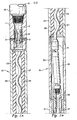
- Figuresla, lb, and lc are a sectional view, from top to bottom, of a drilling motor according to the invention.
- Figure 2 is a side view, partially in section, of a connecting rod assembly according to the invention.
- a bypass valve 11 is shown connected to the lower end of a drill string 13.
- the drill string 13 consists of drill collars and sections of drill pipe, and extends upward through the well bore to a drilling rig at the surface.
- Drilling fluid, or mud is pumped downward through the bore 15 of the drill string 13 into the bore 17 of the bypass valve 11, forcing a shuttle 18 downward to close off bypass ports 21 and to direct the drilling fluid downward into a downhole drilling motor 19.
- the bypass ports 21 allow drilling fluid to exit from the bore 15 of the drilling string 13 when tripping out of the hole, and to fill the bore 15 of the drilling string 13 when tripping into the hole.
- the housing of the downhole drilling motor 19 has three parts.
- the upper housing 23 is connected to the lower end of the bypass valve 11, and houses the progressive cavity motor.
- the progressive cavity motor has a flexible stator 25, which is connected to the upper housing 23, and a helical rotor 27.
- the drilling fluid flows downward through the cavities 29 between the stator 25 and the rotor 27 and causes the rotor 27 to rotate.
- a connecting rod assembly 33 connects the lower end 31 of the rotor 27 to a rotating shaft cap 35 which is firmly connected to a rotating shaft 37.
- a connecting rod housing 39 is connected to the lower end of the upper housing 23 and covers the connect ing rod assembly 33.
- a bearing housing 41 is connected to the lower end of the connecting rod housing 39 and completes the housing of the drilling motor 19.
- the shaft 37 is concentrically located within the bearing housing 41.
- the lower end of the drilling motor 19 is shown in Fig. lc.
- Various radial bearings 43 and thrust bearings 45 transmit loads between the rotating shaft 37 and the relatively non-rotating bearing housing 41.
- the rotating shaft 37 is connected to a rock bit 47, which cuts the bore hole as it rotates. In order to drive the rock bit 47 properly, the shaft 37 must rotate with a true rotation about the longitudinal axis 49 of the shaft 37 and the housing 41.
- the connecting rod assembly 33 is shown in greater detail, and partially in section, in Fig. 2.
- the connecting rod assembly 33 must translate the rotation and gyration of the rotor 27 to the true rotation of the shaft 37.
- a flexible rod 51 extends from the lower end 31 of the rotor 27 to the upper end 35 of the shaft 37.
- the flexible rod 51 must withstand the motor thrust and torque loads, and yet be flexible enough to allow for the eccentricity between the rotor 27 and the shaft 37.
- Each end of the flexible rod 51 has an upset section 53 to reduce stress at the ends, where bending loads are the highest.
- An upper connection 55 and a lower connection 57 are connected to the upset sections 53 of the flexible rod 51.
- connections 55, 57 may be secured to the rod 51 in any of several methods, including interference fit, threads, or pins 59, such as are shown in Fig. 2.
- the connections 55, 57 have threads 61 for connection to the rotor 27 and to the shaft 37.
- the connections 55, 57 also have a plurality of machined flats 63 to facilitate assembly of the drilling motor 19.
- a covering 65 of rubber or other flexible material is placed around the rod 51 to fill the space between the rod 51 and the connections 55, 57.
- the covering 65 protects the flexible rod 51 and supports the rod 51 at each end where bending stresses are the highest.
- the surface of the flexible rod 51 also may be worked, such as by shot peening, or protective coatings may be applied, to increase the life of the flexible rod 51 by reducing surface stresses and by protecting against corrosion and damage due to handling.
- drilling fluid circulates through the drilling motor 19 to rotate the rotor 27.
- the lower end 31 of the rotor 27 also gyrates or orbits.
- the connecting rod assembly 33 must translate the rotation and gyration of the rotor 27 to the true rotation of the shaft 37.
- the flexible rod 51 bends and flexes to compensate for the eccentricity between the rotor 27 and the shaft 37.
- the downhole drilling motor 19 of the invention has several advantages over the prior art. Since the connecting rod assembly 33 operates as a unit, there is no wear between the various parts. Since the connecting rod 51 and the connections 55, 57 are not integral, they may be made from different materials. This fact allows for the selection of an optimum material for the flexible rod 51 and for the connections 55, 57. The connecting rod assembly 33 is shorter than the prior art flexible shafts, thus shortening the overall length of the downhole motor 19.
Landscapes
- Engineering & Computer Science (AREA)
- Mechanical Engineering (AREA)
- General Engineering & Computer Science (AREA)
- Life Sciences & Earth Sciences (AREA)
- Geology (AREA)
- Mining & Mineral Resources (AREA)
- Physics & Mathematics (AREA)
- Environmental & Geological Engineering (AREA)
- Fluid Mechanics (AREA)
- General Life Sciences & Earth Sciences (AREA)
- Geochemistry & Mineralogy (AREA)
- Earth Drilling (AREA)
Applications Claiming Priority (2)
| Application Number | Priority Date | Filing Date | Title |
|---|---|---|---|
| US711322 | 1985-03-13 | ||
| US06/711,322 US4636151A (en) | 1985-03-13 | 1985-03-13 | Downhole progressive cavity type drilling motor with flexible connecting rod |
Publications (1)
| Publication Number | Publication Date |
|---|---|
| EP0196991A1 true EP0196991A1 (fr) | 1986-10-08 |
Family
ID=24857618
Family Applications (1)
| Application Number | Title | Priority Date | Filing Date |
|---|---|---|---|
| EP86630014A Withdrawn EP0196991A1 (fr) | 1985-03-13 | 1986-02-03 | Moteur de forage à grande profondeur |
Country Status (2)
| Country | Link |
|---|---|
| US (1) | US4636151A (fr) |
| EP (1) | EP0196991A1 (fr) |
Cited By (4)
| Publication number | Priority date | Publication date | Assignee | Title |
|---|---|---|---|---|
| WO1991019072A1 (fr) * | 1990-06-07 | 1991-12-12 | Conoco Inc. | Arbre de torsion composite pour moteur a fluide de fond de trou |
| EP0566144A1 (fr) * | 1992-04-16 | 1993-10-20 | Halliburton Company | Moteur de fond de puits avec une connexion flexible |
| US5363929A (en) * | 1990-06-07 | 1994-11-15 | Conoco Inc. | Downhole fluid motor composite torque shaft |
| EP2532833A1 (fr) * | 2011-06-10 | 2012-12-12 | ViscoTec Pumpen-u. Dosiertechnik GmbH | Elément de transport pour une pompe à vis sans fin excentrique et pompe à vis sans fin excentrique |
Families Citing this family (28)
| Publication number | Priority date | Publication date | Assignee | Title |
|---|---|---|---|---|
| US5417281A (en) * | 1994-02-14 | 1995-05-23 | Steven M. Wood | Reverse Moineau motor and pump assembly for producing fluids from a well |
| US5611397A (en) * | 1994-02-14 | 1997-03-18 | Wood; Steven M. | Reverse Moineau motor and centrifugal pump assembly for producing fluids from a well |
| US6183226B1 (en) | 1986-04-24 | 2001-02-06 | Steven M. Wood | Progressive cavity motors using composite materials |
| US5139400A (en) * | 1989-10-11 | 1992-08-18 | Ide Russell D | Progressive cavity drive train |
| US5096004A (en) * | 1989-12-22 | 1992-03-17 | Ide Russell D | High pressure downhole progressive cavity drilling apparatus with lubricating flow restrictor |
| US5007490A (en) * | 1990-06-20 | 1991-04-16 | Ide Russell D | Progressive cavity drive train with elastomeric joint assembly for use in downhole drilling |
| US5090497A (en) * | 1990-07-30 | 1992-02-25 | Baker Hughes Incorporated | Flexible coupling for progressive cavity downhole drilling motor |
| US5135060A (en) * | 1991-03-06 | 1992-08-04 | Ide Russell D | Articulated coupling for use with a downhole drilling apparatus |
| CA2049502C (fr) * | 1991-08-19 | 1994-03-29 | James L. Weber | Dispositif de positionnement de rotor pour pompe utilisee dans une colonne de production |
| CH689792A5 (de) * | 1992-10-08 | 1999-11-15 | Albrecht Bischof | Metallisches Bauelement zum Verbinden von Werkstuecken. |
| US5759019A (en) * | 1994-02-14 | 1998-06-02 | Steven M. Wood | Progressive cavity pumps using composite materials |
| US5527220A (en) * | 1994-03-23 | 1996-06-18 | Halliburton Company | Articulatable joint with multi-faceted ball and socket |
| US5588818A (en) * | 1995-04-20 | 1996-12-31 | Horizon Directional Systems, Inc. | Rotor-to-rotor coupling |
| US6461128B2 (en) | 1996-04-24 | 2002-10-08 | Steven M. Wood | Progressive cavity helical device |
| US6905319B2 (en) | 2002-01-29 | 2005-06-14 | Halliburton Energy Services, Inc. | Stator for down hole drilling motor |
| EP1406016A1 (fr) | 2002-10-04 | 2004-04-07 | Steven M. Wood | Pompes à cavité progressive comportant des matériaux composites |
| US20050089429A1 (en) * | 2003-10-27 | 2005-04-28 | Dyna-Drill Technologies, Inc. | Composite material progressing cavity stators |
| US7083401B2 (en) * | 2003-10-27 | 2006-08-01 | Dyna-Drill Technologies, Inc. | Asymmetric contouring of elastomer liner on lobes in a Moineau style power section stator |
| US7517202B2 (en) * | 2005-01-12 | 2009-04-14 | Smith International, Inc. | Multiple elastomer layer progressing cavity stators |
| US9393648B2 (en) | 2010-03-30 | 2016-07-19 | Smith International Inc. | Undercut stator for a positive displacment motor |
| WO2014014442A1 (fr) | 2012-07-16 | 2014-01-23 | Halliburton Energy Services, Inc. | Moteurs de fond de trou possédant des blocs d'alimentation ajustables |
| CA2831980C (fr) | 2012-11-01 | 2016-06-21 | National Oilwell Varco, L.P. | Rotors legers et flexibles pour dispositifs a deplacement positif |
| WO2014098899A1 (fr) * | 2012-12-21 | 2014-06-26 | Halliburton Energy Services, Inc. | Mécanisme anti-marche arrière pour moteur à boue |
| DE112014001389T5 (de) | 2013-03-15 | 2016-02-18 | Schlumberger Technology B.V. | Bohrmotor-Koppelstange |
| US9689243B2 (en) * | 2013-04-17 | 2017-06-27 | Harrier Technologies, Inc. | Progressive cavity pump with free pump rotor |
| US20150122549A1 (en) * | 2013-11-05 | 2015-05-07 | Baker Hughes Incorporated | Hydraulic tools, drilling systems including hydraulic tools, and methods of using hydraulic tools |
| US11149497B2 (en) | 2016-10-24 | 2021-10-19 | Rival Downhole Tools Lc | Drilling motor with bypass and method |
| CN106762623A (zh) * | 2017-03-07 | 2017-05-31 | 洛阳耿力工程机械有限公司 | 新型螺杆泵传动轴结构 |
Citations (3)
| Publication number | Priority date | Publication date | Assignee | Title |
|---|---|---|---|---|
| US2463341A (en) * | 1946-02-25 | 1949-03-01 | Fmc Corp | Motor pump with sand trap and piming means |
| GB628203A (en) * | 1947-09-04 | 1949-08-24 | Fmc Corp | Improvements in meshing-screw pumps |
| US4397619A (en) * | 1979-03-14 | 1983-08-09 | Orszagos Koolaj Es Gazipari Troszt | Hydraulic drilling motor with rotary internally and externally threaded members |
Family Cites Families (13)
| Publication number | Priority date | Publication date | Assignee | Title |
|---|---|---|---|---|
| US2028407A (en) * | 1932-04-29 | 1936-01-21 | Moineau Rene Joseph Louis | Gear mechanism |
| US2346426A (en) * | 1941-10-30 | 1944-04-11 | Fmc Corp | Flexible rotary drive coupling |
| US2621605A (en) * | 1945-10-12 | 1952-12-16 | Clayton Mark & Company | Pump |
| US3155187A (en) * | 1957-08-05 | 1964-11-03 | Gen Motors Corp | Power shaft |
| US3340814A (en) * | 1966-11-04 | 1967-09-12 | Oskar Seidl | Protection devices for the drive connection of an eccentric worm pump |
| GB1220848A (en) * | 1968-06-05 | 1971-01-27 | Mono Pumps Ltd | Rotary pump or motor with an eccentrically rotating rotor |
| US3600113A (en) * | 1969-10-20 | 1971-08-17 | Mono Pumps Ltd | Rotary pump or motor with an axially rotating rotor |
| US3894818A (en) * | 1973-04-27 | 1975-07-15 | Smith International | In-hole motors |
| US4080115A (en) * | 1976-09-27 | 1978-03-21 | A-Z International Tool Company | Progressive cavity drive train |
| US4140444A (en) * | 1977-08-26 | 1979-02-20 | Allen Clifford H | Flexible shaft assembly for progressing cavity pump |
| US4187918A (en) * | 1978-06-12 | 1980-02-12 | Wallace Clark | Down-hole earth drilling motor capable of free circulation |
| FR2442367A1 (fr) * | 1978-11-23 | 1980-06-20 | Mecanique Metallurgie Ste Gle | Perfectionnements aux dispositifs de montage des bielles d'entrainement pour rotors de pompes a vis |
| GB2084697B (en) * | 1980-09-24 | 1984-04-26 | Inst Burovoi Tekhnik | Planetary mechanism |
-
1985
- 1985-03-13 US US06/711,322 patent/US4636151A/en not_active Expired - Lifetime
-
1986
- 1986-02-03 EP EP86630014A patent/EP0196991A1/fr not_active Withdrawn
Patent Citations (3)
| Publication number | Priority date | Publication date | Assignee | Title |
|---|---|---|---|---|
| US2463341A (en) * | 1946-02-25 | 1949-03-01 | Fmc Corp | Motor pump with sand trap and piming means |
| GB628203A (en) * | 1947-09-04 | 1949-08-24 | Fmc Corp | Improvements in meshing-screw pumps |
| US4397619A (en) * | 1979-03-14 | 1983-08-09 | Orszagos Koolaj Es Gazipari Troszt | Hydraulic drilling motor with rotary internally and externally threaded members |
Cited By (4)
| Publication number | Priority date | Publication date | Assignee | Title |
|---|---|---|---|---|
| WO1991019072A1 (fr) * | 1990-06-07 | 1991-12-12 | Conoco Inc. | Arbre de torsion composite pour moteur a fluide de fond de trou |
| US5363929A (en) * | 1990-06-07 | 1994-11-15 | Conoco Inc. | Downhole fluid motor composite torque shaft |
| EP0566144A1 (fr) * | 1992-04-16 | 1993-10-20 | Halliburton Company | Moteur de fond de puits avec une connexion flexible |
| EP2532833A1 (fr) * | 2011-06-10 | 2012-12-12 | ViscoTec Pumpen-u. Dosiertechnik GmbH | Elément de transport pour une pompe à vis sans fin excentrique et pompe à vis sans fin excentrique |
Also Published As
| Publication number | Publication date |
|---|---|
| US4636151A (en) | 1987-01-13 |
Similar Documents
| Publication | Publication Date | Title |
|---|---|---|
| US4636151A (en) | Downhole progressive cavity type drilling motor with flexible connecting rod | |
| US4679638A (en) | Downhole progressive cavity type drilling motor with flexible connecting rod | |
| US5090497A (en) | Flexible coupling for progressive cavity downhole drilling motor | |
| US4676725A (en) | Moineau type gear mechanism with resilient sleeve | |
| US8701797B2 (en) | Bearing assembly for downhole motor | |
| US4646856A (en) | Downhole motor assembly | |
| US8181720B2 (en) | Sealing system and bi-directional thrust bearing arrangement for a downhole motor | |
| CA2271525C (fr) | Methode de foration descendante et appareil connexe | |
| EP0170681B1 (fr) | Assemblage de moteur et paliers de fond de puits | |
| US4246976A (en) | Down hole drilling motor with pressure balanced bearing seals | |
| US4665997A (en) | Pressure balanced bearing assembly for downhole motors | |
| CA2604002A1 (fr) | Forage avec tubage | |
| CA2780515C (fr) | Ensemble moteur de fond de trou | |
| US10253578B2 (en) | Drill motor connecting rod | |
| US6629571B1 (en) | Downhole motor assembly | |
| JPS62258179A (ja) | 循環ポンプとその操作方法 | |
| US9546518B2 (en) | Power section and transmission of a downhole drilling motor | |
| CA3038945A1 (fr) | Mecanisme de tige d'entrainement amortisseur-alternatif | |
| CN107532452B (zh) | 用于钻井马达的cv接头和方法 | |
| US5964307A (en) | Shock tool for use in directional drilling | |
| CA2866253A1 (fr) | Arbre d'entrainement de moteur a boue avec paliers ameliores | |
| GB2152588A (en) | Downhole rotary fluid- pressure motor | |
| CA1257865A (fr) | Joint d'etancheite pour cuvettes de lubrifiant sur outil de forage | |
| EP3749827B1 (fr) | Coupleur de composant de forage pour renforcement | |
| Tschirky | New developments in down-hole motors for improved drilling performance |
Legal Events
| Date | Code | Title | Description |
|---|---|---|---|
| PUAI | Public reference made under article 153(3) epc to a published international application that has entered the european phase |
Free format text: ORIGINAL CODE: 0009012 |
|
| AK | Designated contracting states |
Kind code of ref document: A1 Designated state(s): DE FR GB |
|
| 17P | Request for examination filed |
Effective date: 19870226 |
|
| STAA | Information on the status of an ep patent application or granted ep patent |
Free format text: STATUS: THE APPLICATION IS DEEMED TO BE WITHDRAWN |
|
| 18D | Application deemed to be withdrawn |
Effective date: 19880829 |
|
| RIN1 | Information on inventor provided before grant (corrected) |
Inventor name: EPPINK, JAY MILTON |