EP0196961B1 - Sun visor for a motor vehicle - Google Patents
Sun visor for a motor vehicle Download PDFInfo
- Publication number
- EP0196961B1 EP0196961B1 EP86400569A EP86400569A EP0196961B1 EP 0196961 B1 EP0196961 B1 EP 0196961B1 EP 86400569 A EP86400569 A EP 86400569A EP 86400569 A EP86400569 A EP 86400569A EP 0196961 B1 EP0196961 B1 EP 0196961B1
- Authority
- EP
- European Patent Office
- Prior art keywords
- mirror
- support
- sun visor
- shield
- strips
- Prior art date
- Legal status (The legal status is an assumption and is not a legal conclusion. Google has not performed a legal analysis and makes no representation as to the accuracy of the status listed.)
- Expired
Links
- 239000000463 material Substances 0.000 claims description 5
- 229920003023 plastic Polymers 0.000 claims description 5
- 239000004033 plastic Substances 0.000 claims description 5
- 230000002093 peripheral effect Effects 0.000 claims description 4
- 229920002292 Nylon 6 Polymers 0.000 claims description 2
- 239000011521 glass Substances 0.000 claims description 2
- 230000002787 reinforcement Effects 0.000 claims 3
- 239000004800 polyvinyl chloride Substances 0.000 description 9
- 229920000915 polyvinyl chloride Polymers 0.000 description 8
- 239000011248 coating agent Substances 0.000 description 7
- 238000000576 coating method Methods 0.000 description 7
- 239000006260 foam Substances 0.000 description 4
- 210000002105 tongue Anatomy 0.000 description 4
- 238000004519 manufacturing process Methods 0.000 description 3
- 239000002184 metal Substances 0.000 description 3
- 239000004743 Polypropylene Substances 0.000 description 1
- 239000000470 constituent Substances 0.000 description 1
- 230000007423 decrease Effects 0.000 description 1
- 230000007547 defect Effects 0.000 description 1
- 238000002347 injection Methods 0.000 description 1
- 239000007924 injection Substances 0.000 description 1
- 238000003780 insertion Methods 0.000 description 1
- 230000037431 insertion Effects 0.000 description 1
- 238000009434 installation Methods 0.000 description 1
- 238000000034 method Methods 0.000 description 1
- -1 polypropylene Polymers 0.000 description 1
- 229920001155 polypropylene Polymers 0.000 description 1
- 238000003466 welding Methods 0.000 description 1
Images


Classifications
-
- B—PERFORMING OPERATIONS; TRANSPORTING
- B60—VEHICLES IN GENERAL
- B60J—WINDOWS, WINDSCREENS, NON-FIXED ROOFS, DOORS, OR SIMILAR DEVICES FOR VEHICLES; REMOVABLE EXTERNAL PROTECTIVE COVERINGS SPECIALLY ADAPTED FOR VEHICLES
- B60J3/00—Antiglare equipment associated with windows or windscreens; Sun visors for vehicles
- B60J3/02—Antiglare equipment associated with windows or windscreens; Sun visors for vehicles adjustable in position
- B60J3/0204—Sun visors
- B60J3/0278—Sun visors structure of the body
- B60J3/0282—Sun visors structure of the body specially adapted for a courtesy mirror
Definitions
- the present invention relates to a sun visor for motor vehicles, of the type mentioned in the preamble of claim 1. (See document DE-A-2220711)
- the mirror is fixed to the PVC covering by means of a metal or plastic frame which is itself held in place by a rigid PVC plate, welded to the covering PVC. After installation on the mirror, the legs of the frame are folded down.
- This device is expensive because it requires a large workforce, intermediate stocks as well as handling.
- documents DE-A-2 619 844 and DE-A-2 220 711 describe sun visors, the mirror of which is arranged in a removable support which can be fixed in a housing by clipping on retaining means integral with the screen of the sun visor.
- the mirrors with their support frames must be placed in the sun visor before placing the final covering sheet, which is then welded to the support frame or to the mirror itself.
- the sun visor is characterized by the means mentioned in the characterizing part of claim 1.
- the assembly of the mirror previously slipped into its support frame is done after the final coating has been put in place, is very simple and rapid, which significantly reduces the labor required.
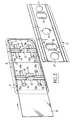
- the sun visor shown in Figures 1 to 3 is intended for motor vehicles, and it comprises a screen 1, preferably made of injected foam, covered with a coating 2 of a suitable plastic material such as a sheet of polyvinyl chloride (PVC) and provided with a mirror 3 fixed in a housing 4 provided in the screen 1.
- a screen 1 preferably made of injected foam
- a coating 2 of a suitable plastic material such as a sheet of polyvinyl chloride (PVC) and provided with a mirror 3 fixed in a housing 4 provided in the screen 1.
- PVC polyvinyl chloride
- An axis 5 the two ends of which are embedded in the screen 1, allows the sun visor to be articulated to the roof of the vehicle.
- the mirror 3 is arranged in a removable support 6 which can be fixed in the housing 4 by clipping onto retaining means 7 secured to the screen 1.
- the support 7 is constituted by a frame whose periphery matches the outline of the mirror 3, which is rectangular in this embodiment, and can be slid into the frame 6.
- This therefore includes a peripheral rim 8 conforming to the outline of the mirror 3, as well as a rib 9 perpendicular to the rim 8 and which extends over the entire periphery thereof with the exception of a small side, to which therefore corresponds an opening (FIG. 2) making it possible to introduce the mirror 3 into the frame 6.
- the long sides of the rim 8 are connected by two transverse bars 11 each provided with a pair of lugs 12 oriented perpendicular to the general plane of the bars 11 and the rim 8, as well as a pair of longitudinal tongues 13, parallel to each other and extending substantially in the same plane as the rim 8 and the bars 11.
- Chamfers 13a are provided on the ends of the tongues 13 facing the insertion opening of the mirror 3, which can thus slide over the chamfered ends 13a during its introduction into the frame 6, between the internal periphery of the rim 8 on which it is held in abutment by the tongues 13.
- the latter also for this purpose comprise ends 13b formed on the other side of the chamfers 13a with respect to the bars 11.
- the two pairs of legs 12 are provided at their ends with chamfered projections 14 making it possible to clip the legs 12, by elastic spacing of the latter, on the opposite edges 15 of two openings 16 each formed opposite a pair of legs 12 in a rigid constituent insert the aforementioned means 7 for retaining the support 6 and the mirror 3.
- the insert 7, preferably metallic, is pierced, in this embodiment, with three circular holes 17 intended to be crossed by bosses 18, 19 (FIG. 1) of injected foam serving as supports for the mirror 3.
- the metal insert 7 is placed at the bottom of the housing 4 and covered with a film of foam then, with the assembly of the screen 1, is covered by the coating. 2 of PVC.
- the mirror 3 is on its side slid into the frame 6, between the tongues 13 and the flange 8 on which it is pressed. After which it only remains to snap the legs 12 by their projections 14 on the opposite edges 15 of the openings 16, the inclined faces of the projections 14 sliding on these edges, while the legs 12 approach one of the other, then move away elastically by gripping the insert 7 through the sheet 2.
- the mirror 3 is then in place.
- the support frame 6 is made of a plastic material having good temperature resistance, for example made of glass-filled polyamide 6/6, which withstands temperatures which may exceed 105 ° C.
- the means for retaining the armature 6 are constituted by two plates 21 made in one piece with a half-shell 22 constituting one half of the screen of the sun visor in accordance with French patent 81 18 233 of the Applicant, this half-shell being produced for example from polypropylene.
- the two bars 21 are arranged transversely in a housing 23 of the half-shell 22, and are each pierced with an opening 24 on the opposite edges 24a, which can snap the two pairs of elastic tabs 12 (Fig. 5) .
- the mounting method is the same as in the first embodiment, and the internal periphery of the peripheral rim 8 comes to bear on the corresponding periphery of the housing 23.
Description
La présente invention a pour objet un pare- soleil pour véhicules automobiles, du type mentionné au préambule de la revendication 1. (Voir document DE-A-2220711 )The present invention relates to a sun visor for motor vehicles, of the type mentioned in the preamble of claim 1. (See document DE-A-2220711)
Dans certains pare-soleil actuels, le miroir est fixé sur le revêtement en PVC par l'intermédiaire d'un encadrement métallique ou plastique qui est lui-même maintenu en place par une plaquette de PVC rigide, soudée sur le PVC de recouvrement. Après la mise en place sur le miroir, les pattes de l'encadrement sont rabattues.In some current sun visors, the mirror is fixed to the PVC covering by means of a metal or plastic frame which is itself held in place by a rigid PVC plate, welded to the covering PVC. After installation on the mirror, the legs of the frame are folded down.
Ce dispositif est onéreux du fait qu'il nécessite une main d'oeuvre importante, des stocks intermédiaires ainsi que des manutentions.This device is expensive because it requires a large workforce, intermediate stocks as well as handling.
Par ailleurs, les documents DE-A-2 619 844 et DE-A-2 220 711 décrivent des pare-soleil dont le miroir est disposé dans un support amovible pouvant être fixé dans un logement par clipsage sur des moyens de retenue solidaires de l'écran du pare-soleil.Furthermore, documents DE-A-2 619 844 and DE-A-2 220 711 describe sun visors, the mirror of which is arranged in a removable support which can be fixed in a housing by clipping on retaining means integral with the screen of the sun visor.
Dans ces réalisations connues, les miroirs avec leurs cadres supports doivent être disposés dans le pare-soleil avant mise en place de la feuille de revêtement finale, qui est ensuite soudée au cadre-support ou au miroir lui-même.In these known embodiments, the mirrors with their support frames must be placed in the sun visor before placing the final covering sheet, which is then welded to the support frame or to the mirror itself.
Tous ces dispositifs présentent les inconvénients suivants:
- - la tenue en température du cadre support est insuffisante, car celui-ci ne peut être qu'en PVC pour être soudable sur le revêtement. Sa déformation à la chaleur commence donc à partir de 75°C, alors que les constructeurs exigent couramment 105°C sans déformation, au regard des nouvelles normes de qualité de plus en plus sévères;
- - impossibilité de démonter le miroir sans détruire le revêtement;
- - esthétique peu satisfaisante;
- - coût de fabrication accru par la soudure du revêtement sur le cadre support du miroir;
- - bruyance du miroir dans son logement;
- - défaut sur le revêtement de PVC dû au marquage des coins de l'encadrement.
- - the temperature resistance of the support frame is insufficient, because it can only be PVC to be weldable on the coating. Its heat deformation therefore begins from 75 ° C, whereas manufacturers commonly require 105 ° C without deformation, in the light of the increasingly stringent new quality standards;
- - inability to dismantle the mirror without destroying the coating;
- - unsatisfactory aesthetics;
- - increased manufacturing cost by welding the coating to the mirror support frame;
- - noisiness of the mirror in its housing;
- - defect on the PVC coating due to the marking of the corners of the frame.
L'invention a pour but d'éliminer ces inconvénients. Suivant l'invention, le pare-soleil est caractérisé par les moyens mentionnés à la partie caractéri- sante de la revendication 1.The invention aims to eliminate these drawbacks. According to the invention, the sun visor is characterized by the means mentioned in the characterizing part of claim 1.
Le montage du miroir préalablement glissé dans son armature de support se fait après mise en place du revêtement final, est très simple et rapide, ce qui réduit notablement la main d'oeuvre nécessaire.The assembly of the mirror previously slipped into its support frame is done after the final coating has been put in place, is very simple and rapid, which significantly reduces the labor required.
D'autres particularités et avantages de l'invention apparaîtront au cours de la description qui va suivre, faite en référence aux dessins annexés qui en illustrent deux modes de réalisation à titre d'exemples non limitatifs:
- - la Figure 1 est une vue en perspective éclatée et avec arrachement partiel d'une première forme de réalisation du pare-soleil conforme à l'invention et de son miroir partiellement engagé dans son support;
- - la Figure 2 est une vue en perspective, à échelle agrandie par rapport à la Figure 1, de l'armature de support du miroir et d'un insert métallique prévu pour être disposé dans le logement du paresoleil et pour retenir l'armature de support du miroir par clipsage;
- - la Figure 3 est une vue en coupe longitudinale avec arrachements du pare-soleil des Figures 1 et 2 et de l'armature de support du miroir;
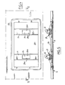
- - la Figure 4 est une vue de dessus en plan des moyens de retenue du miroir et de son support, formées dans un pare-soleil selon un second mode de réalisation de l'invention;
- - la Figure 5 est une vue en coupe longitudinale du miroir logé dans un support correspondant suivant V-V de la Figure 4.
- - Figure 1 is an exploded perspective view with partial cutaway of a first embodiment of the sun visor according to the invention and its mirror partially engaged in its support;
- - Figure 2 is a perspective view, on an enlarged scale compared to Figure 1, of the mirror support frame and a metal insert intended to be disposed in the housing of the sunshade and to retain the frame mirror support by clipping;
- - Figure 3 is a longitudinal sectional view with cutaway of the sun visor of Figures 1 and 2 and the mirror support frame;
- - Figure 4 is a top plan view of the mirror retaining means and its support, formed in a sun visor according to a second embodiment of the invention;
- FIG. 5 is a view in longitudinal section of the mirror housed in a corresponding support according to VV of FIG. 4.
Le pare-soleil représenté aux Figures 1 à 3 est destiné aux véhicules automobiles, et il comporte un écran 1, réalisé de préférence en mousse injectée, recouvert d'un revêtement 2 en une matière plastique appropriée telle qu'une feuille de chlorure de polyvinyle (PVC) et muni d'un miroir 3 fixé dans un logement 4 ménagé dans l'écran 1.The sun visor shown in Figures 1 to 3 is intended for motor vehicles, and it comprises a screen 1, preferably made of injected foam, covered with a
Un axe 5 dont les deux extrémités sont noyées dans l'écran 1 permet d'articuler le pare-soleil au pavillon du véhicule.An
Le miroir 3 est disposé dans un support amovible 6 pouvant être fixé dans le logement 4 par clipsage sur des moyens de retenue 7 solidaires de l'écran 1. Dans ce mode de réalisation, le support 7 est constitué par une armature dont la périphérie épouse le contour du miroir 3, lequel est rectangulaire dans cette réalisation, et peut- être glissé dans l'armature 6. Celle-ci comprend donc un rebord périphérique 8 épousant le contour du miroir 3, ainsi qu'une nervure 9 perpendiculaire au rebord 8 et qui s'étend sur tout le pourtour de celui-ci à l'exception d'un petit côté, auquel correspond donc une ouverture (Fig.2) permettant d'introduire le miroir 3 dans l'armature 6. Les grands côtés du rebord 8 sont reliés par deux barrettes transversales 11 munies chacune d'une paire de pattes 12 orientées perpendiculairement au plan général des barrettes 11 et du rebord 8, ainsi que d'une paire de languettes longitudinales 13, parallèles entre elles et s'étendant sensiblement dans le même plan que le rebord 8 et les barrettes 11.The
Des chanfreins 13a sont ménagés sur les extrémités des languettes 13 tournées vers l'ouverture d'insertion du miroir 3, qui peut ainsi glisser sur les extrémités chanfreinées 13a durant son introduction dans l'armature 6, entre le pourtour interne du rebord 8 sur lequel il est maintenu en appui par les languettes 13. Ces dernières comportent également à cet effet des extrémités 13b ménagées de l'autre côté des chanfreins 13a par rapport aux barrettes 11.Chamfers 13a are provided on the ends of the
Les deux paires de pattes 12 sont munies à leurs extrémités de ressauts chanfreinés 14 permettant de clipser les pattes 12, par écartement élastique de celles-ci, sur les bords opposés 15 de deux ouvertures 16 formées chacune en regard d'une paire de pattes 12 dans un insert rigide constituant les moyens précités 7 de retenue du support 6 et du miroir 3.The two pairs of
L'insert 7, de préférence métallique, est percé, dans cet exemple de réalisation, de trois trous circulaires 17 destinés à être traversés par des bossages 18, 19 (Figure 1) de mousse injectée servant d'appuis au miroir 3.The
Durant la fabrication de l'écran 1 par injection de mousse, l'insert métallique 7 est placé au fond du logement 4 et recouvert d'une pellicule de mousse puis, avec l'ensemble de l'écran 1, est recouvert par le revêtement 2 de PVC. Le miroir 3 est de son côté glissé dans l'armature 6, entre les languettes 13 et le rebord 8 sur lequel il est plaqué. Après quoi il ne reste plus qu'à encliqueter les pattes 12 par leurs ressauts 14 sur les bords opposés 15 des ouvertures 16, les faces inclinées des ressauts 14 glissant sur ces bords, tandis que les pattes 12 se rapprochent l'une de l'autre, puis s'écartent élastiquement en agrippant l'insert 7 au travers de la feuille 2.During the manufacture of the screen 1 by injection of foam, the
Le miroir 3 est alors en place.The
L'armature de support 6 est réalisée en une matière plastique ayant une bonne tenue à la température, par exemple en polyamide 6/6 chargé de verre, qui résiste à des températures pouvant dépasser 105°C.The
La simplicité du montage du miroir 3 et de son support 6 économise une main-d'oeuvre importante, donc diminue le coût de réalisation du pare- soleil. De plus, la mise en oeuvre d'un support 6 réalisé d'une seule pièce en un matériau plastique approprié, tel que celui mentionné ci-dessus, améliore la tenue en température du système de fixation du pare-soleil. La solidité de cette fixation est également améliorée par rapport à la technique antérieure, de même que l'esthétique du miroir 3, dont seul l'encadrement constitué par la face extérieure du rebord périphérique 8 est visible, une fois l'ensemble 3, 6 mis en place.The simplicity of mounting the
Dans la seconde forme de réalisation du pare- soleil, illustrée aux Fig.4 et 5, les moyens de retenue de l'armature 6 sont constitués par deux plaquettes 21 venues de matière avec une demi-coquille 22 constituant une moitié de l'écran du pare-soleil conformément au brevet français 81 18 233 de la Demanderesse, cette demi-coquille étant réalisée par exemple en polypropylène.In the second embodiment of the sun visor, illustrated in FIGS. 4 and 5, the means for retaining the
Les deux barrettes 21 sont disposées transversalement dans un logement 23 de la demi-coquille 22, et sont percées chacune d'une ouverture 24 sur les bords opposés 24a, lesquels peuvent s'encliqueter les deux paires de pattes élastiques 12 (Fig. 5).The two
Le mode de montage est le même que dans la première forme de réalisation, et le pourtour interne du rebord périphérique 8 vient s'appuyer sur le pourtour correspondant du logement 23.The mounting method is the same as in the first embodiment, and the internal periphery of the
En variante, il serait possible de ne prévoir qu'une seule paire de pattes 12 de clipsage sur l'armature 6 ainsi qu'une seule ouverture correspondante 16 ou 24, à condition bien entendu que ces pattes et les bords de l'ouverture associée soient suffisamment écartés pour assurer une fixation convenable du miroir 3. Dans la réalisation des Fig.4 et 5, les deux plaquettes transversales 21 seraient donc remplacées par une seule plaquette percée d'un trou de largeur suffisante.Alternatively, it would be possible to provide only a single pair of
Claims (2)
Applications Claiming Priority (2)
| Application Number | Priority Date | Filing Date | Title |
|---|---|---|---|
| FR8504427 | 1985-03-25 | ||
| FR8504427A FR2579150B1 (en) | 1985-03-25 | 1985-03-25 | SUN VISOR FOR MOTOR VEHICLE |
Publications (2)
| Publication Number | Publication Date |
|---|---|
| EP0196961A1 EP0196961A1 (en) | 1986-10-08 |
| EP0196961B1 true EP0196961B1 (en) | 1988-10-26 |
Family
ID=9317551
Family Applications (1)
| Application Number | Title | Priority Date | Filing Date |
|---|---|---|---|
| EP86400569A Expired EP0196961B1 (en) | 1985-03-25 | 1986-03-18 | Sun visor for a motor vehicle |
Country Status (9)
| Country | Link |
|---|---|
| US (1) | US4685723A (en) |
| EP (1) | EP0196961B1 (en) |
| JP (1) | JPS61257319A (en) |
| BR (1) | BR8601310A (en) |
| CA (1) | CA1270281A (en) |
| DE (1) | DE3660994D1 (en) |
| ES (1) | ES293342Y (en) |
| FR (1) | FR2579150B1 (en) |
| MX (1) | MX167483B (en) |
Families Citing this family (19)
| Publication number | Priority date | Publication date | Assignee | Title |
|---|---|---|---|---|
| US4791537A (en) * | 1984-07-02 | 1988-12-13 | Irvin Industries, Inc. | Vehicle accessory assembly with sliding door for mounting on a visor or other interior panel |
| US4711483A (en) * | 1986-01-21 | 1987-12-08 | Irvin Industries, Inc. | Motor vehicle visor with removable mirror assembly |
| US4858983A (en) * | 1988-04-04 | 1989-08-22 | White Jay E | Sun visor frame and mounting structure |
| ES2006885A6 (en) * | 1988-04-08 | 1989-05-16 | Gabas Cebollero Carlos | Vanity mirror for automobiles. |
| GB2218059B (en) * | 1988-04-30 | 1991-09-11 | Austin Rover Group | A sun visor |
| US4866579A (en) * | 1988-05-23 | 1989-09-12 | Prince Corporation | Snap-in mirror package |
| US4922391A (en) * | 1989-01-12 | 1990-05-01 | Prince Corporation | Vanity mirror package |
| SE465719B (en) * | 1990-01-31 | 1991-10-21 | Autopart Sweden Ab | SUN PROTECTION FOR MOTOR VEHICLE |
| DE4023243C1 (en) * | 1990-07-21 | 1991-11-21 | Gebr. Happich Gmbh, 5600 Wuppertal, De | |
| US5338082A (en) * | 1992-04-15 | 1994-08-16 | Plasta Fiber Industries Corp. | Apparatus for securing fabric to a visor |
| US5301994A (en) * | 1992-10-14 | 1994-04-12 | Plasta Fiber Industries Corp. | Dual synchronous opening mirror doors for sun visors |
| US5441325A (en) * | 1993-07-07 | 1995-08-15 | Prince Corporation | Vanity mirror with opposed sliding covers |
| DE19635684B4 (en) * | 1996-09-03 | 2004-09-30 | Johnson Controls Interiors Gmbh & Co. Kg | Sun visors for vehicles |
| US6254168B1 (en) | 2000-01-31 | 2001-07-03 | Crotty Corporation | Sun visor with vanity mirror |
| US6698815B1 (en) * | 2002-10-02 | 2004-03-02 | Grupo Antolin Ingenieria, S.A. | Sun visor with mirror assembly |
| DE10340079B4 (en) * | 2003-08-30 | 2008-07-03 | Johnson Controls Interiors Gmbh & Co. Kg | lens hood |
| DE502008000304D1 (en) * | 2008-03-25 | 2010-02-25 | Smr Patents Sarl | Sun visor with plastic mirror |
| DE102017004901A1 (en) | 2017-05-20 | 2017-11-16 | Daimler Ag | Sun visor for a vehicle and method of mounting such a sun visor |
| ES1225564Y (en) * | 2018-12-17 | 2019-05-20 | Grupo Antolin Ingenieria S A U | PARASOL |
Family Cites Families (7)
| Publication number | Priority date | Publication date | Assignee | Title |
|---|---|---|---|---|
| US3843236A (en) * | 1972-11-24 | 1974-10-22 | Donnelly Mirrors Inc | Shatter-resistant mirror mounting |
| DE2619844C3 (en) * | 1976-05-05 | 1981-03-26 | Gebr. Happich Gmbh, 42285 Wuppertal | Sun visors, in particular for vehicles |
| US4068930A (en) * | 1976-12-27 | 1978-01-17 | Prince Corporation | Visor assembly and covered vanity mirror |
| JPS596515B2 (en) * | 1977-03-17 | 1984-02-13 | 松下電器産業株式会社 | integrated circuit device |
| US4275916A (en) * | 1979-04-19 | 1981-06-30 | Prince Corporation | Visor with storage compartment |
| FR2513578A1 (en) * | 1981-09-28 | 1983-04-01 | Mecanismes Comp Ind De | SUN VISORS, ESPECIALLY FOR MOTOR VEHICLES |
| US4494789A (en) * | 1983-05-02 | 1985-01-22 | Prince Corporation | Visor covering |
-
1985
- 1985-03-25 FR FR8504427A patent/FR2579150B1/en not_active Expired
-
1986
- 1986-03-18 EP EP86400569A patent/EP0196961B1/en not_active Expired
- 1986-03-18 DE DE8686400569T patent/DE3660994D1/en not_active Expired
- 1986-03-24 CA CA000504939A patent/CA1270281A/en not_active Expired - Fee Related
- 1986-03-24 ES ES1986293342U patent/ES293342Y/en not_active Expired
- 1986-03-24 MX MX001962A patent/MX167483B/en unknown
- 1986-03-24 BR BR8601310A patent/BR8601310A/en not_active IP Right Cessation
- 1986-03-25 JP JP61067003A patent/JPS61257319A/en active Pending
- 1986-03-25 US US06/843,527 patent/US4685723A/en not_active Expired - Lifetime
Also Published As
| Publication number | Publication date |
|---|---|
| ES293342Y (en) | 1987-09-16 |
| MX167483B (en) | 1993-03-25 |
| FR2579150B1 (en) | 1987-06-26 |
| US4685723A (en) | 1987-08-11 |
| BR8601310A (en) | 1986-12-02 |
| CA1270281A (en) | 1990-06-12 |
| DE3660994D1 (en) | 1988-12-01 |
| ES293342U (en) | 1986-08-01 |
| FR2579150A1 (en) | 1986-09-26 |
| JPS61257319A (en) | 1986-11-14 |
| EP0196961A1 (en) | 1986-10-08 |
Similar Documents
| Publication | Publication Date | Title |
|---|---|---|
| EP0196961B1 (en) | Sun visor for a motor vehicle | |
| FR2599792A1 (en) | Element for attaching a flat bundle of conducting wires | |
| EP3583825B1 (en) | Electrical connection interface of an electric heating device for a motor vehicle | |
| EP0706159B1 (en) | Marking device, particularly for electric conductor or junction block | |
| FR2945521A1 (en) | TRANSPORT KEY WITH EASY EXTRACTION FOR HOLLOW PROFILES OR DEFORMABLE HOLLOW PIECES | |
| FR2793741A1 (en) | Mechanism for fitting radiator in car comprises support and fixing ring, which is attached in rotation on support through coaxial apertures | |
| FR2505268A1 (en) | Housing for vehicle heater - has tongue on one half-shell engaging channel in other with seal between | |
| EP1666309B1 (en) | Fastening clip for vehicle liner, combination of clip and liner and vehicle having same | |
| EP0829689A1 (en) | Sealing means for apparatus for closing a ventilation conduit, in particular fire or exhaust damper | |
| EP2585342B1 (en) | Intermediate attachment part for vehicle trimming | |
| EP0780584A1 (en) | Device for fixing in place a heat exchanger for a vehicle heating and/or air conditioning installation | |
| EP1584516A1 (en) | Mounting assembly for a vehicle roof rail on a vehicle roof | |
| EP1164676B1 (en) | Mounting device for an electrical apparatus on a cable duct | |
| EP0547929B1 (en) | Electrical socket, in particular for automotive vehicles | |
| FR2943017A1 (en) | PROFILE FOR VEHICLE CLOSURE CLOSURE ELEMENT AND CORRESPONDING CLOSURE ELEMENT | |
| FR3058502B1 (en) | DEVICE FOR NON-SCREW MOUNTING OF A PROJECTOR CONTROL BOX ON THIS PROJECTOR | |
| FR2652142A1 (en) | Improvements to fish joints for cable paths made as a lattice or the like | |
| EP1470942B1 (en) | Arrangement to fasten a support of a sun curtain | |
| FR2544411A1 (en) | One-piece fixing device with a retained nut | |
| BE1006912A3 (en) | SPACER FOR ENCLOSURES FOR ELECTRICAL APPLIANCES AVAILABLE SIDE BY SIDE. | |
| EP1432091A1 (en) | Coupling element for raceway base | |
| FR2768199A1 (en) | Sliding fixing for plastic part on vehicle bodywork support | |
| FR3102454A1 (en) | TRIM SUPPORT FOR A MOTOR VEHICLE DOOR, ESPECIALLY OF THE TAILGATE TYPE | |
| FR2755069A1 (en) | SUN VISOR WITH ACCESSORY | |
| FR2769943A1 (en) | Corner piece for window frame seal |
Legal Events
| Date | Code | Title | Description |
|---|---|---|---|
| PUAI | Public reference made under article 153(3) epc to a published international application that has entered the european phase |
Free format text: ORIGINAL CODE: 0009012 |
|
| AK | Designated contracting states |
Kind code of ref document: A1 Designated state(s): DE GB IT SE |
|
| 17P | Request for examination filed |
Effective date: 19870116 |
|
| RAP1 | Party data changed (applicant data changed or rights of an application transferred) |
Owner name: ROCKWELL-CIM |
|
| 17Q | First examination report despatched |
Effective date: 19870702 |
|
| ITF | It: translation for a ep patent filed |
Owner name: INVENTION S.N.C. |
|
| GRAA | (expected) grant |
Free format text: ORIGINAL CODE: 0009210 |
|
| AK | Designated contracting states |
Kind code of ref document: B1 Designated state(s): DE GB IT SE |
|
| REF | Corresponds to: |
Ref document number: 3660994 Country of ref document: DE Date of ref document: 19881201 |
|
| GBT | Gb: translation of ep patent filed (gb section 77(6)(a)/1977) | ||
| PLBE | No opposition filed within time limit |
Free format text: ORIGINAL CODE: 0009261 |
|
| STAA | Information on the status of an ep patent application or granted ep patent |
Free format text: STATUS: NO OPPOSITION FILED WITHIN TIME LIMIT |
|
| 26N | No opposition filed | ||
| PGFP | Annual fee paid to national office [announced via postgrant information from national office to epo] |
Ref country code: GB Payment date: 19930312 Year of fee payment: 8 |
|
| PGFP | Annual fee paid to national office [announced via postgrant information from national office to epo] |
Ref country code: SE Payment date: 19930323 Year of fee payment: 8 |
|
| ITTA | It: last paid annual fee | ||
| PG25 | Lapsed in a contracting state [announced via postgrant information from national office to epo] |
Ref country code: GB Effective date: 19940318 |
|
| PG25 | Lapsed in a contracting state [announced via postgrant information from national office to epo] |
Ref country code: SE Free format text: LAPSE BECAUSE OF NON-PAYMENT OF DUE FEES Effective date: 19940319 |
|
| GBPC | Gb: european patent ceased through non-payment of renewal fee |
Effective date: 19940318 |
|
| EUG | Se: european patent has lapsed |
Ref document number: 86400569.9 Effective date: 19941010 |
|
| PGFP | Annual fee paid to national office [announced via postgrant information from national office to epo] |
Ref country code: DE Payment date: 19950220 Year of fee payment: 10 |
|
| PG25 | Lapsed in a contracting state [announced via postgrant information from national office to epo] |
Ref country code: DE Effective date: 19961203 |
|
| PG25 | Lapsed in a contracting state [announced via postgrant information from national office to epo] |
Ref country code: IT Free format text: LAPSE BECAUSE OF NON-PAYMENT OF DUE FEES;WARNING: LAPSES OF ITALIAN PATENTS WITH EFFECTIVE DATE BEFORE 2007 MAY HAVE OCCURRED AT ANY TIME BEFORE 2007. THE CORRECT EFFECTIVE DATE MAY BE DIFFERENT FROM THE ONE RECORDED. Effective date: 20050318 |