EP0196801A2 - Schleppanker zum Festmachen - Google Patents
Schleppanker zum Festmachen Download PDFInfo
- Publication number
- EP0196801A2 EP0196801A2 EP86301672A EP86301672A EP0196801A2 EP 0196801 A2 EP0196801 A2 EP 0196801A2 EP 86301672 A EP86301672 A EP 86301672A EP 86301672 A EP86301672 A EP 86301672A EP 0196801 A2 EP0196801 A2 EP 0196801A2
- Authority
- EP
- European Patent Office
- Prior art keywords
- shank
- fluke
- anchor
- medial plane
- generally
- Prior art date
- Legal status (The legal status is an assumption and is not a legal conclusion. Google has not performed a legal analysis and makes no representation as to the accuracy of the status listed.)
- Withdrawn
Links
- 241000935974 Paralichthys dentatus Species 0.000 claims abstract description 95
- 239000000463 material Substances 0.000 claims description 12
- 210000003127 knee Anatomy 0.000 claims description 10
- 210000003371 toe Anatomy 0.000 claims description 7
- 230000005484 gravity Effects 0.000 claims description 5
- 210000003414 extremity Anatomy 0.000 claims description 3
- 210000002414 leg Anatomy 0.000 claims description 3
- 230000003019 stabilising effect Effects 0.000 claims description 2
- 230000000284 resting effect Effects 0.000 claims 2
- 230000001154 acute effect Effects 0.000 claims 1
- 238000009933 burial Methods 0.000 description 10
- 238000002474 experimental method Methods 0.000 description 8
- 238000010276 construction Methods 0.000 description 3
- 230000000149 penetrating effect Effects 0.000 description 3
- 230000035515 penetration Effects 0.000 description 3
- 229910001209 Low-carbon steel Inorganic materials 0.000 description 2
- 238000000926 separation method Methods 0.000 description 2
- 239000003381 stabilizer Substances 0.000 description 2
- 241000242541 Trematoda Species 0.000 description 1
- 238000005452 bending Methods 0.000 description 1
- 230000001419 dependent effect Effects 0.000 description 1
- 230000000694 effects Effects 0.000 description 1
- 230000000704 physical effect Effects 0.000 description 1
- 238000005096 rolling process Methods 0.000 description 1
- 239000004576 sand Substances 0.000 description 1
- 238000005303 weighing Methods 0.000 description 1
Images


Classifications
-
- B—PERFORMING OPERATIONS; TRANSPORTING
- B63—SHIPS OR OTHER WATERBORNE VESSELS; RELATED EQUIPMENT
- B63B—SHIPS OR OTHER WATERBORNE VESSELS; EQUIPMENT FOR SHIPPING
- B63B21/00—Tying-up; Shifting, towing, or pushing equipment; Anchoring
- B63B21/24—Anchors
- B63B21/30—Anchors rigid when in use
- B63B21/32—Anchors rigid when in use with one fluke
-
- B—PERFORMING OPERATIONS; TRANSPORTING
- B63—SHIPS OR OTHER WATERBORNE VESSELS; RELATED EQUIPMENT
- B63B—SHIPS OR OTHER WATERBORNE VESSELS; EQUIPMENT FOR SHIPPING
- B63B21/00—Tying-up; Shifting, towing, or pushing equipment; Anchoring
- B63B21/24—Anchors
- B63B21/26—Anchors securing to bed
-
- B—PERFORMING OPERATIONS; TRANSPORTING
- B63—SHIPS OR OTHER WATERBORNE VESSELS; RELATED EQUIPMENT
- B63B—SHIPS OR OTHER WATERBORNE VESSELS; EQUIPMENT FOR SHIPPING
- B63B21/00—Tying-up; Shifting, towing, or pushing equipment; Anchoring
- B63B21/24—Anchors
- B63B21/26—Anchors securing to bed
- B63B2021/262—Anchors securing to bed by drag embedment
Definitions
- This invention relates to drag embedment anchors, both Mooring and Bower anchors, suitable for mooring boats, ships, buoys and floating structures.
- An object of this invention is to provide a very high efficiency single fluke anchor, without moving parts, capable of adjusting its angle of attack in varying mooring bed shear strength conditions, without having to after shank set angles, for an anchor to be laid between a mooring cable and a pennant cable (MOORING ANCHOR).
- Another object of this invention is the same as the above, except that where the anchor is laid by mooring cable only, (BOWER ANCHOR) the anchor is unstable in all attitudes, other than fluke member lowermost, when dragged by the mooring cable.
- the anchor will roll to fluke member lowermost before the fluke engages the mooring bed toes first, should the anchor, in the unlikely event, land on the mooring bed in an attitude other than fluke member lowermost
- the anchor in MOORING form comprises of four main members; a fluke member, a shank member and two rear anhedral fluke plate members, which are henceforth called TERRAFINS, each attached to the fluke and shank members.
- the ancthor in BOWER form is as above, but it has at least one de-stabiliser bar attached to the upper rear portion of the shank member.
- the combined upper surfaces of the fluke and terrafins are entirely anhedral, with the fluke member providing two upper flat surfaces, mutually inclined, three underside flat surfaces mutually inclined, and the terrafins provide two flat upper surfaces and two flat underside surfaces.
- the fluke and terrafins are attached to one another and the fluke and terrafins together are attached to one end of a shank which is generally L-shaped.
- an anchor with a shank, generally L-shaped, constructed of at least three shank plates set symetrically to the medial plane of the anchor, attached at one end to the fluke and terrafins.
- a shackle point for attaching the mooring cable and whereby the shank comprises of more than two lateral shank plates, there is provided a transverse shank plate at the extreme end, ahead of the shackle point, acting as a shank fluke and joining and spacing apart the parallel shank plates, assisting the rods, or hollow tubes, stiffening the shank.
- the aftmost generally triangular shaped portion attached to the terrafins diverge aft. All of which provides a light stiff shank with a low penetration resistance, with a leading shank fluke area acting in undisturbed mooring bed material maintaining an improved angle of attack.
- a pair of terrafins attached to the rear of the fluke and the shank, to generate stabilising forces at the commencement of burying, and stability when the anchor is fully buried, to act as extended fluke areas in mooring beds of low shear strength and to add stiffness to the fluke, the shank and the fluke-shank connections.
- the Bower anchor there is provided in the Bower anchor at least one de-stabilising bar, round in cross section, at the upper rear portion of the shank and in the proximity of a vertical line passing through the centre of gravity of the anchor.
- the de-stabilising bar or bars one passing through the shank normal to the medial plane in a stock like fashion, providing a bar, symetrically about the shank, and whereby another bar is provided on the medial plane, attached to the upper shank knee pin, or tube, generally in a vertical position but sloping forward to the free end, which is located generally vertically above the centre of gravity of the anchor, causing the anchor to roll over onto its fluke, if the anchor is in an attitude other than fluke member lowermost, when the anchor is pulled by the anchor cable, whereby the direction of the force is generally horizontal
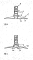
- the anchor consists of a single fluke 10, with a pair of terrafins 20, attached rigidly to the trailing edges of the fluke 26, and spaced apart by the fluke heel 18, so that the combined upper flat surfaces are entirety anhedral, together providing at least two flat anhedral surfaces symetrically about the medial plane, and a shank 11, of generally L-shape having a longer leg 11a, with the cable shackle point 12, and a shorter leg 11 b, to which is attached, in the same plane, a narrow flange 11 c, and a generally triangular shaped plate in a divergent plane to 11a, 11 and 11 c.
- the fluke 10, and Terrafins 20, are connected rigidly to the shank at the lower edges of 9, 11 b and 11 c, with the medial plane of the fluke and the medial plane of the shank coincident. This connection may be demountable.
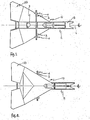
- the fluke is generally pentagonal in shape, with the forwardly swept cutting edges 17, converging at Angle D, which should lie in the range of 53° to 90°, with 60° being found to be optimum.
- Angle D has a re-entrant slot forming a pair of toes 21, on either side of the medial plane to facilitate rapid mooring bed penetration at mooring bed engagement
- the trailing edges of the fluke 26, are separated by the heel 18, which is normal to the medial plane, and are swept forward, forming Angle F, with 18, in the range 5° to 45°, with 17.5° being found to be optimum, to converge with the leading edges 17, at 15a
- the top fluke plate is folded anhedrally along 16, in the medial plane 14, providing two surfaces 15, on either side of the medial plane.
- the anhedral Angle E, at 16, lies in the range of 5° to 45° with the optimum being found to be 7.5°.
- flat triangular shaped Plate 10a is fixed to undersurfaces 10b, along edges 10c, to give the fluke rigidity, and the three mutually inclined flat surfaces provide high roll resistance.
- the angle of attack of the fluke Angle B should lie between 5° and 20°, with 10° being found to be optimum.
- the terrafins 20, should be generally quadrelateral in plan with the rear edge 28, greater in length than the edge adjoining the fluke at 26, and the outboard edge 27, should be be greater in length than the inboard edge attached to the shank at 9.
- the outer comer formed between 27 and 28 should be rounded or chamfered to facilitate the anchor rolling from any attitude other than fluke member lowermost to fluke member lowermost without the comer engaging the mooring bed.
- the ratio of area of a terrafin to the area of the upper surface of the fluke should fall in the range 0.125 to 0.6 with the optimum being found to be 0.3
- the anhedral angle between the terrafin and the fluke at Angle G, junction line 26, should lie between 5° and 30°, with 15° being found to be optimum.
- the shank consists of main lateral shank plates 7, parallel and symetrical to the medial plane, of generally L-shape and for practical purposes the ratio of 8 2 :8, should lie between 0.3 and 0.5, with 0.34 being found to be the optimum.
- Transverse shank Plate 8 connects and separates lateral shank Plates 7, and cable shackle point Plate 6, on the medial plane along with 5 No. rods or tubes 5, to provide rigidity, and a sixth rod or tubes joins and separates rigidly the divergent aft triangular portions of the shank 9.
- The'angle of divergence between 9 and 7, Angle C lies between 1 ° and 45° with the optimum angle found to be 17.5°.
- shank shackle point should lie on a straight line intersecting the fluke fold line 1 6, at the heel 18, at angle A, which should lie between 1 and 50° with 20° being found to be optimum.
- One of the shank plates 7, has an access hole 12a, for the shackle pin.
- Transverse shank plate 8 lies on a plane which intersects the fold line 16, in the medial plane 14, at an angle in the range of 0° and 30°, with 12.5° being found to be optimum.
- the two lateral shank plates can be, in thickness, between 0.042 and 0.083 times the separation between the plates and between 0.046 and 0.064 being found to be the optimum.
- the rod or tube diameters can be between 0.096 and 0.193 times the separation in plates 7, however between 0.125 and 0.130 has been found to be optimum.
- the rods or tubes are round in cross section since it has been found, by experiment, that a round cross section minimises the obstruction of disturbed mooring bed material passing between the shank plates and, unlike any flat section, it causes no lift to the shank, as there can be no angle of attack in the rods or tubes.
- the flat section, transverse shank plate 8 on the other hand is located ahead of the cable shackle point, and the shackle bow rebate in the leading edge forming a pair of toes similar to the toes 2 1 of the fluke, acts in undisturbed mooring bed material and experiences a high burial force under drag forces from the anchor cable.
- transverse shank plate having a low burial resistance, experiencing a high proportion of mooring cable force, in a high passive resistance of undisturbed mooring bed it helps to firmly locate the shank in a nose down attitude.
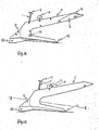
- the under surfaces of the terrafins 20, presented forward to the mooring bed, as shown in fig. 5, causes an upward moment to the rear of the fluke when the anchor is dragged forward by the mooring cable. That is, the transverse shank plate 8, and the terrafins together cause a moment couple producing a high burial component as the anchor is either dragged forward, or tended to be dragged forward, whether at commencement of burial or fully buried.
- the terrafins perform four separate functions in varying mooring bed materials and stages of operation.
- the first function is to tilt the fluke with a positive angle of attack when the anchor is at rest on a horizontal mooring bed so that the under surfaces of the terrafins 20, are presented forward and outboard of the fluke abeam extremities, and the fluke toes will engage the mooring bed if dragged forward by the mooring cable, whereby the cable force is generally horizontal in direction.
- the second function is as herein before described above in the moment couple with the transverse shank plate.
- the third function is for the upper surfaces to act as extended fluke surfaces when the anchor's angle of attack is high enough for the under surfaces of the terrafins to disappear in presentation forward to the mooring bed. This happens in mooring beds of low shear strength.
- the fourth function of the terrafins is to act as stabilisers in roll during burial and in a fully buried attitude, should some mooring bed disturbing force overcome the roll resistance of the three flat under surfaces mutually inclined and the anchor roll from medial plane verticaL
- the anchor of the present invention rolls generally about axis X-X,13, when under drag by the anchor mooring cable and the fluke is engaged or partially engaged in the mooring bed.
- This particular axis is not a pure roll axis, and whereby the anchor rotates or rolls about that axis there is a roll-yaw couple.
- the under surface of the lower terrafin is presented forward to the mooring bed, and if the angle of attack is shallow, the under surface of the upper terrafin will also be presented forward, but be of an apparently lesser area of presentation forward.
- the divergent aft shank plates 9 fulfil three functions
- the primary function is to present a large area forward, to the same side of the shank as the direction of cable veering, when the anchor is engaged in the mooring bed in a working attitude.
- the anchor will come under the influence of a moment couple, causing the anchor to veer until the cable and anchor medial planes are generally planar.
- shank plates 9 The second function of shank plates 9 is to present resistance areas forward to the mooring bed material in a plane other than that of the fluke, to adopt passive resistance of the mooring bed in a relatively undisturbed mooring bed area.
- the third function of the shank plates 9, is to allow mooring bed material between the lateral shank plates 7, to be easily released when weighing anchor.
- the anhedral form of fluke is found by experiment to be superior in rate of burial, holding power, roll stability, and structural integrity to either flat planar, or dihedral shaped flukes. This is due to the fact that for any given depth of anchor burial, the leading edges are reaching a deeper point in the shear strength gradient, and that anchors which are more difficult to roll can maintain higher holding power loads.
- the anhedral fluke form braced from below by plate 10a, makes a very light structure and therefore a very large fluke area can be used without a weight penalty in comparison with any other drag embedment anchor.
- the pennant cable can be attached to shank rods or tubes 5, at the shank plates 9, or the upper shank knee rod or pin, since the anchor centre of gravity 19, is very low and close to the fluke.
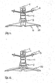
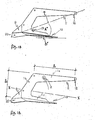
- the Bower anchor of this invention is identical in every respect to the mooring anchor as herein before described and illustrated in figs. 1 -6, but with at least one destabiliser bar attached to the upper rear portion of the shank.
- Transverse destabiliser bar or tube 3 is located generally adjacent to the upper edge of the shank lateral plates 7, generally above the midpoint of the fore and aft dimension of the fluke.
- the ends of the bar or tube 3 should overhang the fluke leading edges 17, symetrically at each side, outboard, by 10% to 20%, 15% optimum, the width of the fluke vertically below the bar3.
- discs or washers 4 should be attached to the bar at each end, generally the dimension of fluke overhang, inboard from the ends.
- the disc or washer should be of diameter 4 -6 times the diameter of the shank rods or tubes 5.
- Destabiliser bar 3 should be angled upward from the shank so that the bar or tube ends are generally level with or above the cable shackle point when the anchor fluke is set on a horizontal surface.
- destabiliser bars 1 and 3 have been found to require a diameter of 1.0 to 1.5 times the diameter of the shank rods or tubes 5.
- Destabiliser bar or tube 1 is attached generally vertically in the medial plane to the upper shank knee rod or tube and destabiliser bar of tube is raked forward until the free end is generally vertically above the centre of gravity of the anchor when the anchor is on a horizontal surface, fluke lowermost
- destabiliser bar or tube 1 should be between 0.3 and 0.4 times the length of destabiliser bar 3. Also destabiliser bar or tube 1, should be capped with a disc2, of similar diameter to disc 4, but preferably convex domed to prevent penetrative engagement with the mooring bed.
- the anchor After laying the anchor by the anchor cable, and should the anchor, in the unlikely event, come to rest on the mooring bed in an attitude other than fluke lowermost, then the anchor will have either the cap 2, of destabiliser bar 1, in contact with the mooring bed, or one of the ends of destabiliser bar 3, in contact with the mooring bed.
- a pull on the cable with a catinery will cause the anchor to roll from the former attitude to the latter attitude to fluke member lowermost, and the anchor will proceed to take up penetrative engagement with the mooring bed, toes first.
- Destabiliser bars or tubes 1 and 3 are round in cross section and when the anchor is fully buried, they operate in disturbed mooring bed material, and by experiment are found not to measurably alter the performance of the mooring anchor, herein before described and illustrated in figs 1-6.
- the Bower anchor of this invention is the same in all respects to the Bower anchor as illustrated in figs. 7-12 with the exception of minorfluke amendments, and the lateral shank plate 11 a, 11 b, and 11c, is a single plate construction without a transverse shank plate 8.
- the knee of the shank is raised to the equivelant. point of the centre of destabiliser bar 1, cap 2, and the shank drops forward to the shackle point end.
- the shackle point is in the same position ahead and above the fluke as in the Mooring anchor and Bower illustrated in figs. 1 -12.
- the destabiliser bar or tube 3 is symetrically located on the shank in generally the same level as the shackle point, at a point generally vertically above the mid point of the fore and aft dimension of the fluke.
- the destabiliser bar is the same as that in the Bower anchor in figs 7-12, except the bar or tube does not have to be raked upward from the shank, but can be straight from end to end and normal to the medial plane.
- the anchor of figs 13-18 behaves in the same way as the anchor of figs. 7-12, except the top of the shank knee fulfils the function of convex cap 2.
- an anchor of this invention constructed of mild steel, operating in a mooring bed of submerged loose sand and gravel of load bearing capacity of 65-110 KN/m 2 , with a catinery in the anchor cable, to consistently develop a holding power in excess of 120 times self weight force.
Landscapes
- Chemical & Material Sciences (AREA)
- Engineering & Computer Science (AREA)
- Combustion & Propulsion (AREA)
- Mechanical Engineering (AREA)
- Ocean & Marine Engineering (AREA)
- Piles And Underground Anchors (AREA)
Applications Claiming Priority (2)
| Application Number | Priority Date | Filing Date | Title |
|---|---|---|---|
| GB8505988 | 1985-03-08 | ||
| GB8505988A GB2171970A (en) | 1985-03-08 | 1985-03-08 | Drag embedment anchors |
Publications (2)
| Publication Number | Publication Date |
|---|---|
| EP0196801A2 true EP0196801A2 (de) | 1986-10-08 |
| EP0196801A3 EP0196801A3 (de) | 1987-02-04 |
Family
ID=10575645
Family Applications (1)
| Application Number | Title | Priority Date | Filing Date |
|---|---|---|---|
| EP86301672A Withdrawn EP0196801A3 (de) | 1985-03-08 | 1986-03-10 | Schleppanker zum Festmachen |
Country Status (2)
| Country | Link |
|---|---|
| EP (1) | EP0196801A3 (de) |
| GB (1) | GB2171970A (de) |
Cited By (4)
| Publication number | Priority date | Publication date | Assignee | Title |
|---|---|---|---|---|
| WO1992020569A1 (en) * | 1991-05-21 | 1992-11-26 | Brupat Limited | Improved marine anchor |
| USD347206S (en) | 1991-07-15 | 1994-05-24 | Glynwed Engineering, Ltd. | Anchor (bower and mooring) |
| WO2017074177A1 (en) * | 2015-10-27 | 2017-05-04 | Stevlos B.V. | Anchor with improved penetration properties |
| CN108849671A (zh) * | 2018-06-29 | 2018-11-23 | 合肥学院 | 一种具有多个锚板的深水网箱拖曳锚 |
Families Citing this family (3)
| Publication number | Priority date | Publication date | Assignee | Title |
|---|---|---|---|---|
| GB9125241D0 (en) * | 1991-11-27 | 1992-01-29 | Brupat Ltd | Drag embedment marine anchor |
| NL1000583C2 (nl) * | 1995-06-16 | 1996-12-17 | Vrijhof Ankers Beheer Bv | Ankervloei. |
| JP4678624B1 (ja) * | 2010-07-14 | 2011-04-27 | 義明 白輪地 | アンカー |
Family Cites Families (6)
| Publication number | Priority date | Publication date | Assignee | Title |
|---|---|---|---|---|
| GB574326A (en) * | 1943-10-11 | 1946-01-01 | Beckett Allan H | Improvements in and relating to anchors |
| NL6814828A (de) * | 1968-10-16 | 1970-04-20 | ||
| FR2366987A1 (fr) * | 1976-10-06 | 1978-05-05 | Colin Armand | Systeme d'ancres modulaire |
| GB2035242B (en) * | 1978-11-17 | 1983-04-13 | Smith R | Anchor |
| AU531505B2 (en) * | 1979-06-01 | 1983-08-25 | Peter Bruce | Anchors |
| US4433635A (en) * | 1980-11-19 | 1984-02-28 | Kyuroku Corporation | Single fluke anchor |
-
1985
- 1985-03-08 GB GB8505988A patent/GB2171970A/en not_active Withdrawn
-
1986
- 1986-03-10 EP EP86301672A patent/EP0196801A3/de not_active Withdrawn
Cited By (9)
| Publication number | Priority date | Publication date | Assignee | Title |
|---|---|---|---|---|
| WO1992020569A1 (en) * | 1991-05-21 | 1992-11-26 | Brupat Limited | Improved marine anchor |
| GB2271972A (en) * | 1991-05-21 | 1994-05-04 | Brupat Ltd | Improved marine anchor |
| GB2271972B (en) * | 1991-05-21 | 1995-09-27 | Brupat Ltd | Improved marine anchor |
| US5511506A (en) * | 1991-05-21 | 1996-04-30 | Brupat Limited | Marine anchor |
| USD347206S (en) | 1991-07-15 | 1994-05-24 | Glynwed Engineering, Ltd. | Anchor (bower and mooring) |
| WO2017074177A1 (en) * | 2015-10-27 | 2017-05-04 | Stevlos B.V. | Anchor with improved penetration properties |
| US10414467B2 (en) | 2015-10-27 | 2019-09-17 | Stevlos B.V. | Anchor with improved penetration properties |
| CN108849671A (zh) * | 2018-06-29 | 2018-11-23 | 合肥学院 | 一种具有多个锚板的深水网箱拖曳锚 |
| CN108849671B (zh) * | 2018-06-29 | 2024-04-02 | 合肥学院 | 一种具有多个锚板的深水网箱拖曳锚 |
Also Published As
| Publication number | Publication date |
|---|---|
| GB2171970A (en) | 1986-09-10 |
| GB8505988D0 (en) | 1985-04-11 |
| EP0196801A3 (de) | 1987-02-04 |
Similar Documents
| Publication | Publication Date | Title |
|---|---|---|
| US4397256A (en) | Anchors | |
| CA1172519A (en) | Anchor | |
| EP0425497B2 (de) | Schiffsanker | |
| EP0196801A2 (de) | Schleppanker zum Festmachen | |
| US4781142A (en) | High performance marine anchor | |
| US4831952A (en) | Anchor | |
| AU593016B2 (en) | Anchor | |
| KR20140074394A (ko) | 개량된 연안 해양 앵커 | |
| GB2035242A (en) | Anchor | |
| EP0180609B1 (de) | Apparat mit ankerschaufeln zum eingraben | |
| EP0670795B1 (de) | Ankerblatt | |
| US5511506A (en) | Marine anchor | |
| US3373712A (en) | Anchor having pivotable flukes | |
| US3766877A (en) | Mooring anchor | |
| US6332423B1 (en) | Marine anchor | |
| US20240043099A1 (en) | Mooring system | |
| US4397257A (en) | Sea anchor in particular for large ships | |
| US4134356A (en) | Anchors | |
| US2674969A (en) | Mooring anchor | |
| US2681631A (en) | Anchor | |
| AU734845B2 (en) | Anchor | |
| JPS60121183A (ja) | 錨構成体 | |
| NZ213126A (en) | Anchor with a flexible shank | |
| JP2003104281A (ja) | 舟艇用片爪アンカー | |
| JPH02158488A (ja) | 錨 |
Legal Events
| Date | Code | Title | Description |
|---|---|---|---|
| PUAI | Public reference made under article 153(3) epc to a published international application that has entered the european phase |
Free format text: ORIGINAL CODE: 0009012 |
|
| AK | Designated contracting states |
Kind code of ref document: A2 Designated state(s): AT BE CH DE FR GB IT LI LU NL SE |
|
| PUAL | Search report despatched |
Free format text: ORIGINAL CODE: 0009013 |
|
| AK | Designated contracting states |
Kind code of ref document: A3 Designated state(s): AT BE CH DE FR GB IT LI LU NL SE |
|
| 17P | Request for examination filed |
Effective date: 19870925 |
|
| 17Q | First examination report despatched |
Effective date: 19881012 |
|
| STAA | Information on the status of an ep patent application or granted ep patent |
Free format text: STATUS: THE APPLICATION IS DEEMED TO BE WITHDRAWN |
|
| 18D | Application deemed to be withdrawn |
Effective date: 19901003 |