EP0196684A1 - Air guiding mechanism for an open roof construction, and an open roof construction provided with this air guiding mechanism - Google Patents
Air guiding mechanism for an open roof construction, and an open roof construction provided with this air guiding mechanism Download PDFInfo
- Publication number
- EP0196684A1 EP0196684A1 EP86200161A EP86200161A EP0196684A1 EP 0196684 A1 EP0196684 A1 EP 0196684A1 EP 86200161 A EP86200161 A EP 86200161A EP 86200161 A EP86200161 A EP 86200161A EP 0196684 A1 EP0196684 A1 EP 0196684A1
- Authority
- EP
- European Patent Office
- Prior art keywords
- air guiding
- guiding mechanism
- strip
- stop
- mechanism according
- Prior art date
- Legal status (The legal status is an assumption and is not a legal conclusion. Google has not performed a legal analysis and makes no representation as to the accuracy of the status listed.)
- Granted
Links
- 238000010276 construction Methods 0.000 title claims abstract description 19
- 230000000903 blocking effect Effects 0.000 claims abstract description 35
- 230000006835 compression Effects 0.000 claims description 9
- 238000007906 compression Methods 0.000 claims description 9
- 238000009434 installation Methods 0.000 claims description 2
- 238000007789 sealing Methods 0.000 description 2
- 241000427213 Plukenetia conophora Species 0.000 description 1
- 238000006073 displacement reaction Methods 0.000 description 1
- 230000008719 thickening Effects 0.000 description 1
Images

Classifications
-
- B—PERFORMING OPERATIONS; TRANSPORTING
- B60—VEHICLES IN GENERAL
- B60J—WINDOWS, WINDSCREENS, NON-FIXED ROOFS, DOORS, OR SIMILAR DEVICES FOR VEHICLES; REMOVABLE EXTERNAL PROTECTIVE COVERINGS SPECIALLY ADAPTED FOR VEHICLES
- B60J7/00—Non-fixed roofs; Roofs with movable panels, e.g. rotary sunroofs
- B60J7/22—Wind deflectors for open roofs
Definitions
- Air guiding mechanism for an open roof construction, and an open roof construction provided with this air guiding mechanism Air guiding mechanism for an open roof construction, and an open roof construction provided with this air guiding mechanism
- the invention relates to an air guiding mechanism for an open roof construction with a sliding panel, for a vehicle, the mechanism comprising an air guiding strip, which can be fitted at the front edge of the roof opening, wherein the air guiding strip is displaced upwardly into an operative position by spring means when the panel is being opened and is brought to a rest position against the pressure of the spring means under the action of this panel when the panel is being closed, wherein the operative position of the air guiding strip is determined by a stop.
- the air guiding mechanism according to the invention is characterized in that the stop is provided on a blocking means, which is connected to the air guiding strip.
- the air guiding mechanism itself, has a stop, which is independent of the vehicle roof.
- the stop is adjustable.
- the operative position of the air guiding strip can very easily be adjusted to different vehicle roofs.
- the invention relates to an open roof construction provided with the air guiding mechanism described herinbefore.
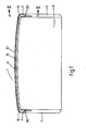
- the drawing illustrates an open roof construction for a vehicle, specifically an automobile, which is proivded with an air guiding mechanism.
- the fixed roof of the vehicle comprises an opening 2, which can be closed by means of a sliding panel 3.
- An air guiding strip 4 is fitted on the front side of the roof opening 2, this air guiding strip 4 comprising a central strip portion 5, which connects both sides by way of a bend 6 to a rearward bearing arm 7.
- the central strip portion 5 as well as the bends 6 and rearward bearing arms 7 are of a substantially rigid construction and have a groove 8 in their lower surface, in which a thickening 9 of an elastic sealing section 10 is accommodated.
- the bearing arms 7 are pivotally connected on their rear end to a gutter construction 11 of the open roof construction on both sides of the roof opening 2.
- a gutter construction 11 of the open roof construction on both sides of the roof opening 2.
- an U-shaped bearing section 12 is provided, of which the rear portion is connected to a pivot shaft 13.
- This pivot shaft 13 passes through the rear end of the respective bearing arm 7, so that the respective bearing arm 7 and thereby the whole air guiding strip 4 can pivot about this pivot shaft 13.
- Each bearing arm 7 is provided with a recess 14 at its lower side, which recess 14 partially accommodated the bearing section 12 and further a compression spring means 15 in the downwardly pivoted position of the air guiding strip 4.
- This compression means 15 comprises a compression spring 18, accommodated in telescopic bushes 16, 17.
- the lower bush 16 is pivotally connected to the front portion of the bearing section 12 by means of a transverse shaft 19.
- the upper bush 17 pivotally engages the bearing arm 7.near the front side thereof by means of a transverse shaft 20 provided in the respective bearing arm 7.
- the bearing section 12 is not only connected to the respective bearing arm 7 of the air guiding strip 4 through the pivot shaft 13 and the telescopic bushes 16, 17 but further also by means.of an adjustable blocking strip 21.
- this blocking strip 21 is provided with a stop 22, which can be locked in the direction of the blocking strip 21 by means of a counter stop 23 formed at the upper bush 17.
- This counter stop 23 further forms a guiding, which engages around an end portion of the blocking strip 21 provided with the stop 22 in such way that the upper bush 17 is only movable in the longitudinal direction of this end portion of the blocking strip 21.
- the blocking strip 21 has a slot 24 extending in the longitudinal direction of the vehicle, which slot 24 is gutted for a screw 25 which further passes through a slot 26 in the bearing section 12 and through a hole in the gutter construction 11, the screw 25 clamping the blocking strip 21 onto the bearing section 12 and the bearing section 12 onto the gutter construction 11 by means of a.nut 27 disposed underneath the gutter construction11.
- the slot 24 in the blocking strip 21 serves for adjusting the stop 22 formed on the blocking strip 21 and consequently for the height adjustment of the air guiding strip.4.
- the slot 26 in the bearing section 12 enables the air guiding strip 4 to be adjusted in the longitudinal direction of the gutter construction 11.
- a draw spring 29 engages the rear end 28 of the blocking strip 21., that lies at the side of the slot 24 and which is bent to an upwardly and backwardly inclined direction, the draw spring 29 being connected to the bearing section 12 at its other end and exerting a rearwardly directed tensive force onto the blocking strip 21.
- the purpose of this draw spring 29 will be elucidated hereinafter.
- the blocking strip 21 is flexible-and is guided between its ends around the lower end of the lower bush 16.
- Fig. 2 illustrates the panel 3 in its closed position, wherein a cam 30 provided on both sides underneath the panel 3 has come to engage on the respective bearing arm 7 of the air guiding strip 4 and has brought this into an downwardly pivoted position against the spring compression of the compression spring 18.
- the adjustment of the highest or operative position of the air guiding strip 4 can be carried out as follows:
- each draw spring 29 will keep the respective blocking strip 21 with its stop 22 in contact with the counter stop 23 of the upper bush 17, so that the slot 24 in the blocking-strip 21 moves backwardly with respect to the screw 25.
Landscapes
- Engineering & Computer Science (AREA)
- Mechanical Engineering (AREA)
- Seal Device For Vehicle (AREA)
- Specific Sealing Or Ventilating Devices For Doors And Windows (AREA)
Abstract
Description
- Air guiding mechanism for an open roof construction, and an open roof construction provided with this air guiding mechanism
- The invention relates to an air guiding mechanism for an open roof construction with a sliding panel, for a vehicle, the mechanism comprising an air guiding strip, which can be fitted at the front edge of the roof opening, wherein the air guiding strip is displaced upwardly into an operative position by spring means when the panel is being opened and is brought to a rest position against the pressure of the spring means under the action of this panel when the panel is being closed, wherein the operative position of the air guiding strip is determined by a stop.
- In a known embodiment of such an air guiding mechanism during the upward displacement of the air guiding strip it comes into engagement with a horizontal edge portion of the fixed roof at the front side of the roof opening, the edge portion thereby forming a stop for the air guiding strip and determining the operative position thereof.
- However, the problem arises that after installation of the open roof construction in the vehicle roof such edge portion is not always available, in which cases a stop for the air guiding strip is missing.
- It is an object of the present invention to provide an open roof construction, in which the above problem is effectively solved.
- To this end the air guiding mechanism according to the invention is characterized in that the stop is provided on a blocking means, which is connected to the air guiding strip.
- In this way the air guiding mechanism itself, has a stop, which is independent of the vehicle roof.
- Preferably the stop is adjustable. Hereby the operative position of the air guiding strip can very easily be adjusted to different vehicle roofs.
- Further the invention relates to an open roof construction provided with the air guiding mechanism described herinbefore.
- The invention will hereafter be elucidated with reference to the drawing, which shows an embodiment of an air guiding mechanism according to the invention by way of example.
- Fig. 1 is a schematic plan view of the opening in a vehicle roof in the fully opened position of the sliding panel, wherein the air guiding mechanism according to the invention can be seen.
- Fig. 2 is an enlarged section along the line II-II in fig. 1, partially broken away, wherein, however, the panel is in its closed position.
- Fig. 3 is a section corresponding to fig. 2, wherein the panel is, however, in its partially opened position.
- The drawing illustrates an open roof construction for a vehicle, specifically an automobile, which is proivded with an air guiding mechanism.
- The fixed roof of the vehicle comprises an
opening 2, which can be closed by means of asliding panel 3. An air guiding strip 4 is fitted on the front side of the roof opening 2, this air guiding strip 4 comprising acentral strip portion 5, which connects both sides by way of a bend 6 to a rearward bearingarm 7. - The
central strip portion 5 as well as the bends 6 and rearward bearingarms 7 are of a substantially rigid construction and have agroove 8 in their lower surface, in which athickening 9 of anelastic sealing section 10 is accommodated. - The bearing
arms 7 are pivotally connected on their rear end to agutter construction 11 of the open roof construction on both sides of the roof opening 2. To this end on each gutter,construction 11 an U-shaped bearingsection 12 is provided, of which the rear portion is connected to apivot shaft 13. Thispivot shaft 13 passes through the rear end of therespective bearing arm 7, so that therespective bearing arm 7 and thereby the whole air guiding strip 4 can pivot about thispivot shaft 13. Eachbearing arm 7 is provided with arecess 14 at its lower side, which recess 14 partially accommodated thebearing section 12 and further a compression spring means 15 in the downwardly pivoted position of the air guiding strip 4. - This compression means 15 comprises a
compression spring 18, accommodated intelescopic bushes lower bush 16 is pivotally connected to the front portion of thebearing section 12 by means of atransverse shaft 19. Theupper bush 17 pivotally engages the bearing arm 7.near the front side thereof by means of atransverse shaft 20 provided in therespective bearing arm 7. - ,The
bearing section 12 is not only connected to therespective bearing arm 7 of the air guiding strip 4 through thepivot shaft 13 and thetelescopic bushes adjustable blocking strip 21. At the side of the air guiding strip 4 thisblocking strip 21 is provided with astop 22, which can be locked in the direction of theblocking strip 21 by means of acounter stop 23 formed at theupper bush 17. This counter stop 23 further forms a guiding, which engages around an end portion of theblocking strip 21 provided with thestop 22 in such way that theupper bush 17 is only movable in the longitudinal direction of this end portion of theblocking strip 21. - At the side of the
bearing section 12 theblocking strip 21 has aslot 24 extending in the longitudinal direction of the vehicle, whichslot 24 is gutted for ascrew 25 which further passes through aslot 26 in thebearing section 12 and through a hole in thegutter construction 11, thescrew 25 clamping theblocking strip 21 onto thebearing section 12 and thebearing section 12 onto thegutter construction 11 by means of a.nut 27 disposed underneath the gutter construction11. - The
slot 24 in theblocking strip 21 serves for adjusting thestop 22 formed on theblocking strip 21 and consequently for the height adjustment of the air guiding strip.4. Theslot 26 in thebearing section 12 enables the air guiding strip 4 to be adjusted in the longitudinal direction of thegutter construction 11. - A
draw spring 29 engages therear end 28 of the blocking strip 21., that lies at the side of theslot 24 and which is bent to an upwardly and backwardly inclined direction, thedraw spring 29 being connected to thebearing section 12 at its other end and exerting a rearwardly directed tensive force onto theblocking strip 21. The purpose of thisdraw spring 29 will be elucidated hereinafter. - The
blocking strip 21 is flexible-and is guided between its ends around the lower end of thelower bush 16. - Fig. 2 illustrates the
panel 3 in its closed position, wherein acam 30 provided on both sides underneath thepanel 3 has come to engage on therespective bearing arm 7 of the air guiding strip 4 and has brought this into an downwardly pivoted position against the spring compression of thecompression spring 18. - In fig. 3 the panel has been slid backwardly, while the engagement of the-
cams 30 underneath thepanel 3 and the bearingarms 7 of the air guiding strip 4 has been released and thecompression springs 18 have been pivoted the air guiding strip 4 into a highest or operative position, which is determined by thestop 22 of theblocking strip 21. - The adjustment of the highest or operative position of the air guiding strip 4 can be carried out as follows:
- In an opened position of the
panel 3, as shown in fig. 3 thescrews 25, which can be reached through ahole 31 in therespective bearing arm 7 are turned loose. The compression springs 18 in thetelescopic bushes arms 7 pivot about thepivot shafts 13 until the rear ends of theslots 24 which move forwardly as a ,- consequence of the pivoting movement of theblocking strips 21 come into engagement with therespective screws 25. - In this position the air guiding strip 4 has reached its extreme outwardly pivoted position. During this pivoting movement the compressive force of the
compression springs 18 should exceed.the action of thedraw springs 29, so that thestops 22 of theblocking strips 21 can be carried along by thecounter stops 23. - When the air guiding strip 4 is hereafter moved downwardly, for instance by hand until the operative position thereof has been reached, each
draw spring 29 will keep therespective blocking strip 21 with itsstop 22 in contact with thecounter stop 23 of theupper bush 17, so that theslot 24 in the blocking-strip 21 moves backwardly with respect to thescrew 25. - When in the operative position the
screws 25 are tightened, so that theblocking strips 21 are clamped with respect to therespective bearing sections 12 the upward pivoting movement of the rear guiding strip 4 is limited up to this operative position. - In the working position the
elastic sealing section 10 joints to the vertical wall at the front side of the roof opening 2. - The invention is not restricted to the embodiment shown in the drawing by way of example, which can be varied in different ways within the scope of the invention.
Claims (14)
characterized in that the stop is adjustable.
characterized in that the blocking means can be adjustably mounted at one side and carries the stop at the other side, the stop co-operating with a counter stop.
characterized in that the blocking means includes a blocking strip.
characterized in that after installation thereof in the vehicle the blocking strip can be fixed with respect to the vehicle at the location of the slot.
Applications Claiming Priority (2)
| Application Number | Priority Date | Filing Date | Title |
|---|---|---|---|
| NL8500619A NL8500619A (en) | 1985-03-05 | 1985-03-05 | AIR CONDUCTION MECHANISM FOR AN OPEN ROOF CONSTRUCTION AND OPEN ROOF CONSTRUCTION EQUIPPED WITH THIS AIR CONDUCTION MECHANISM. |
| NL8500619 | 1985-03-05 |
Publications (2)
| Publication Number | Publication Date |
|---|---|
| EP0196684A1 true EP0196684A1 (en) | 1986-10-08 |
| EP0196684B1 EP0196684B1 (en) | 1988-06-01 |
Family
ID=19845630
Family Applications (1)
| Application Number | Title | Priority Date | Filing Date |
|---|---|---|---|
| EP86200161A Expired EP0196684B1 (en) | 1985-03-05 | 1986-02-05 | Air guiding mechanism for an open roof construction, and an open roof construction provided with this air guiding mechanism |
Country Status (4)
| Country | Link |
|---|---|
| US (1) | US4738483A (en) |
| EP (1) | EP0196684B1 (en) |
| DE (1) | DE3660243D1 (en) |
| NL (1) | NL8500619A (en) |
Cited By (7)
| Publication number | Priority date | Publication date | Assignee | Title |
|---|---|---|---|---|
| EP0385263A3 (en) * | 1989-03-03 | 1992-04-29 | Webasto AG Fahrzeugtechnik | Wind deflector for vehicle roofs with slidable cover |
| EP0716946A1 (en) * | 1994-12-15 | 1996-06-19 | Rockwell International GmbH | Wind deflector for vehicular sliding roof |
| DE19915544A1 (en) * | 1999-04-07 | 2000-10-12 | Volkswagen Ag | Wind deflection device for roof aperture of vehicle, with additional wind deflector running transversely behind main one |
| US6672657B2 (en) * | 2001-02-06 | 2004-01-06 | Webasto Vehicle Systems International Gmbh | Wind deflector for a motor vehicle |
| WO2010083789A1 (en) * | 2009-01-21 | 2010-07-29 | Webasto Ag | Wind deflector |
| EP3546261A4 (en) * | 2016-11-25 | 2020-07-08 | Yachiyo Industry Co., Ltd. | DEFLECTOR STRUCTURE FOR A SUNROOF DEVICE |
| WO2020225194A1 (en) * | 2019-05-09 | 2020-11-12 | Webasto SE | Vehicle roof having a wind deflector device |
Families Citing this family (9)
| Publication number | Priority date | Publication date | Assignee | Title |
|---|---|---|---|---|
| US6299245B1 (en) * | 1999-11-15 | 2001-10-09 | Honda Giken Kogyo Kabushiki Kaisha | Wind deflector and sunshade stopping system, and method of using same |
| DE19958748B4 (en) * | 1999-12-07 | 2005-07-28 | Webasto Ag | Device for influencing the air flow |
| DE10048983A1 (en) | 2000-09-27 | 2002-07-11 | Webasto Vehicle Sys Int Gmbh | Mechanics for a wind deflector of an openable vehicle roof |
| DE10143265C1 (en) * | 2001-09-04 | 2003-04-30 | Porsche Ag | Motor vehicle with a roof arrangement |
| DE10309395B3 (en) * | 2003-03-04 | 2004-10-28 | Daimlerchrysler Ag | sunroof assembly |
| DE102005002538B4 (en) * | 2005-01-19 | 2008-04-30 | Webasto Ag | vehicle roof |
| DE102005027450B4 (en) * | 2005-06-14 | 2008-11-06 | Webasto Ag | Wind deflector for a sunroof |
| JP2012081876A (en) * | 2010-10-12 | 2012-04-26 | Yachiyo Industry Co Ltd | Deflector of sunroof device |
| US10583725B1 (en) * | 2018-09-28 | 2020-03-10 | Nissan North America, Inc. | Vehicle wind deflector assembly |
Citations (7)
| Publication number | Priority date | Publication date | Assignee | Title |
|---|---|---|---|---|
| DE1149627B (en) * | 1959-10-20 | 1963-05-30 | H T Golde G M B H & Co K G | Swivel-mounted wind deflector on motor vehicles with a sliding roof |
| GB980012A (en) * | 1963-01-03 | 1965-01-13 | Weathershields Ltd | Improvements in vehicles having sliding roofs |
| DE1262135B (en) * | 1962-10-11 | 1968-02-29 | Franz Bruessow | Device for moving a wind deflector rotatably mounted on motor vehicles within the sunroof cutout |
| DE2100715A1 (en) * | 1970-01-10 | 1971-07-22 | Weathershields Ltd., Birmingham (Grossbritannien) | Draft deflector for vehicle sunroofs |
| FR2185037A1 (en) * | 1972-05-18 | 1973-12-28 | Weathershields Ltd | |
| DE2533516A1 (en) * | 1974-07-29 | 1976-06-16 | Vermeulen Hollandia B V | VEHICLE SUNROOF |
| FR2564787A1 (en) * | 1984-05-28 | 1985-11-29 | Weinsberg Karosseriewerke | Wind deflector flap for sliding roof panel |
Family Cites Families (3)
| Publication number | Priority date | Publication date | Assignee | Title |
|---|---|---|---|---|
| US1850229A (en) * | 1929-10-05 | 1932-03-22 | Concealed Door Check Company | Doorcheck |
| SU527310A1 (en) * | 1974-09-03 | 1976-09-05 | Головное Союзное Конструкторское Бюро По Автобусам Министерства Автомобильной Промышленности Ссср | Vehicle ventilation hatch |
| DE2937118A1 (en) * | 1979-09-13 | 1981-04-02 | Karosseriewerke Weinsberg Gmbh, 7102 Weinsberg | WIND / RAIN DEFLECTORS FOR VEHICLES WITH SLIDING ROOFS |
-
1985
- 1985-03-05 NL NL8500619A patent/NL8500619A/en not_active Application Discontinuation
-
1986
- 1986-02-05 EP EP86200161A patent/EP0196684B1/en not_active Expired
- 1986-02-05 DE DE8686200161T patent/DE3660243D1/en not_active Expired
- 1986-02-10 US US06/828,438 patent/US4738483A/en not_active Expired - Lifetime
Patent Citations (7)
| Publication number | Priority date | Publication date | Assignee | Title |
|---|---|---|---|---|
| DE1149627B (en) * | 1959-10-20 | 1963-05-30 | H T Golde G M B H & Co K G | Swivel-mounted wind deflector on motor vehicles with a sliding roof |
| DE1262135B (en) * | 1962-10-11 | 1968-02-29 | Franz Bruessow | Device for moving a wind deflector rotatably mounted on motor vehicles within the sunroof cutout |
| GB980012A (en) * | 1963-01-03 | 1965-01-13 | Weathershields Ltd | Improvements in vehicles having sliding roofs |
| DE2100715A1 (en) * | 1970-01-10 | 1971-07-22 | Weathershields Ltd., Birmingham (Grossbritannien) | Draft deflector for vehicle sunroofs |
| FR2185037A1 (en) * | 1972-05-18 | 1973-12-28 | Weathershields Ltd | |
| DE2533516A1 (en) * | 1974-07-29 | 1976-06-16 | Vermeulen Hollandia B V | VEHICLE SUNROOF |
| FR2564787A1 (en) * | 1984-05-28 | 1985-11-29 | Weinsberg Karosseriewerke | Wind deflector flap for sliding roof panel |
Cited By (11)
| Publication number | Priority date | Publication date | Assignee | Title |
|---|---|---|---|---|
| EP0385263A3 (en) * | 1989-03-03 | 1992-04-29 | Webasto AG Fahrzeugtechnik | Wind deflector for vehicle roofs with slidable cover |
| EP0716946A1 (en) * | 1994-12-15 | 1996-06-19 | Rockwell International GmbH | Wind deflector for vehicular sliding roof |
| DE19915544A1 (en) * | 1999-04-07 | 2000-10-12 | Volkswagen Ag | Wind deflection device for roof aperture of vehicle, with additional wind deflector running transversely behind main one |
| US6672657B2 (en) * | 2001-02-06 | 2004-01-06 | Webasto Vehicle Systems International Gmbh | Wind deflector for a motor vehicle |
| WO2010083789A1 (en) * | 2009-01-21 | 2010-07-29 | Webasto Ag | Wind deflector |
| CN102271945A (en) * | 2009-01-21 | 2011-12-07 | 韦巴斯托股份公司 | Wind deflector |
| US8246111B2 (en) | 2009-01-21 | 2012-08-21 | Webasto SE | Wind deflector |
| CN102271945B (en) * | 2009-01-21 | 2013-10-30 | 韦巴斯托股份公司 | Wind deflector |
| EP3546261A4 (en) * | 2016-11-25 | 2020-07-08 | Yachiyo Industry Co., Ltd. | DEFLECTOR STRUCTURE FOR A SUNROOF DEVICE |
| US11052738B2 (en) | 2016-11-25 | 2021-07-06 | Yachiyo Industry Co., Ltd. | Deflector structure for sunroof device |
| WO2020225194A1 (en) * | 2019-05-09 | 2020-11-12 | Webasto SE | Vehicle roof having a wind deflector device |
Also Published As
| Publication number | Publication date |
|---|---|
| EP0196684B1 (en) | 1988-06-01 |
| US4738483A (en) | 1988-04-19 |
| DE3660243D1 (en) | 1988-07-07 |
| NL8500619A (en) | 1986-10-01 |
Similar Documents
| Publication | Publication Date | Title |
|---|---|---|
| EP0196684A1 (en) | Air guiding mechanism for an open roof construction, and an open roof construction provided with this air guiding mechanism | |
| US4482183A (en) | Wind deflector device at an automobile roof | |
| CA1275844C (en) | Visor system | |
| CN100393541C (en) | car sunroof system | |
| EP0143475B1 (en) | Corkscrew device | |
| US5042556A (en) | Door assembly including a movable door with a flexible door panel | |
| US3984143A (en) | Open-roof construction for a vehicle | |
| GB2287743A (en) | Glass holder | |
| US4986598A (en) | Wind deflector for a sunroof | |
| GB2165194A (en) | A sliding and raisable roof | |
| US5069501A (en) | Spoiler sunroof control mechanism | |
| US4971387A (en) | Air guide device for an automobile roof | |
| US4221079A (en) | Window lifting arrangement for a curved window pane | |
| US4260188A (en) | Hoop arrangement for foldable tops of automotive vehicles | |
| US4299057A (en) | Window operating assembly | |
| US4623169A (en) | Clamp | |
| US4103962A (en) | Sliding roof for automobiles | |
| CA2231496C (en) | Adjustable shoe for awning window hinge | |
| ES281022U (en) | Spoiler roof | |
| CN212583483U (en) | Door system | |
| EP0242476A1 (en) | Hinge | |
| US6796157B2 (en) | Machine for forming cheek bends in sheet metal | |
| US4872636A (en) | Exterior mirror for a vehicle | |
| EP0244110A2 (en) | Opening roof for a motor vehicle | |
| GB2314050A (en) | Gutter support on a sliding-tilting roof. |
Legal Events
| Date | Code | Title | Description |
|---|---|---|---|
| PUAI | Public reference made under article 153(3) epc to a published international application that has entered the european phase |
Free format text: ORIGINAL CODE: 0009012 |
|
| AK | Designated contracting states |
Kind code of ref document: A1 Designated state(s): DE FR GB IT NL SE |
|
| 17P | Request for examination filed |
Effective date: 19860916 |
|
| 17Q | First examination report despatched |
Effective date: 19870326 |
|
| GRAA | (expected) grant |
Free format text: ORIGINAL CODE: 0009210 |
|
| AK | Designated contracting states |
Kind code of ref document: B1 Designated state(s): DE FR GB IT NL SE |
|
| REF | Corresponds to: |
Ref document number: 3660243 Country of ref document: DE Date of ref document: 19880707 |
|
| ITF | It: translation for a ep patent filed | ||
| ET | Fr: translation filed | ||
| PLBE | No opposition filed within time limit |
Free format text: ORIGINAL CODE: 0009261 |
|
| STAA | Information on the status of an ep patent application or granted ep patent |
Free format text: STATUS: NO OPPOSITION FILED WITHIN TIME LIMIT |
|
| 26N | No opposition filed | ||
| EAL | Se: european patent in force in sweden |
Ref document number: 86200161.7 |
|
| ITTA | It: last paid annual fee | ||
| REG | Reference to a national code |
Ref country code: GB Ref legal event code: IF02 |
|
| NLS | Nl: assignments of ep-patents |
Owner name: WEBASTOHOLLANDIA HOLDING B.V. |
|
| NLT1 | Nl: modifications of names registered in virtue of documents presented to the patent office pursuant to art. 16 a, paragraph 1 |
Owner name: WEBASTOHOLLANDIA OCTROOIEN B.V. Owner name: WEBASTO PRODUCT INTERNATIONAL NL B.V. |
|
| PGFP | Annual fee paid to national office [announced via postgrant information from national office to epo] |
Ref country code: FR Payment date: 20050124 Year of fee payment: 20 |
|
| PGFP | Annual fee paid to national office [announced via postgrant information from national office to epo] |
Ref country code: IT Payment date: 20050126 Year of fee payment: 20 |
|
| PGFP | Annual fee paid to national office [announced via postgrant information from national office to epo] |
Ref country code: GB Payment date: 20050202 Year of fee payment: 20 |
|
| PGFP | Annual fee paid to national office [announced via postgrant information from national office to epo] |
Ref country code: SE Payment date: 20050215 Year of fee payment: 20 |
|
| PGFP | Annual fee paid to national office [announced via postgrant information from national office to epo] |
Ref country code: NL Payment date: 20050228 Year of fee payment: 20 Ref country code: DE Payment date: 20050228 Year of fee payment: 20 |
|
| PG25 | Lapsed in a contracting state [announced via postgrant information from national office to epo] |
Ref country code: GB Free format text: LAPSE BECAUSE OF EXPIRATION OF PROTECTION Effective date: 20060204 |
|
| PG25 | Lapsed in a contracting state [announced via postgrant information from national office to epo] |
Ref country code: NL Free format text: LAPSE BECAUSE OF EXPIRATION OF PROTECTION Effective date: 20060205 |
|
| REG | Reference to a national code |
Ref country code: GB Ref legal event code: PE20 |
|
| NLV7 | Nl: ceased due to reaching the maximum lifetime of a patent |
Effective date: 20060205 |
|
| EUG | Se: european patent has lapsed |