EP0196285A2 - Fischzuchtbehälter - Google Patents
Fischzuchtbehälter Download PDFInfo
- Publication number
- EP0196285A2 EP0196285A2 EP86850063A EP86850063A EP0196285A2 EP 0196285 A2 EP0196285 A2 EP 0196285A2 EP 86850063 A EP86850063 A EP 86850063A EP 86850063 A EP86850063 A EP 86850063A EP 0196285 A2 EP0196285 A2 EP 0196285A2
- Authority
- EP
- European Patent Office
- Prior art keywords
- tank
- sludge
- water
- grooves
- funnel
- Prior art date
- Legal status (The legal status is an assumption and is not a legal conclusion. Google has not performed a legal analysis and makes no representation as to the accuracy of the status listed.)
- Granted
Links
- 241000251468 Actinopterygii Species 0.000 title claims abstract description 6
- XLYOFNOQVPJJNP-UHFFFAOYSA-N water Substances O XLYOFNOQVPJJNP-UHFFFAOYSA-N 0.000 claims abstract description 36
- 239000010802 sludge Substances 0.000 claims abstract description 31
- 239000002245 particle Substances 0.000 claims description 19
- 230000005489 elastic deformation Effects 0.000 claims description 3
- 238000010079 rubber tapping Methods 0.000 claims description 3
- 230000003014 reinforcing effect Effects 0.000 claims description 2
- 229920003023 plastic Polymers 0.000 claims 1
- 239000004033 plastic Substances 0.000 claims 1
- 230000002093 peripheral effect Effects 0.000 abstract 1
- 238000009372 pisciculture Methods 0.000 description 9
- 239000000356 contaminant Substances 0.000 description 8
- 230000000694 effects Effects 0.000 description 3
- 230000002787 reinforcement Effects 0.000 description 3
- 238000011010 flushing procedure Methods 0.000 description 2
- 239000013505 freshwater Substances 0.000 description 2
- 241000252073 Anguilliformes Species 0.000 description 1
- 230000015572 biosynthetic process Effects 0.000 description 1
- 238000004140 cleaning Methods 0.000 description 1
- 238000011109 contamination Methods 0.000 description 1
- 230000002349 favourable effect Effects 0.000 description 1
- 238000001914 filtration Methods 0.000 description 1
- 239000011521 glass Substances 0.000 description 1
- 238000007689 inspection Methods 0.000 description 1
- 238000004519 manufacturing process Methods 0.000 description 1
- 238000000034 method Methods 0.000 description 1
- 238000003860 storage Methods 0.000 description 1
- 239000002699 waste material Substances 0.000 description 1
Images

Classifications
-
- A—HUMAN NECESSITIES
- A01—AGRICULTURE; FORESTRY; ANIMAL HUSBANDRY; HUNTING; TRAPPING; FISHING
- A01K—ANIMAL HUSBANDRY; AVICULTURE; APICULTURE; PISCICULTURE; FISHING; REARING OR BREEDING ANIMALS, NOT OTHERWISE PROVIDED FOR; NEW BREEDS OF ANIMALS
- A01K63/00—Receptacles for live fish, e.g. aquaria; Terraria
- A01K63/04—Arrangements for treating water specially adapted to receptacles for live fish
-
- A—HUMAN NECESSITIES
- A01—AGRICULTURE; FORESTRY; ANIMAL HUSBANDRY; HUNTING; TRAPPING; FISHING
- A01K—ANIMAL HUSBANDRY; AVICULTURE; APICULTURE; PISCICULTURE; FISHING; REARING OR BREEDING ANIMALS, NOT OTHERWISE PROVIDED FOR; NEW BREEDS OF ANIMALS
- A01K61/00—Culture of aquatic animals
-
- A—HUMAN NECESSITIES
- A01—AGRICULTURE; FORESTRY; ANIMAL HUSBANDRY; HUNTING; TRAPPING; FISHING
- A01K—ANIMAL HUSBANDRY; AVICULTURE; APICULTURE; PISCICULTURE; FISHING; REARING OR BREEDING ANIMALS, NOT OTHERWISE PROVIDED FOR; NEW BREEDS OF ANIMALS
- A01K61/00—Culture of aquatic animals
- A01K61/10—Culture of aquatic animals of fish
-
- A—HUMAN NECESSITIES
- A01—AGRICULTURE; FORESTRY; ANIMAL HUSBANDRY; HUNTING; TRAPPING; FISHING
- A01K—ANIMAL HUSBANDRY; AVICULTURE; APICULTURE; PISCICULTURE; FISHING; REARING OR BREEDING ANIMALS, NOT OTHERWISE PROVIDED FOR; NEW BREEDS OF ANIMALS
- A01K63/00—Receptacles for live fish, e.g. aquaria; Terraria
- A01K63/10—Cleaning bottoms or walls of ponds or receptacles
-
- Y—GENERAL TAGGING OF NEW TECHNOLOGICAL DEVELOPMENTS; GENERAL TAGGING OF CROSS-SECTIONAL TECHNOLOGIES SPANNING OVER SEVERAL SECTIONS OF THE IPC; TECHNICAL SUBJECTS COVERED BY FORMER USPC CROSS-REFERENCE ART COLLECTIONS [XRACs] AND DIGESTS
- Y02—TECHNOLOGIES OR APPLICATIONS FOR MITIGATION OR ADAPTATION AGAINST CLIMATE CHANGE
- Y02A—TECHNOLOGIES FOR ADAPTATION TO CLIMATE CHANGE
- Y02A40/00—Adaptation technologies in agriculture, forestry, livestock or agroalimentary production
- Y02A40/80—Adaptation technologies in agriculture, forestry, livestock or agroalimentary production in fisheries management
- Y02A40/81—Aquaculture, e.g. of fish
Definitions
- the present invention relates to pisciculture, or more specifically to the type of culture involvinq the qrowinq of fish in a larqe number of separate tanks, which toqether form the pisciculture plant.
- the invention is thus not applicable to the type of pisciculture carried on in open-air basins, small lakes, secluded coastal inlets etc.
- the water in the tank is renewed by fresh water beinq introduced tanqential- ly at a point alonq the periphery of the tank and beinq allowed to circulate slowly towards a centrally situated outlet. From half to the whole of the water in the tank is replaced every hour, and the water level is kept constant in the tank.
- the tanks are qenerally open and may have a circular cross-sectional shape, which is the most favorable from the flow aspect, but due to reasons of space the tanks are most often formed square, with rounded corners, without the flow pattern beinq noticeably disturbed. Contaminants and dirt particles sink.to the bottom to form a bottom sludqe, which accompanies the circulatinq movement of the water while slowly movinq towards the centre, where it is tapped off.
- Pisciculture olant constructed accordinq to this principle i.e. made up from separate tanks, has been found to function excellently, but the known tanks used in such plants have been found nevertheless to have certain drawbacks, mainly two.
- the comparatively wide tanks must contain a larqe volume of water, their bottoms must be well supported, in other words they must stand on a proper floor. .
- the tanks could be arranqed in tiers in a simple lattice frame or beam system so that they could be stacked one above the other in a soace-savinq manner.
- the tanks used at present can not be placed on two beams arranged parallel, for example, without the water in the tank causing elastic deformation in it, which is troublesome to a great degree, particularly with regard to connecting the tank to fixed systems, where such elastic deformation can cause serious problems, and even the risk of rupture.
- the second drawback concerns the dirt and contaminants which gradually collect in the water and which form the mentioned bottom sludge. As mentioned,this only moves slowly towards a centrally placed outlet for tapping off, and it would be a great advantage if the residence time of the sludge in the tank could be considerably reduced, particularly since the radial movement of the sludge particles towards the centre for tapping off, caused by the slow circulation of the water, does not always correspond to new production of contaminants, which thus collect on the bottom and increase the amount of sludge. The necessary flushing then means a loss of water.
- the invention thus has the object of providing a new type of tank for pisciculture, in which the mentioned drawbacks are overcome, i.e. a tank which has the bottom stiffness required for being placed on a pair of beams in a shelf or storage system constructed to include such beams, the tank also being arranged so that the contaminants and dirt particles formed therein are quickly conveyed to the central outlet without any special flushing devices or the like being needed.
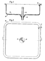
- FIG. 1 schematically illustrate how a pisciculture tank of known type is constructed, Fig 1 being a-cross section along the line I - I in Fig 2.
- FIGs 3 and 4 are schematic views respectively corresponding to Figs 1 and 2, but showing a pisciculture tank in accordance with the invention.
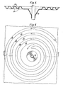
- Figs 5 and 6 illustrate to a larger scale the embodiment of the corrugations or ribs arranged at the bottom of the tank in accordance with the invention, Fig 5 being a cross section along the line V-V in Fig 6.
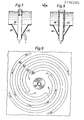
- Figs 6 and 7 schematically illustrate a central portion of the tank and show two different ways of removing the sludge,which is led in accordance with the invention to the centre of the tank.
- Fig 9 illustrates the flow pattern for the bottom sludge in an alternative bottom configuration in accordance with the invention.
- the conventional tank illustrated in Figs 1 and 2 has in horizontal cross section a substantially square shape, with rounded corners. It is supplied with fresh water via an inlet 12 disposed in one corner of it and directed tangentially along its wall. The water in the tank will thus circulate slowly, moving towards the centre of the tank, where an overflow 15 in the shape of an upstanding pipe is disposed, whereby the water level in the tank is kept constant. During the slow movement of the water, dirt particles and contaminants will sink to the bottom of the tank, where they form a sludge, as indicated at 16. This sludge rotates slowly with the water and moves simultaneously in towards the centre, where the tank is formed with a conical depression 18, in the centre of which the overflow pipe 15 is disposed. When sludge particles arrive at the centre of the tank they will thus be collected in the conical depression 18, from where they are removed, as will b6 described.
- the rather wide flat bottom of the tank means that it must be supported over the whole of its area by a flat carrying floor. Furthermore, the slow movement of the sludge towards the centre results in that sludge removal here does not keep pace with new formation of sludge, and the sludge layer over the bottom of the tank tends to grow.
- Figs 3 and 4 there is illustrated the implementation in accordance with the invention of the pisciculture tank 20, this tank corresponding in size and shape to the conventional tank in Figs 1 and 2.
- the bottom thereof has been reinforced by strong ribs or "corrugations" 25, extending over the bottom around the centre of the tank to form a strong reinforcement of the bottom, to such a high degree that a tank full of water may be supported on a pair of parallel beams without the tank being subject to disturbing deformations.
- the inventive tank 20 is provided with a wide edge flange 22, which contributes to a high degree in increasing the general stiffness of the tank, and its ability to withstand deformations.
- the flange 22 also extends a small distance in over the tank itself, which has a special effect, apart from increasing the stiffness of the edge without encroaching on the space outside the ordinary edge flange 22' of the tank, this effect namely being to prevent wriggling fish such as eels from getting over the edge of the tank.
- the bottom ribs 25, applied in accordance with the invention are disposed in a particular configuration. which has a surprising and highly advantageous effect on the movement of the particles and contaminants sinking to the bottom of the tank to form sludge.
- a single rib is formed, instead of several ribs, this rib having been laid in a spiral around the centre of the tank, to extend a plurality of turns , in this case about three complete turns.
- the sludge particles sinking towards the bottom will thus collect in the depressions between the rib turns, and obviously will thus be urged by the rib configuration towards the centre.
- the particles arriving at the conical sludge funnel at the centre of the circulatory course may be removed from the funnel in different ways.
- a simple alternative is illustrated schematically in Fig 7, where a funnel 30 with overflow 35 is disposed substantially as already described. At a point situated low on the funnel there is a smaller tapping-off pipe 32, and since the sludge is now quickly and effectively taken to the funnel and concentrated there,the sludge may be removed together with a very small amount of water. In actual fact, only about 10% of the total amount of water passing through the overflow pipe 35 passes out in this way.
- Fig 8 another alternative for removing the sludge, which is not subjected to any special concentration in the sludge funnel 40, but is directly and continuously taken off together with the departing water.
- an overflow pipe 45 as before, but it is now surrounded by an outer tubular sleeve 46, which opens out at a somewhat higher level than the overflow pipe, while the sleeve downwardly terminates shortly before the wall of the funnel 40 to form with the wall a narrow gap.
- the sludge is not concentrated, but continuously accompanies the departing water, which will maintain a substantially constant, low content of contaminants, which may be readily removed by suitable filtering and cleaning measures.
- a single cohesive guide rib is arranged in the bottom of the tank, where the rib extends spirally from the outside and inwards at a gradient adjusted so that there are three turns to the spiral.
- Fig 9 there is schematically shown how four spiral ribs 50,52,54,56 may be arranged mutually spaced but of similar configuration such that the system of guide ribs is given four inputs or starts. In this case a dirt particle sinking in the outer portion of the bottom is caused to move towards the central area containing the funnel 60, while merely passing along approximately one turn.
- bottom rib system may be given optimum configuration all according to operational conditions such as water circulation rate, nature of dirt and contamination particles and their mass etc.
- the nub of the invention resides in the stated proposal that in an extremely simple way and with simple means to facilitate the solution of the problem present in all fish cultivation of controlling and removing the contaminants and waste products formed, namely by creating, so to speak, a short cut for these products in their movement towards an outlet, so that they do not accompany the slowly circulating water and accumulate in it. Instead, they are urged, as soon as they have sunk to the bottom, to enter into a tighter path under the action of the circulating water, which leads to the centrally situated outlet.
Landscapes
- Life Sciences & Earth Sciences (AREA)
- Environmental Sciences (AREA)
- Marine Sciences & Fisheries (AREA)
- Animal Husbandry (AREA)
- Biodiversity & Conservation Biology (AREA)
- Zoology (AREA)
- Farming Of Fish And Shellfish (AREA)
Applications Claiming Priority (2)
| Application Number | Priority Date | Filing Date | Title |
|---|---|---|---|
| SE8500975A SE442576B (sv) | 1985-02-27 | 1985-02-27 | Kar for odling av levande fisk vars botten har spiralformade spar atskilda av likaledes spiralformade ribbor och varvid sparen mynnar i en slamsamlande fordjupning |
| SE8500975 | 1985-02-27 |
Publications (3)
| Publication Number | Publication Date |
|---|---|
| EP0196285A2 true EP0196285A2 (de) | 1986-10-01 |
| EP0196285A3 EP0196285A3 (en) | 1987-04-01 |
| EP0196285B1 EP0196285B1 (de) | 1990-08-29 |
Family
ID=20359301
Family Applications (1)
| Application Number | Title | Priority Date | Filing Date |
|---|---|---|---|
| EP86850063A Expired - Lifetime EP0196285B1 (de) | 1985-02-27 | 1986-02-21 | Fischzuchtbehälter |
Country Status (8)
| Country | Link |
|---|---|
| US (1) | US4655169A (de) |
| EP (1) | EP0196285B1 (de) |
| CA (1) | CA1238249A (de) |
| DE (1) | DE3673673D1 (de) |
| DK (1) | DK88286A (de) |
| FI (1) | FI860833A7 (de) |
| NO (1) | NO860540L (de) |
| SE (1) | SE442576B (de) |
Cited By (5)
| Publication number | Priority date | Publication date | Assignee | Title |
|---|---|---|---|---|
| FR2622971A1 (fr) * | 1987-11-10 | 1989-05-12 | Cerisy Sa | Dispositif de comptage d'elements discrets en suspension dans un milieu fluide |
| EP1781091A4 (de) * | 2004-05-11 | 2008-04-30 | O K Technologies Llc | System zum anheben von wassertieren |
| WO2010127238A1 (en) * | 2009-05-01 | 2010-11-04 | Liqui-Box Corporation | Improvement in fill-accuracy during pouch formation |
| WO2017108060A1 (en) * | 2015-12-23 | 2017-06-29 | Nkt Photonics A/S | Photonic crystal fiber assembly |
| NO20220935A1 (en) * | 2021-12-10 | 2023-06-12 | Eide Fjordbruk As | A submersible fish rearing tank adapted to separate sludge from water and a method of operating such a tank |
Families Citing this family (15)
| Publication number | Priority date | Publication date | Assignee | Title |
|---|---|---|---|---|
| US4825527A (en) * | 1988-01-25 | 1989-05-02 | Multifastener Corporation | Method of attaching an element to a panel |
| ES2123051T5 (es) * | 1992-06-01 | 2002-11-16 | Sinvent As | Separador de particulas. |
| NO175341C (no) * | 1992-07-20 | 1994-10-05 | Geir L Kjersem | Fremgangsmåte ved tilförsel av vann til en lukket merd, utforming av en lukket merd og anvendelse av merden til utövelse av fremgangsmåte |
| US6093320A (en) * | 1998-11-30 | 2000-07-25 | Future Sea Technologies Inc | Tank cleaning system |
| US6443100B1 (en) | 2001-02-05 | 2002-09-03 | Future Sea Technologies Inc. | Debris separating system for fish pens |
| US20080017125A1 (en) * | 2006-06-22 | 2008-01-24 | Power Robert M | Culture tank for marine organisms |
| CA2763722C (en) * | 2009-06-17 | 2016-05-03 | Atlantech Engineering & Associates Incorporated | Triple drain apparatus for an aquaculture recirculation system |
| CA2780691C (en) * | 2012-06-26 | 2021-10-26 | Agrimarine Industries Inc. | Aquaculture rearing enclosure and circulation induction system |
| USD703798S1 (en) | 2013-03-11 | 2014-04-29 | Kohler Co. | Sink |
| USD703800S1 (en) | 2013-03-11 | 2014-04-29 | Kohler Co. | Sink |
| USD703799S1 (en) | 2013-03-11 | 2014-04-29 | Kohler Co. | Sink |
| USD703801S1 (en) | 2013-03-11 | 2014-04-29 | Kohler Co. | Sink |
| USD708721S1 (en) | 2013-09-10 | 2014-07-08 | Kohler Co. | Sink |
| USD713515S1 (en) | 2013-09-10 | 2014-09-16 | Kohler Co. | Sink |
| NO346521B1 (no) * | 2019-03-15 | 2022-09-19 | Seafarming Systems As | Oppdrettsmerd med forbedret vannutskifting og framgangsmåte for å oppnå dette |
Family Cites Families (4)
| Publication number | Priority date | Publication date | Assignee | Title |
|---|---|---|---|---|
| US1528179A (en) * | 1923-08-13 | 1925-03-03 | Henry L Baldridge | Fish-hatchery pond |
| US3116712A (en) * | 1962-10-19 | 1964-01-07 | Hubert S Ogden | Closed cycle fish rearing system |
| US4211183A (en) * | 1977-08-08 | 1980-07-08 | Hoult David P | Fish raising |
| GB1594832A (en) * | 1978-02-23 | 1981-08-05 | Goodson M G | Aquaculture tank |
-
1985
- 1985-02-27 SE SE8500975A patent/SE442576B/sv not_active IP Right Cessation
-
1986
- 1986-02-14 NO NO860540A patent/NO860540L/no unknown
- 1986-02-21 EP EP86850063A patent/EP0196285B1/de not_active Expired - Lifetime
- 1986-02-21 DE DE8686850063T patent/DE3673673D1/de not_active Expired - Lifetime
- 1986-02-25 US US06/833,645 patent/US4655169A/en not_active Expired - Fee Related
- 1986-02-26 FI FI860833A patent/FI860833A7/fi not_active Application Discontinuation
- 1986-02-26 DK DK88286A patent/DK88286A/da unknown
- 1986-02-26 CA CA000502796A patent/CA1238249A/en not_active Expired
Cited By (8)
| Publication number | Priority date | Publication date | Assignee | Title |
|---|---|---|---|---|
| FR2622971A1 (fr) * | 1987-11-10 | 1989-05-12 | Cerisy Sa | Dispositif de comptage d'elements discrets en suspension dans un milieu fluide |
| WO1989004118A1 (fr) * | 1987-11-10 | 1989-05-18 | Cerisy S.A. | Dispositif de comptage d'elements discrets en suspension dans un milieu fluide |
| EP1781091A4 (de) * | 2004-05-11 | 2008-04-30 | O K Technologies Llc | System zum anheben von wassertieren |
| WO2010127238A1 (en) * | 2009-05-01 | 2010-11-04 | Liqui-Box Corporation | Improvement in fill-accuracy during pouch formation |
| US10059475B2 (en) | 2009-05-01 | 2018-08-28 | Liqui-Box Corporation | Fill-accuracy during pouch formation |
| WO2017108060A1 (en) * | 2015-12-23 | 2017-06-29 | Nkt Photonics A/S | Photonic crystal fiber assembly |
| NO20220935A1 (en) * | 2021-12-10 | 2023-06-12 | Eide Fjordbruk As | A submersible fish rearing tank adapted to separate sludge from water and a method of operating such a tank |
| NO348043B1 (en) * | 2021-12-10 | 2024-07-08 | Eide Fjordbruk As | A submersible fish rearing tank adapted to separate sludge from water and a method of operating such a tank |
Also Published As
| Publication number | Publication date |
|---|---|
| EP0196285A3 (en) | 1987-04-01 |
| DE3673673D1 (de) | 1990-10-04 |
| NO860540L (no) | 1986-08-28 |
| FI860833A0 (fi) | 1986-02-26 |
| SE442576B (sv) | 1986-01-20 |
| EP0196285B1 (de) | 1990-08-29 |
| FI860833L (fi) | 1986-08-28 |
| DK88286A (da) | 1986-08-28 |
| CA1238249A (en) | 1988-06-21 |
| FI860833A7 (fi) | 1986-08-28 |
| DK88286D0 (da) | 1986-02-26 |
| US4655169A (en) | 1987-04-07 |
| SE8500975D0 (sv) | 1985-02-27 |
Similar Documents
| Publication | Publication Date | Title |
|---|---|---|
| EP0196285B1 (de) | Fischzuchtbehälter | |
| US6932025B2 (en) | Scalable fish rearing raceway system | |
| US5232586A (en) | Floating media hourglass biofilter | |
| CN104705238B (zh) | 一种水生动物养殖系统 | |
| WO2006000042A1 (en) | Aquaculture system | |
| KR20170067254A (ko) | 슬러지 제거용 트랩과 침전조가 형성된 바이오플락시스템 | |
| CA3004215A1 (en) | System for selective waste removal from an aquaculture unit | |
| WO2011136660A1 (en) | Farming system for aquatic organisms | |
| CN106942121A (zh) | 一种养殖池 | |
| KR102065570B1 (ko) | 다층 구조 어류 사육용 수조 | |
| CN104365514B (zh) | 一种鳗鱼工厂化养殖系统 | |
| KR101317854B1 (ko) | 녹조 제어용 천적생물 배양을 위한 플랑크톤 배양장치 | |
| KR101703897B1 (ko) | 육상 양식용 수조 | |
| KR101580435B1 (ko) | 트랩을 이용한 바이오플락 시스템 양식수조의 슬러지 제어 장치 | |
| AU678020B2 (en) | A clarifier for the separation of solids in waste water | |
| KR101877363B1 (ko) | 3중 구조 생물 여과조 | |
| CN109122545A (zh) | 一种池塘底排污水质改良系统 | |
| CN220654476U (zh) | 一种新型养殖排污装置 | |
| CN219950665U (zh) | 一种水产养殖循环水净化装置 | |
| WO2018163096A1 (en) | Bioreaktor | |
| KR101634710B1 (ko) | 플랑크톤 배양장치 | |
| KR102878055B1 (ko) | 여과기능을 갖는 유수식 양식장용 폴리에틸렌 융착식 산소용해장치 | |
| CN222024195U (zh) | 一种鱼池污水处理装置 | |
| JP4755767B2 (ja) | 養殖池等の水槽 | |
| DE10106255A1 (de) | Trennelemente in Hälterungsbecken zur Intensivierung der Produktion von Garnelen und des mikrobiellen Abbaus von Schmutzstoffen |
Legal Events
| Date | Code | Title | Description |
|---|---|---|---|
| PUAI | Public reference made under article 153(3) epc to a published international application that has entered the european phase |
Free format text: ORIGINAL CODE: 0009012 |
|
| AK | Designated contracting states |
Kind code of ref document: A2 Designated state(s): DE FR GB IT |
|
| PUAL | Search report despatched |
Free format text: ORIGINAL CODE: 0009013 |
|
| AK | Designated contracting states |
Kind code of ref document: A3 Designated state(s): DE FR GB IT |
|
| 17P | Request for examination filed |
Effective date: 19871125 |
|
| RAP1 | Party data changed (applicant data changed or rights of an application transferred) |
Owner name: PULLOLA, ARVO |
|
| RIN1 | Information on inventor provided before grant (corrected) |
Inventor name: PULLOLA, ARVO |
|
| 17Q | First examination report despatched |
Effective date: 19900207 |
|
| GRAA | (expected) grant |
Free format text: ORIGINAL CODE: 0009210 |
|
| AK | Designated contracting states |
Kind code of ref document: B1 Designated state(s): DE FR GB IT |
|
| REF | Corresponds to: |
Ref document number: 3673673 Country of ref document: DE Date of ref document: 19901004 |
|
| ITF | It: translation for a ep patent filed | ||
| ET | Fr: translation filed | ||
| PLBE | No opposition filed within time limit |
Free format text: ORIGINAL CODE: 0009261 |
|
| STAA | Information on the status of an ep patent application or granted ep patent |
Free format text: STATUS: NO OPPOSITION FILED WITHIN TIME LIMIT |
|
| 26N | No opposition filed | ||
| PGFP | Annual fee paid to national office [announced via postgrant information from national office to epo] |
Ref country code: GB Payment date: 19920124 Year of fee payment: 7 |
|
| PGFP | Annual fee paid to national office [announced via postgrant information from national office to epo] |
Ref country code: FR Payment date: 19920218 Year of fee payment: 7 |
|
| PGFP | Annual fee paid to national office [announced via postgrant information from national office to epo] |
Ref country code: DE Payment date: 19920222 Year of fee payment: 7 |
|
| PG25 | Lapsed in a contracting state [announced via postgrant information from national office to epo] |
Ref country code: GB Effective date: 19930221 |
|
| GBPC | Gb: european patent ceased through non-payment of renewal fee |
Effective date: 19930221 |
|
| PG25 | Lapsed in a contracting state [announced via postgrant information from national office to epo] |
Ref country code: FR Effective date: 19931029 |
|
| PG25 | Lapsed in a contracting state [announced via postgrant information from national office to epo] |
Ref country code: DE Effective date: 19931103 |
|
| REG | Reference to a national code |
Ref country code: FR Ref legal event code: ST |
|
| PG25 | Lapsed in a contracting state [announced via postgrant information from national office to epo] |
Ref country code: IT Free format text: LAPSE BECAUSE OF NON-PAYMENT OF DUE FEES;WARNING: LAPSES OF ITALIAN PATENTS WITH EFFECTIVE DATE BEFORE 2007 MAY HAVE OCCURRED AT ANY TIME BEFORE 2007. THE CORRECT EFFECTIVE DATE MAY BE DIFFERENT FROM THE ONE RECORDED. Effective date: 20050221 |