EP0195903A2 - Plattenförmiges Heizelement, insbesondere für Fussbodenheizungen - Google Patents
Plattenförmiges Heizelement, insbesondere für Fussbodenheizungen Download PDFInfo
- Publication number
- EP0195903A2 EP0195903A2 EP86101479A EP86101479A EP0195903A2 EP 0195903 A2 EP0195903 A2 EP 0195903A2 EP 86101479 A EP86101479 A EP 86101479A EP 86101479 A EP86101479 A EP 86101479A EP 0195903 A2 EP0195903 A2 EP 0195903A2
- Authority
- EP
- European Patent Office
- Prior art keywords
- heating element
- spacer elements
- elements
- heating
- straight line
- Prior art date
- Legal status (The legal status is an assumption and is not a legal conclusion. Google has not performed a legal analysis and makes no representation as to the accuracy of the status listed.)
- Granted
Links
Images

Classifications
-
- F—MECHANICAL ENGINEERING; LIGHTING; HEATING; WEAPONS; BLASTING
- F24—HEATING; RANGES; VENTILATING
- F24D—DOMESTIC- OR SPACE-HEATING SYSTEMS, e.g. CENTRAL HEATING SYSTEMS; DOMESTIC HOT-WATER SUPPLY SYSTEMS; ELEMENTS OR COMPONENTS THEREFOR
- F24D3/00—Hot-water central heating systems
- F24D3/12—Tube and panel arrangements for ceiling, wall, or underfloor heating
- F24D3/14—Tube and panel arrangements for ceiling, wall, or underfloor heating incorporated in a ceiling, wall or floor
- F24D3/141—Tube mountings specially adapted therefor
- F24D3/142—Tube mountings specially adapted therefor integrated in prefab construction elements
-
- Y—GENERAL TAGGING OF NEW TECHNOLOGICAL DEVELOPMENTS; GENERAL TAGGING OF CROSS-SECTIONAL TECHNOLOGIES SPANNING OVER SEVERAL SECTIONS OF THE IPC; TECHNICAL SUBJECTS COVERED BY FORMER USPC CROSS-REFERENCE ART COLLECTIONS [XRACs] AND DIGESTS
- Y02—TECHNOLOGIES OR APPLICATIONS FOR MITIGATION OR ADAPTATION AGAINST CLIMATE CHANGE
- Y02B—CLIMATE CHANGE MITIGATION TECHNOLOGIES RELATED TO BUILDINGS, e.g. HOUSING, HOUSE APPLIANCES OR RELATED END-USER APPLICATIONS
- Y02B30/00—Energy efficient heating, ventilation or air conditioning [HVAC]
Definitions
- the invention relates to a plate-shaped heating element, in particular for underfloor heating, according to the preamble of patent claim 1.
- Plate-shaped heating elements which consist of two plates lying parallel to one another and spacing elements arranged between the plates, are known from DE-OS 30 32 694.
- Such heating elements are preferably made of thermoelastic plastic and require the spacer elements as support elements between the upper and lower plate in order to absorb the forces acting on the heating elements in the case of underfloor heating.
- such heating elements are to be designed so that they absorb the static internal pressure generated by the heating medium.
- Such heating elements are also used for wall and ceiling heating as well as for cooling purposes, which is why in all cases the most uniform possible full flow of the entire cavity lying between the two plates should be ensured.
- the invention has for its object to provide a heating element of the type mentioned, which ensures as uniform as possible, full-area flow through the cavity between the upper and lower plate.
- the dynamic cross-section of each individual heating element is a multiple of the respective connection cross-section, as a result of which the water velocity changes by one after the heating medium (or cooling medium) enters the heating element Reduced many times and often at least in regions hardly any more flow speeds can be achieved that correspond to a directed flow.
- the configuration or arrangement of the spacer elements according to the invention achieves a very precise division of the heating medium, for example water, after it has entered the heating element.
- the resistance per heating element is exactly defined by the arrangement of the spacer elements in a predetermined pattern.
- connection elements which are approximately diametrically opposed to one another in the case of a plate-shaped heating element, there is no continuous "channel" which contains the main flow, but that such a continuous "channel” due to the offset arrangement of the spacer elements is prevented. Seen from the axis of the connecting element, this means that the spacing elements are offset from one another and thereby ensure a distribution of the medium flowing through the heating element over the entire cavity.
- the heating element can preferably be used for underfloor heating, it can also be used as wall and ceiling heating and for cooling purposes.
- Fig. 1 shows a horizontal sectional view of a plate-shaped heating element, which consists of an upper and lower plate.
- the upper and lower plates are connected to one another by spacer elements, a cavity being defined between the two plates, the cavity being interspersed with the spacer elements in a manner to be described below.
- the heating element has two connecting elements 1, 2 which are essentially diametrically opposite one another, preferably in the form of tubular connecting pieces. Between the two connection elements 1, 2 there are rows substantially perpendicular to one another in the plane of the drawing, i.e. vertical and horizontal rows with spacer elements, some of which are designated by the reference numerals 3, 4, 5 and 6.
- the flow of the heating medium running in the inlet-side connection element 1 is designated by 7.
- the heating medium for example water, thus strikes a first row of spacer elements 3, 4, .5 after it has passed through the connecting element 1 and is deflected in the lateral direction by these spacer elements. This ensures a flow of the cavity of the heating element in the lateral direction, as the arrows in Fig. 1 illustrate, thus preventing a direct channel between the connection elements 1, 2, i.e. a free flow, which would be possible if along the in Fig. 1 with 8 designated line would have no spacer elements.
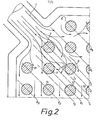
- FIG. 2 illustrates the principle according to the invention of the arrangement of the individual spacer elements.
- G is the extension of the central axis of the tubular connecting element 1.
- the first spacer element 3 is thus centered on the straight line G opposite the connecting element 1.
- spacing elements are provided at a distance from one another in the same way as explained with reference to the straight line G.
- the straight line g 1 include spacer elements 11, 12, on the line 2 g, inter alia, spacer elements 13, 14, etc. provided.
- the view according to FIG. 2 shows that the offset arrangement of spacer elements corresponding to the straight lines G, g 1 to g5 etc. leads to the heating medium not only flowing through the heating element along a channel, but practically the entire cavity of the heating element as a result of the deflection of the heating medium to the most distant side areas of the heating element.
- the arrangement of the spacer elements - with respect to the input-side connection element - is such that a first row with spacer elements is formed, which lies in the extension of the central axis of the connection element 1 and that further rows parallel thereto on both sides the straight line G is present.
- the heating element thus has a multiplicity of rows with spacer elements, the rows each lying parallel to one another and parallel to the axis of the connecting elements 1, 2.
- the arrangement of the spacer elements corresponds exactly to that as explained with reference to FIG. 2.
- the spacer elements are provided while maintaining essentially constant distances from one another along the rows represented by the straight lines.
- the spacer elements 3, 13 along the straight line G, G 2 for their part, lie next to one another while maintaining a predetermined distance, ie the pattern has further rows of spacer elements lying perpendicular to the straight line G, G 1 etc.
- the spacer elements 3, 6, etc. along the straight line G form tangents T 1 , T 2 , and accordingly the spacer elements along the straight line g 1 form tangents T 3 , T 4 , etc.
- the resistance and flow conditions in the individual heating elements are optimally obtained regardless of the size of each heating element by the arrangement of the spacer elements described, and that a flow through the entire cavity of the heating element is ensured both with large and small heating elements can be obtained without the risk of channel formation.
- the flows illustrated by the arrows 15 to 17 in FIG. 1 result from channels remaining in the vertical direction and bring about the complete flow through the heating element even into the most lateral corner regions of the heating element; these flows are returned to the connecting element 2, as the arrows in the area of the connecting element 2 show.
- These "channels" contribute to a good distribution of the individual water flows in the heating element and are the result of the arrangement of the spacer elements 3 to 5 with the associated rows at the inlet of the heating medium in the area of the connecting element 1.
- the spacer 4 and thus the straight line G are arranged centrally on the connecting element 1 and that there is no free passage between the two connecting elements 1, 2, i.e. between the flow and the return of the heating medium.
- the spacer elements have the function of baffles and, with their different sizes or different diameters, allow the desired flow cross-section to be defined and thus a minimum flow velocity to be defined in the entire heating element.
- the heating element thus has a plurality of rows of spacers which are parallel to the axis of the connection elements, while at the same time in the vertical and horizontal directions, i.e. at an angle of approximately 45 ° to the extension of the axis of the connecting elements, channels remain free which contribute to the lateral flow of the heating element.
- FIG. 3 shows a sectional view along the line III-III in FIG. 1.
- the reference elements 20, 21, 22 show the spacing elements in the cutting line, while 24, 25, 26 indicate a part of the free spaces remaining between the spacing elements .
- the upper plate of the heating element is designated 30, the plate below 31. Laterally, the two plates are firmly connected to each other and thus result in the cavity through which the heating medium flows.
- the flow rate of the medium within the heating plate is defined at the maximum volume flow given the known maximum permissible speed in the connecting lines.
- the speed in the heating plate should not fall below 0.1 m / sec in order to ensure that there are still directed currents in the heating plate.
- the mass flows for the individual heating plates can be calculated on the basis of the load conditions which can be defined relatively precisely by the building physics and the limit values of comfort.
- the area cross-section ratio should not exceed 1: 4.
- the ratio 1: 3.5 should not be exceeded. It has been shown that a reduction in the cross-sectional ratio up to limit values of 1: 3.5 is advantageous for both heating and cooling plates. If the surface cross-sectional ratio of 1: 3 is determined by the arrangement of the knobs, the flow rate becomes higher and improves heat transfer within each plate directly related to flow velocity.
Landscapes
- Engineering & Computer Science (AREA)
- Physics & Mathematics (AREA)
- Thermal Sciences (AREA)
- Chemical & Material Sciences (AREA)
- Combustion & Propulsion (AREA)
- Mechanical Engineering (AREA)
- General Engineering & Computer Science (AREA)
- Central Heating Systems (AREA)
- Steam Or Hot-Water Central Heating Systems (AREA)
- Resistance Heating (AREA)
- Surface Heating Bodies (AREA)
Abstract
Description
- Die Erfindung betrifft ein plattenförmiges Heizelement, insbesondere für Fußbodenheizungen, gemäß dem Oberbegriff des Patentanspruchs 1.
- Plattenförmige Heizelemente, die aus zwei parallel zueinander liegenden Platten und zwischen den Platten angeordneten Abstandselementen bestehen, sind aus der DE-OS 30 32 694 bekannt.
- Derartige Heizelemente werden vorzugsweise aus thermoelastischem Kunststoff hergestellt und erfordern die Abstandselemente als Stützelemente zwischen der oberen und unteren Platte, um die im Falle einer Fußbodenheizung auf die Heizelemente wirkenden Kräfte aufzunehmen. Außerdem sind derartige Heizelemente derart stabil auszubilden, daß sie den vom Heizmedium erzeugten statischen Innendruck aufnehmen.
- Derartige Heizelemente werden auch für Wand- und Deckenheizungen sowie für Kühlzwecke verwendet, weshalb in jedem Falle eine möglichst gleichmäßige, vollflächige Durchströmung des gesamten, zwischen den beiden Platten liegenden Hohlraumes sichergestellt sein soll.
- Der Erfindung liegt die Aufgabe zugrunde, ein Heizelement der eingangs genannten Art zu schaffen, das eine möglichst gleichmäßige, vollflächige Durchströmung des Hohlraumes zwischen der oberen und unteren Platte sicherstellt.
- Diese Aufgabe wird erfindungsgemäß durch den kennzeichnenden Teil des Patentanspruchs 1 gelöst.
- Weitere Ausgestaltungen der Erfindung ergeben sich aus den Unteransprüchen.
- Die durchschnittliche Wassergeschwindigkeit in Heizungsanlagen liegt aufgrund verschiedener technischer Erfordernisse bei v = 1,2 m/sec. Dieser Wert stellt die üblicherweise höchste Wassergeschwindigkeit in den Anschlußbögen und Verbindungleitungen dar, die mithin nicht überschritten werden darf. Der dynamische Querschnitt jedes einzelnen Heizelementes beträgt jedoch ein Vielfaches des jeweiligen Anschlußquerschnittes, infolgedessen sich die Wassergeschwindigkeit nach dem Eintritt des Heizmediums (oder Kühlmediums) in das Heizelement um ein Vielfaches verringert und häufig zumindest bereichsweise kaum mehr Strömungsgeschwindigkeiten erreicht werden, die einer gerichteten Strömung entsprechen. Durch die erfindungsgemäße Ausbildung bzw. Anordnung der Abstandselemente wird eine sehr genaue Aufteilung des Heizmediums, beispielsweise Wasser, nach dem Eintritt in das Heizelement erreicht. Ferner wird der Widerstand pro Heizelement durch die Anordnung der Abstandselemente in einem vorbestimmten Muster exakt definiert. Bei dem Heizelement wird insbesondere sichergestellt, daß zwischen den Anschlußelementen, die bei einem Heizelement plattenförmiger Gestalt etwa diametral einander gegenüber liegen, kein durchgehender "Kanal" vorliegt, der die Hauptströmung beinhaltet, sondern daß durch die versetzte Anordnung der Abstandselemente ein solcher durchgehender "Kanal" verhindert wird. Aus der Achse des Anschlußelementes gesehen, bedeutet dies, daß die Abstandselemente zueinander versetzt liegen und dadurch eine Verteilung des das Heizelement durchströmenden Mediums über den gesamten Hohlraum sicherstellen.
- Obgleich das Heizelemente vorzugsweise für Fußbodenheizungen anwendbar ist, läßt es sich auch als Wand- und Deckenheizung sowie für Kühlzwecke einsetzen.
- Im folgenden wird das plattenförmige Heizelement an Hand der Zeichnung zur Erläuterung weiterer Merkmale beschrieben.
- Es zeigen:
- Fig. 1 eine horizontale Schnittansicht durch ein Heizelement,
- Fig. 2 eine horizontale Teilschnittansicht des Heizelementes nach Fig. 1 zur Erläuterung der Strömungsverhältnisse, und
- Fig. 3 eine vertikale Schnittansicht durch das Heizelement nach . Fig. 1 entlang der Linie III - III.
- Fig. 1 zeigt eine horizontale Schnittansicht auf ein plattenförmiges Heizelement, das aus einer oberen und unteren Platte besteht. Die obere und untere Platte sind durch Abstandselemente miteinander verbunden, wobei zwischen den beiden Platten ein Hohlraum festgelegt ist, der in noch zu beschreibender Weise mit den Abstandelementen durchsetzt ist.
- Nach Fig. 1 weist das Heizelement zwei im wesentlichen diametral zueinander liegende Anschlußelemente 1, 2 vorzugsweise in Form von rohrförmigen Anschlußstutzen auf. Zwischen den beiden Anschlußelementen 1, 2 sind in der Zeichenebene im wesentlichen zueinander senkrechte Reihen,d.h.vertikale und horizontale Reihen mit Abstandselementen vorgesehen, von denen einige Abstandselemente mit dem Bezugszeichen 3,4,5 und 6 bezeichnet sind. Mit 7 ist die im eingangsseitigen Anschlußelement 1 verlaufende Strömung des Heizmediums bezeichnet. Das Heizmedium, beispielsweise Wasser, trifft somit nach seinem Durchtritt durch das Anschlußelement 1 auf eine erste Reihe von Abstandselementen 3, 4, .5 auf und wird durch diese Abstandselemente in seitlicher Richtung abgelenkt. Dadurch wird ein Durchfluß des Hohlraumes des Heizelementes in seitlicher Richtung gewährleistet, wie die Pfeile in Fig. 1 verdeutlichen, somit ein direkter Kanal zwischen den Anschlußelementen 1, 2, also ein freier Durchfluß verhindert, der dann möglich wäre, wenn entlang der in Fig. 1 mit 8 bezeichneten Linie keine Abstandselemente vorhanden wären.
- Die Teilansicht in Fig. 2 verdeutlicht das erfindungsgemäße Prinzip der Anordnung der einzelnen Abstandselemente. In Fig. 2 ist mit G die Verlängerung der Mittelachse des rohrförmigen Anschlußelementes 1 bezeichnet. Auf der Geraden G liegt somit mittig demAnschlußelement 1 gegenüber das erste Abstandselement 3. Weiterhin liegen auf der Geraden G hinter dem Abstandselement 3 weitere Abstandselemente 6, 10 usw.
- Auf den zur Geraden G parallelen Geraden g1, g 2' g 3' g 4 usw. sind in gleicher Weise wie unter Bezugnahme auf die Gerade G erläutert Abstandselemente in Abstand zueinander vorgesehen. Auf der Geraden g1 sind unter anderem Abstandselemente 11, 12, auf der Geraden g2 unter anderem Abstandselemente 13, 14 usw. vorgesehen. Entsprechendes gilt für die Abstandselemente auf den Geraden g4, g5. Die Ansicht nach Fig. 2 zeigt, daß die versetzte Anordnung von Abstandselementen entsprechend den Geraden G, g1 bis g5 usw. dazu führt, daß das Heizmedium das Heizelement nicht nur entlang eines Kanales durchströmt, sondern praktisch den gesamten Hohlraum des Heizelementes infolge der Ablenkung des Heizmediums bis in die entferntesten seitlichen Bereiche des Heizelementes.
- Bei der in Fig. 2 gezeigten Ausführungsform ist die Anordnung der Abstandselemente - in Bezug auf das eingangsseitige Anschlußelement - derart getroffen, daß eine erste Reihe mit Abstandselementen gebildet ist, die in der Verlängerung der Mittelachse des Anschlußelementes 1 liegt und daß weitere dazu parallele Reihen beidseitig der Geraden G vorhanden sind. Damit weist das Heizelement eine Vielzahl von Reihen mit Abstandselementen auf, wobei die Reihen jeweils parallel zueinander und parallel zur Achse der Anschlußelemente 1, 2 liegen. An der Seite des Anschlußelementes 2 entspricht die Anordnung der Abstandselemente genau derjenigen, wie sie unter Bezugnahme auf Fig. 2 erläutert ist.
- Die Abstandselemente sind, wie Fig. 2 zeigt, unter Einhaltung im wesentlichen konstanter Abstände zueinander entlang der durch die Geraden dargestellten Reihen vorgesehen. Die Abstandselemente 3, 13 entlang der Geraden G, G2, liegen ihrerseits unter Einhaltung eines vorgegebenen Abstandes nebeneinander, d.h. das Muster weist senkrecht zu den Geraden G, G1 usw. liegende weitere Reihen von Abstandselementen auf.
- Die Abstandselemente 3, 6 usw. entlang der Geraden G bilden Tangenten T1, T2, entsprechend bilden die Abstandselemente entlang der Geraden g1 Tangenten T3, T4 usw. Entsprechend dem gewünscinten Strömungsquerschnitt wird der Abstand zwischen einander benachbarten Tangenten, z. B. T1, T4 gewählt; dieser Abstand entspricht bei der dargestellten Ausführungsform etwa dem halben Durchmesser der Abstandselemente, und kann abhängig von dem jeweils erwünschten Querschnitt zur Erhöhung des Strömungswiderstandes bis 0 reduziert werden; in letzterem Falle fällt z. B. die Tangente T1 mit der Tangente T4 zusammen.
- Besonders vorteilhaft ist, daß durch die beschriebene Anordnung der Abstandselemente die Widerstands- und Strömungsverhältnisse in den einzelenen Heizelementen unabhängig von der Größe jedes Heizelementes in optimaler Weise erhalten werden, und daß sowohl bei großen wie auch bei kleinen Heizelementen eine Durchströmung des gesamten Hohlraumes des Heizelementes sichergestellt ist ohne die Gefahr einer Kanalbildung zu erhalten. Die in Fig. 1 durch die Pfeile 15 bis 17 veranschaulichten Strömungen ergeben sich durch in Vertikalrichtung verbleibende Kanäle und bewirken die völlständige Durchströmung des Heizelementes auch bis in die seitlichsten Eckbereiche des Heizelementes; diese Strömungen werden zum Anschlußelement 2 zurückgeführt, wie die Pfeile im Bereich des Anschlußelementes 2 zeigen. Diese "Kanäle" tragen zu einer guten Verteilung der einzelnen Wasserströme in dem Heizelement bei und sind Ergebnis der Anordnung der Abstandselemente 3 bis 5 mit den zugehörigen Reihen am Eintritt des Heizmediums im Bereich des Anschlußelementes 1.
- Gemäß vorstehenden Ausführungen ist es wesentlich, daß das Abstandselement 4 und somit die Gerade G mittig am Anschlußelement 1 angeordnet sind und zwischen den beiden Anschlußelementen 1, 2, d.h.zwischen dem Vorlauf und dem Rücklauf dem Heizmedium kein freier Durchgang möglich ist.
- Die Abstandselemente haben die Funktion von Schikanen und ermöglichen durch unterschiedliche Größe bzw. unterschiedlichen Durchmesser die Festlegung des gewünschten Strömungsquerschnittes und damit die Festlegung einer Mindestfließgeschwindigkeit im gesamten Heizelement.
- Bei dem Heizelement nach Fig. 1 und 2 liegt im Bereich des Anschlußelementes 1 die höchste Fließgeschwindigkeit vor, die sich in das Heizelement 1 hinein verringert unter Beibehaltung einer geringen Wassergeschwindigkeit in allen Bereichen der Heizplatte, während sich die Wassergeschwindigkeit zum Anschlußelement 2 wiederum vergrößerte
- Das Heizelement weist somit eine Vielzahl von Reihen mit Abstandselementen auf, die parallel zur Achse derAnschlußelemente liegen, während gleichzeitig in senkrechter und horizontaler Richtung, d.h. in einem Winkel von etwa 45 ° zur Verlängerung der Achse der Anschlußelemente Kanäle freibleiben, welche zur seitlichen Durchströmung des Heizelementes beitragen.
- Fig. 3 zeigt eine Schnittansicht entlang der Linie III - III in Fig. 1. Mit dem Bezugszeichen 20, 21, 22 sind die Abstandselemente in der Schnittlinie dargestellt, während mit 24, 25, 26 ein Teil der zwischen den Abstandselementen verbleibenden Freiräume angegeben sind. Die obere Platte des Heizelementes ist mit 30, die unter Platte mit 31 bezeichnet. Seitlich sind die beiden Platten fest miteinander verbunden und ergeben auf diese Weise den vom Heizmedium durchflossenen Hohlraum.
- Wie aus Fig. 1 ersichtlich ist, setzt sich die in Verbindung mit Fig. 2 beschriebene Anordnung von Abstandselementen über den gesamten Hohlraum bis zum gegenüberliegenden Anschlußelement 2 fort.
- Durch die Festlegung des Verhältnisses des Flächenquerschnitts in den Anschluß- oder Verbindungsleitungen gegenüber dem Flächenquerschnitt in der Heizplatte wird bei maximal gegebenem Volumenstrom auf Grund der bekannten maximal zulässigen Geschwindigkeit in den Anschlußleitungen die Strömungsgeschwindigkeit des Mediums innerhalb der Heizplatte definiert. Die Geschwindigkeit in der Heizplatte soll 0,1 m/sec nicht unterschreiten, um zu gewährleisten, daß in der Heizplatte noch gerichtete Strömungen herrschen. Durch die Anordnung der ersten, quer zur Strömungsrichtung aus der Anschlußleitung in die Heizplatte liegenden Reihe von Noppen wird ein freies Ausströmung des Mediums vom Querschnitt der Anschlußleitung in den Querschnitt der Heizplatte verhindert, wodurch sich die Stoßverluste nach Carnot-Bordasch Pv = P1 - P2 und damit Druckverluste vermindern.
- In der Heizungstechnik sind auf Grund der durch die bauphysikalischen Gegebenheiten und durch die Grenzwerte der Behaglichkeit relativ genau definierbaren Lastzustände die Massenströme für die einzelnen Heizplatten errechenbar. Das Flächenquerschittsverhältnis soll 1 : 4 nicht übersteigen.
- Bei Einsatz der Heizplatten als Wärmetauscher bei Kühlvorgängen soll aus dem selben Grund das Verhältnis 1 : 3,5 nicht überschritten werden. Es hat sich gezeigt, daß eine Verkleinerung des Querschnittsverhältnisses bis zu Grenzwerten von 1 : 3,5 sowohl bei Heiz- als auch bei Kühlplatten vorteilhaft ist.- Wird durch die Anordnung der Noppen ein Flächenquerschnittsverhältnis von 1 : 3 festgelegt, wird die Strömungsgeschindigkeit höher und die unmittelbar mit der Strömungsgeschwindigkeit zusammenhängenden Wärmeübertragungen innerhalb jeder Platte verbessert.
Claims (7)
dadurch gekennzeichnet ,
daß die Abstandselemente (3, 4, 5, 6, 10, usw.) derart angeordnet sind, daß sie eine erste Reihe entlang einer ersten Geraden (G) bilden, wobei die erste Gerade (G) einer Verlängerung der Achse des Anschlußelementes (1) entspricht, und
daß alle anderen Abstandselemente weitere Reihen von Abstandselementen bilden, die entlang von Geraden (g1, g 2 usw.) liegen, welche ihrerseits parallel zur ersten Geraden (G) liegen.
Priority Applications (1)
| Application Number | Priority Date | Filing Date | Title |
|---|---|---|---|
| AT86101479T ATE55001T1 (de) | 1985-03-19 | 1986-02-05 | Plattenfoermiges heizelement, insbesondere fuer fussbodenheizungen. |
Applications Claiming Priority (2)
| Application Number | Priority Date | Filing Date | Title |
|---|---|---|---|
| DE19853509895 DE3509895A1 (de) | 1985-03-19 | 1985-03-19 | Plattenfoermiges heizelement, insbesondere fuer fussbodenheizungen |
| DE3509895 | 1985-03-19 |
Publications (3)
| Publication Number | Publication Date |
|---|---|
| EP0195903A2 true EP0195903A2 (de) | 1986-10-01 |
| EP0195903A3 EP0195903A3 (en) | 1987-09-09 |
| EP0195903B1 EP0195903B1 (de) | 1990-07-25 |
Family
ID=6265698
Family Applications (1)
| Application Number | Title | Priority Date | Filing Date |
|---|---|---|---|
| EP86101479A Expired - Lifetime EP0195903B1 (de) | 1985-03-19 | 1986-02-05 | Plattenförmiges Heizelement, insbesondere für Fussbodenheizungen |
Country Status (3)
| Country | Link |
|---|---|
| EP (1) | EP0195903B1 (de) |
| AT (1) | ATE55001T1 (de) |
| DE (2) | DE3509895A1 (de) |
Cited By (1)
| Publication number | Priority date | Publication date | Assignee | Title |
|---|---|---|---|---|
| EP1760408A2 (de) | 2005-09-06 | 2007-03-07 | R.B.M. S.P.A. | Wärmeabstrahlende Platte, insbesondere für Heiz- und/oder Klimasysteme |
Families Citing this family (3)
| Publication number | Priority date | Publication date | Assignee | Title |
|---|---|---|---|---|
| US5080166A (en) * | 1987-04-15 | 1992-01-14 | Itrag Ag | Plate-shaped heating element, in particular for floor heating |
| DE9109213U1 (de) * | 1991-07-25 | 1992-11-19 | Bossert, Gerdi, 7730 Villingen-Schwenningen | Plattenelement |
| DE4240252A1 (en) * | 1991-12-02 | 1993-08-05 | Iduso Gmbh | Sandwich channelled ceramic plate - has glazing between plates with same thermal expansion as the plate clay for bonding during firing |
Family Cites Families (6)
| Publication number | Priority date | Publication date | Assignee | Title |
|---|---|---|---|---|
| US4184543A (en) * | 1976-07-06 | 1980-01-22 | Olin Corporation | Heat exchanger exhibiting improved mechanical and thermal stability |
| DE3032694C2 (de) * | 1980-08-29 | 1987-02-12 | ZUGLA AG, Glarus | Plattenförmiges Heiz- und/oder Kühlelement |
| DE3331981A1 (de) * | 1983-09-05 | 1985-03-21 | ZUGLA AG, Glarus | Verbindungsstueck, insbesondere zum fluessigkeitsdichten verbinden zweier anschluesse von heizplatten einer fussbodenheizung |
| DE8403592U1 (de) * | 1984-02-08 | 1984-06-28 | Wand, geb. Hanssmann, Isolde, 5410 Höhr-Grenzhausen | Flaechenheizelementenbahn |
| DE8429708U1 (de) * | 1984-07-18 | 1985-02-07 | Kurt Hirsch Kunststoffwerk Gesellschaft mbH, Glanegg | Montageplatte fuer fussbodenheizungen |
| FR2575279B1 (fr) * | 1984-12-21 | 1989-07-07 | Barriquand | Echangeur a plaques |
-
1985
- 1985-03-19 DE DE19853509895 patent/DE3509895A1/de active Granted
-
1986
- 1986-02-05 EP EP86101479A patent/EP0195903B1/de not_active Expired - Lifetime
- 1986-02-05 AT AT86101479T patent/ATE55001T1/de not_active IP Right Cessation
- 1986-02-05 DE DE8686101479T patent/DE3672859D1/de not_active Expired - Fee Related
Cited By (1)
| Publication number | Priority date | Publication date | Assignee | Title |
|---|---|---|---|---|
| EP1760408A2 (de) | 2005-09-06 | 2007-03-07 | R.B.M. S.P.A. | Wärmeabstrahlende Platte, insbesondere für Heiz- und/oder Klimasysteme |
Also Published As
| Publication number | Publication date |
|---|---|
| DE3672859D1 (de) | 1990-08-30 |
| DE3509895A1 (de) | 1986-09-25 |
| ATE55001T1 (de) | 1990-08-15 |
| DE3509895C2 (de) | 1989-08-10 |
| EP0195903B1 (de) | 1990-07-25 |
| EP0195903A3 (en) | 1987-09-09 |
Similar Documents
| Publication | Publication Date | Title |
|---|---|---|
| DE69422207T2 (de) | Plattenwärmetauscher und entsprechende Platten | |
| DE69208822T2 (de) | Wärmesenke mit Stiften und Strömungsverbesserung | |
| DE69614402T2 (de) | Plattenwärmetauscher | |
| DE2441652C3 (de) | Rippenrohr-Wärmetauscher | |
| EP0529422B1 (de) | Einbaukörper | |
| DE10118625B4 (de) | Wellenförmige Lamelle mit Versatz für Plattenwärmetauscher | |
| DE19819248C1 (de) | Flachrohr eines Heizungswärmetauschers oder Kühlers eines Kraftfahrzeugs | |
| EP2150765B1 (de) | Strömungskanal für einen mischer-wärmetauscher | |
| DE60022572T2 (de) | Verdampfer | |
| EP2045556A2 (de) | Plattenwärmetauscher | |
| DE2248273A1 (de) | Waermeaustauscher und verfahren zu dessen anwendung | |
| DE19709601C5 (de) | Plattenwärmeübertrager | |
| DE69508892T2 (de) | Plattenstapel für einen Wärmetauscher | |
| DE3734857C2 (de) | ||
| EP0195903B1 (de) | Plattenförmiges Heizelement, insbesondere für Fussbodenheizungen | |
| AT393162B (de) | Plattenwaermeaustauscher mit besonderem profil der waermeaustauschzone | |
| DE202017102436U1 (de) | Wärmetauscher mit Mikrokanal-Struktur oder Flügelrohr-Struktur | |
| EP0361225A1 (de) | Füllkörper | |
| DE3032694C2 (de) | Plattenförmiges Heiz- und/oder Kühlelement | |
| EP1540662B1 (de) | Abstandhalter | |
| DE2428042B2 (de) | Roehrenwaermeaustauscher | |
| DE2534445A1 (de) | Gegenstromwaermeaustauscher | |
| CH649373A5 (de) | Waermetauscher. | |
| DE2831639C2 (de) | Plattenbatterie für Stoff- und Wärmetauscher sowie für Tropfenabscheider | |
| WO1999067591A1 (de) | Plattenwärmetauscher |
Legal Events
| Date | Code | Title | Description |
|---|---|---|---|
| PUAI | Public reference made under article 153(3) epc to a published international application that has entered the european phase |
Free format text: ORIGINAL CODE: 0009012 |
|
| AK | Designated contracting states |
Kind code of ref document: A2 Designated state(s): AT BE CH DE FR GB IT LI LU NL SE |
|
| PUAL | Search report despatched |
Free format text: ORIGINAL CODE: 0009013 |
|
| AK | Designated contracting states |
Kind code of ref document: A3 Designated state(s): AT BE CH DE FR GB IT LI LU NL SE |
|
| RHK1 | Main classification (correction) |
Ipc: F24D 3/16 |
|
| 17P | Request for examination filed |
Effective date: 19871028 |
|
| 17Q | First examination report despatched |
Effective date: 19880704 |
|
| RAP1 | Party data changed (applicant data changed or rights of an application transferred) |
Owner name: ITRAG AG |
|
| GRAA | (expected) grant |
Free format text: ORIGINAL CODE: 0009210 |
|
| AK | Designated contracting states |
Kind code of ref document: B1 Designated state(s): AT BE CH DE FR GB IT LI LU NL SE |
|
| REF | Corresponds to: |
Ref document number: 55001 Country of ref document: AT Date of ref document: 19900815 Kind code of ref document: T |
|
| ET | Fr: translation filed | ||
| GBT | Gb: translation of ep patent filed (gb section 77(6)(a)/1977) | ||
| REF | Corresponds to: |
Ref document number: 3672859 Country of ref document: DE Date of ref document: 19900830 |
|
| ITF | It: translation for a ep patent filed | ||
| PG25 | Lapsed in a contracting state [announced via postgrant information from national office to epo] |
Ref country code: LU Free format text: LAPSE BECAUSE OF NON-PAYMENT OF DUE FEES Effective date: 19910228 |
|
| PLBE | No opposition filed within time limit |
Free format text: ORIGINAL CODE: 0009261 |
|
| STAA | Information on the status of an ep patent application or granted ep patent |
Free format text: STATUS: NO OPPOSITION FILED WITHIN TIME LIMIT |
|
| 26N | No opposition filed | ||
| EAL | Se: european patent in force in sweden |
Ref document number: 86101479.3 |
|
| PGFP | Annual fee paid to national office [announced via postgrant information from national office to epo] |
Ref country code: DE Payment date: 20010426 Year of fee payment: 16 |
|
| REG | Reference to a national code |
Ref country code: GB Ref legal event code: IF02 |
|
| PGFP | Annual fee paid to national office [announced via postgrant information from national office to epo] |
Ref country code: GB Payment date: 20020206 Year of fee payment: 17 |
|
| PG25 | Lapsed in a contracting state [announced via postgrant information from national office to epo] |
Ref country code: DE Free format text: LAPSE BECAUSE OF NON-PAYMENT OF DUE FEES Effective date: 20020903 |
|
| PG25 | Lapsed in a contracting state [announced via postgrant information from national office to epo] |
Ref country code: GB Free format text: LAPSE BECAUSE OF NON-PAYMENT OF DUE FEES Effective date: 20030205 |
|
| GBPC | Gb: european patent ceased through non-payment of renewal fee | ||
| PGFP | Annual fee paid to national office [announced via postgrant information from national office to epo] |
Ref country code: NL Payment date: 20050203 Year of fee payment: 20 |
|
| PGFP | Annual fee paid to national office [announced via postgrant information from national office to epo] |
Ref country code: SE Payment date: 20050204 Year of fee payment: 20 |
|
| PGFP | Annual fee paid to national office [announced via postgrant information from national office to epo] |
Ref country code: FR Payment date: 20050208 Year of fee payment: 20 |
|
| PGFP | Annual fee paid to national office [announced via postgrant information from national office to epo] |
Ref country code: AT Payment date: 20050211 Year of fee payment: 20 |
|
| PGFP | Annual fee paid to national office [announced via postgrant information from national office to epo] |
Ref country code: CH Payment date: 20050216 Year of fee payment: 20 |
|
| PGFP | Annual fee paid to national office [announced via postgrant information from national office to epo] |
Ref country code: IT Payment date: 20050225 Year of fee payment: 20 |
|
| PGFP | Annual fee paid to national office [announced via postgrant information from national office to epo] |
Ref country code: BE Payment date: 20050408 Year of fee payment: 20 |
|
| PG25 | Lapsed in a contracting state [announced via postgrant information from national office to epo] |
Ref country code: NL Free format text: LAPSE BECAUSE OF EXPIRATION OF PROTECTION Effective date: 20060205 |
|
| REG | Reference to a national code |
Ref country code: CH Ref legal event code: PL |
|
| NLV7 | Nl: ceased due to reaching the maximum lifetime of a patent |
Effective date: 20060205 |
|
| EUG | Se: european patent has lapsed | ||
| BE20 | Be: patent expired |
Owner name: *ITRAG A.G. Effective date: 20060205 |