EP0195608B1 - Endgerät für ein Bildschirmtextsystem - Google Patents
Endgerät für ein Bildschirmtextsystem Download PDFInfo
- Publication number
- EP0195608B1 EP0195608B1 EP86301840A EP86301840A EP0195608B1 EP 0195608 B1 EP0195608 B1 EP 0195608B1 EP 86301840 A EP86301840 A EP 86301840A EP 86301840 A EP86301840 A EP 86301840A EP 0195608 B1 EP0195608 B1 EP 0195608B1
- Authority
- EP
- European Patent Office
- Prior art keywords
- display
- data
- coordinate
- memory
- absolute
- Prior art date
- Legal status (The legal status is an assumption and is not a legal conclusion. Google has not performed a legal analysis and makes no representation as to the accuracy of the status listed.)
- Expired - Lifetime
Links
Images
Classifications
-
- G—PHYSICS
- G09—EDUCATION; CRYPTOGRAPHY; DISPLAY; ADVERTISING; SEALS
- G09G—ARRANGEMENTS OR CIRCUITS FOR CONTROL OF INDICATING DEVICES USING STATIC MEANS TO PRESENT VARIABLE INFORMATION
- G09G5/00—Control arrangements or circuits for visual indicators common to cathode-ray tube indicators and other visual indicators
- G09G5/36—Control arrangements or circuits for visual indicators common to cathode-ray tube indicators and other visual indicators characterised by the display of a graphic pattern, e.g. using an all-points-addressable [APA] memory
- G09G5/39—Control of the bit-mapped memory
- G09G5/391—Resolution modifying circuits, e.g. variable screen formats
-
- G—PHYSICS
- G09—EDUCATION; CRYPTOGRAPHY; DISPLAY; ADVERTISING; SEALS
- G09G—ARRANGEMENTS OR CIRCUITS FOR CONTROL OF INDICATING DEVICES USING STATIC MEANS TO PRESENT VARIABLE INFORMATION
- G09G5/00—Control arrangements or circuits for visual indicators common to cathode-ray tube indicators and other visual indicators
- G09G5/02—Control arrangements or circuits for visual indicators common to cathode-ray tube indicators and other visual indicators characterised by the way in which colour is displayed
Definitions
- This invention relates to videotex systems, and more particularly, to a terminal apparatus for use in such a videotex system.
- NAPLPS North American Presentation Level Protocol Syntax
- CSA T500-198x ANSI BSR x 3.110 - 198x, September 9, 1983 by the American National Standards Institute and the Canadian Standards Association, at pages 11 to 17, beginning at line 11.
- a graphical figure is transmitted and received by a method that is generally referred to as an alphageometric system. Specifically, all graphical figures are expressed by a combination of dots, lines, arcs, squares and polygons.
- a code generally referred to as a picture description instruction (PDI) code
- PDI picture description instruction
- the reception side the PDI code is received and decoded to cause the terminal to generate sufficient dots and at the correct locations on its display screen to display the original graphical figure on a CRT display.
- a salient characteristic of the NAPLPS videotex system is that the conveyed display is terminal independent, i.e., the transmitter of the display message does not have to take into account the display resolution capability of the receiving terminal.
- a prior art terminal of this type is illustrated in Patent US-A-4,439,761 and Patent US-A-4,439,759.
- the necessary PDI code is defined as follows:
- the PDI code indicates the position and relative size of the graphical figure.
- the number of dots necessary to present this picture are a function of the resolution capacity of the terminal's display and are determined by the terminal's controller.
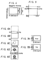
- the values which correspond to the PDI code are those of the normalized coordinates. These values are then shown on a video screen 1 of the CRT display 34, as best illustrated in Figure 5.
- the resolution of the display is determined by the resolution capability or normalization of a user's terminal apparatus. For example, even if the graphical figure is transmitted for a resolution of 4096 dots per line, which is the highest resolution available, a user's terminal apparatus must be of the same capability as that of the transmitter in order to display such a high resolution picture. If the user's terminal apparatus is capable of displaying only 256 dots, a low resolution picture is displayed by only displaying a fraction of the 4096 dots, e.g., only every 16th dot for a standard TV display. If the user's terminal apparatus, however, has a high resolution capability, the entire 4096 dots can be displayed.
- EP-A-0068619 discloses a display terminal in which character instructions are translated into picture description bit patterns which are stored in a graphic repertory for subsequent retrieval under control of code received from the source. Hence, relatively simple instructions as regards size, position, orientation of the particular required stored bit patterns may be used to form the desired image.
- the display data will cause the graphical picture displayed on the CRT display to be compressed or expanded in the vertical direction, depending on the type of system used.
- the present invention provides an image accessing terminal comprising visual display means, a buffer memory for storing received visual display data in a normalised coordinate form, a display memory for storing visual data in an absolute coordinate form, and control processor means connected to the visual display means, the buffer memory, and the display memory characterised in that the buffer memory stores a frame of visual display data in a form independent of the type of the visual display means and the arrangement is such that, in use, visual data read out from the buffer memory is converted to a frame of data in absolute coordinate form and written into the display memory, the absolute coordinate form being selectable from one of at least two preselected standards corresponding to at least two different types of visual display means, the converted visual display data being scaled to correspond to the resolution and aspect ratio of the visual display means, and the stored visual display data is read out from the display memory to cause the visual display means to display a corresponding image.
- the present invention therefore allows a terminal apparatus which may be, for example, a NAPLPS system, to use a CRT display of either the NTSC system of the PAL system by carrying out a predetermined decoding for the PDI code and a predermined mapping for the display system.
- the pixel data is thereafter read out from the display memory and displayed, it will have the correct position and aspect ratio for either the NTSC or PAL display screen. If the display screen is less than full resolution, this is compensated for by only storing a corresponding fraction of the pixel data in the display memory.
- this operation is carried out by a programmed central processing unit which is operatively connected to the buffer memory for storing received visual (i.e. pixel) information data in a normalised coordinate form, a display memory for storing visual information data in an absolute coordinate form and a visual display means for displaying the pixel data read out of the display memory.
- a programmed central processing unit which is operatively connected to the buffer memory for storing received visual (i.e. pixel) information data in a normalised coordinate form, a display memory for storing visual information data in an absolute coordinate form and a visual display means for displaying the pixel data read out of the display memory.
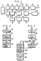
- System 9 comprises a programmed, central processing unit (CPU) 11, a read-only memory (ROM) 12 and random-access memories (RAM's) 13-16.
- Memories 12-16 are connected to CPU 11 via a system bus 19.
- CPU 11 in the preferred embodiment is a 16-bit processing device.
- ROM 12 contains various written programs such as a program for CPU 11 to decode the PDI code that is transmitted to a conventional display.
- ROM 12 also stores other programs such as routines 50 and 60, which are illustrated as flow diagrams in Figures 2 and 3.
- RAM 13 is the memory for a work area of CPU 11;
- RAM 14 is a page memory that can store the PDI codes of several pages;
- RAM 15 is a buffer memory that is capable of accessing the PDI code in RAM 14, the display memory, etc.
- RAM 16 a C-MOS type memory in the preferred embodiment, is capable of storing data indicative of a mode of the user's terminal apparatus and other data when the power of the user's terminal apparatus has been turned off.
- system 9 comprises a modem 31 that is connected via an interface (I/F) 21 to system bus 19. Modem 31 is also connected via a telephone network line 41 to a videotex center or host computer, not shown. Further, a full keyboard (FKB) 32 is provided. Keyboard 32 is connected via an interface (I/F) 22 to system bus 19 such that input data from keyboard 32 is forwarded to CPU 11.
- System 9 also includes a floppy disk drive (FDD) 33. Floppy disk drive 33 is connected via a floppy disk controller (FDC) 23 to system bus 19, through which data are forwarded to a floppy disk, not shown.
- FDD floppy disk drive
- FDC floppy disk controller
- system 9 comprises a display memory 17.
- Display memory 17 in the preferred embodiment is a video RAM.
- Display memory 17 is connected via a cathode ray tube controller (CRTC) 24 to system bus 19.
- Controller 24 in turn is connected to a cathode ray tube (CRT) display 34.
- CRTC cathode ray tube controller
- the display data i.e., pixel data from CPU 11 is first written through controller 24 into a particular address of display memory 17.
- the particular address in display memory 17 is an address specified by CPU 11 and corresponds to a display position on the screen 1 of the display means 34.
- the pixel data are read out from display memory 17, with its addresses synchronized with the vertical and horizontal scannings of display 34. This read-out is controlled by controller 24.
- the read-out pixel data are supplied to display 34, and then displayed thereon as a graphical picture.
- controller 24 can be operated either in the NTSC mode or the PAL mode, with the particular operational mode determined by CPU 11.
- the total horizontal addresses stored in display memory 17 represent 256 dots and for the vertical addresses, 240 dots. If display 34 utilizes the NTSC system, only the first 200 dots of the vertical address are used. If the PAL system is used, all 240 dots of the vertical addresses are used. It should be understood that if the display 34 has a higher resolution capability, the memory 17 would preferably have correspondingly more addresses.
- program routine 50 is executed by the CPU 11, as best shown in Figure 2.
- routine 50 begins with step 51.
- data indicative of the display mode, stored in RAM 16 is read out from RAM 16. These data indicate whether the display device was in the NTSC mode or the PAL mode when the user's terminal apparatus was last used.
- step 53 based on the determined result of step 52, data are supplied to controller 24, setting controller 24 to the mode that was used last. Accordingly, the user's terminal apparatus is now set to the previously used mode.
- This display mode can be changed by a key input from keyboard 32, and if the display mode is changed, data indicative of a new display mode are stored in RAM 16. Then, at step 54, the program routine goes to a main routine that is used for the user's terminal apparatus.
- program routine 60 When the display data decoded from the PDI code are written into display memory 17, program routine 60 is executed by CPU 11, as best shown in Figure 3.
- Program routine 60 begins with step 61 and the display mode data are read out from RAM 16 at step 62.
- the above data are used to determine whether the display mode is either the NTSC mode or the PAL mode. If it is in the NTSC mode, the program routine goes to step 64. If it is in the PAL mode, the program routine goes to step 65.
- the normalized, decoded data indicative of the display coordinate are converted to an absolute coordinate in the NTSC mode.
- the resolution as actually presented on the display 34 is 200 dots in the vertical direction and 256 dots in the horizontal direction when the system is in the NTSC mode, it is deemed for the purposes to be described as though it has 3200 dots in the vertical direction and 4096 dots in the horizontal direction to be compatible with the highest resolution requirements of the transmitted code.
- the coordinates are then converted from the normalized values to the absolute value. For instance, a vertical coordinate "0.5" (normalized value) is converted to "1600" (absolute value of 0.5 x 3200). Similarly, the coordinate of the dot in Figure 6C would be (1230, 1200) (rounded off).
- step 65 data indicative of the coordinates are converted to the absolute coordinate of the PAL mode. More specifically, although the resolution in the PAL mode is presented as 240 dots in the vertical direction and 256 dots in the horizontal direction, it is deemed to have 3840 dots in the vertical direction and 4096 dots in the horizontal direction for its highest resolution.
- the coordinates are then converted from the normalized values to the absolute values. For example, "0.5" in the vertical coordinate is converted to "1920" and the dot in Figure 6C has the absolute value coordinates of (1230, 1440).
- step 64 the program routine goes to step 66.
- step 66 the absolute coordinates that were converted at step 64 or 65 are written to corresponding addresses of display memory 17.
- the writing operation stores all the pixel data for the absolute value coordinates at the corresponding addresses in the display memory 17. If the display memory has less than full resolution, e.g., 1/16th of the full resolution in the case of a TV display, then only every 16th pixel data so converted is actually stored in the display memory 17.
- Program routine 60 ends with step 68.
- CRT display 34 may be of either the NTSC system or the PAL system, the graphical figure is displayed with the correct aspect ratio.
- the addresses of the image data are transmitted from the center in the form of normalized coordinate values.
- These normalized coordinate values are converted into either absolute coordinate values of PAL or NTSC depending on the commands.
- the absolute value or coordinate means the maximum value for the display.
- the display has 4096 x 4096 dots, such as a plasma flat display having an aspect ratio of 1:1
- the normalized value is converted on the basis of 4096 x 4096 displayable data dots.
- the number of horizontal scan lines should be also considered. For example, a raster scan display generally used in an expensive computer graphics system has more horizontal scan lines than a TV display.
- the normalized value of the address is converted on the basis of 1024 x 1000 displayable dots.
- a TV display is used as the display device.
- a TV display has a display faculty of 256 x 200 dots for NTSC and 240 x 256 dots for PAL.
- the data are transferred by simple thinning out processing. Namely, only every 16th data are transferred to the memory 17 relating to X address and Y address. This is done under the control of the CPU 11.
- the data indicative of the coordinate are converted from the normalized value to the absolute value of either the NTSC system or PAL system. Since the address of display memory 17 contains coordinate data in an absolute value format, the display data may be displayed in display 34 regardless of its mode. Whether display 34 is in the NTSC system or the PAL system, the graphical figure displayed has the correct aspect ratio. Further, when the coordinate is converted, the conversion is carried out such that the resolution is regarded as the highest one, so that even when the resolution of the display is increased by increasing the capacity of display memory 17, the algorithm of routine 60 need not be changed.
Landscapes
- Engineering & Computer Science (AREA)
- Physics & Mathematics (AREA)
- Computer Hardware Design (AREA)
- General Physics & Mathematics (AREA)
- Theoretical Computer Science (AREA)
- Television Systems (AREA)
- Controls And Circuits For Display Device (AREA)
- Two-Way Televisions, Distribution Of Moving Picture Or The Like (AREA)
- Financial Or Insurance-Related Operations Such As Payment And Settlement (AREA)
- Studio Devices (AREA)
Claims (6)
- Bildzugangsgerät mit einer Sichtanzeigeeinrichtung (34), einem Pufferspeicher (15) zur Speicherung von Sichtanzeigedaten in einer normierten Koordinatenform, einem Anzeigespeicher (17) zur Speicherung von Sichtdaten in einer absoluten Koordinatenform und einer mit der Sichtanzeigeeinrichtung (34), dem Pufferspeicher (15) und dem Anzeigespeicher (17) verbundenen Steuerprozessoreinrichtung (11),
dadurch gekennzeichnet,
daß der Pufferspeicher einen Rahmen von Sichtanzeigedaten in einer vom Typ der Sichtanzeigeeinrichtung unabhängigen Form speichert und daß die Anordnung derart ist, daß im Gebrauch von dem Pufferspeicher ausgelesene Sichtdaten in einen Datenrahmen in absoluter Koordinatenform umgewandelt und in den Anzeigespeicher (17) eingeschrieben werden, daß die absolute Koordinatenform aus einem von mindestens zwei vorgewählten Standards wählbar ist, welche mindestens zwei verschiedenen Typen von Sichtanzeigeeinrichtungen entsprechen, daß die umgewandelten Sichtanzeigedaten maßstabsgerecht geändert werden, um der Auflösung und dem Bildformat der Sichtanzeigeeinrichtung (34) zu entsprechen, und daß die gespeicherten Sichtanzeigedaten aus dem Anzeigespeicher (17) ausgelesen werden, um die Sichtanzeigeeinrichtung (34) zur Anzeige eines entsprechenden Bildes zu veranlassen. - Gerät nach Anspruch 1, in dem das Auslesen von Daten aus dem Pufferspeicher (15), ihre Umwandlung und das Schreiben der umgewandelten Daten durch die Steuerprozessoreinrichtung (11) ausgeführt werden.
- Gerät nach Anspruch 1 oder 2, dadurch gekennzeichnet, daß die zwei vorgewählten Standards NTSC und PAL sind.
- Gerät nach Anspruch 1 oder 2, dadurch gekennzeichnet, daß die Steuerprozessoreinrichtung (11) die horizontalen Koordinatendaten durch Multiplizieren des Wertes der normierten Koordinate mit 4096 umwandelt, um die absolute horizontale Koordinate zu erhalten, und dann die Sichtanzeigedaten für diese absolute horizontale Koordinate unter einer entsprechenden Adresse in der Anzeigespeichereinrichtung (17) speichert.
- Gerät nach Anspruch 4, dadurch gekennzeichnet, daß die Steuerprozessoreinrichtung (11) beim Betrieb in einem NTSC-Programmodus die vertikalen Koordinatendaten durch Multiplizieren des Wertes der normierten Koordinatendaten mit 3200 umwandelt, um die absolute vertikale Koordinate zu erhalten, und dann die Sichtanzeigedaten für diese absolute vertikale Koordinate unter einer entsprechenden Adresse in der Anzeigespeichereinrichtung (17) speichert.
- Gerät nach Anspruch 4 oder 5, dadurch gekennzeichnet, daß die Steuerprozessoreinrichtung (11) beim Betrieb in dem PAL-Modus die vertikalen Koordinatendaten durch Multiplizieren des Wertes der normierten Koordinatendaten mit 3840 umwandelt, um die absolute vertikale Koordinate zu erhalten, und dann die Sichdaten für diese absolute vertikale Koordinate unter einer entsprechenden Adresse in der Anzeigespeichereinrichtung (17) speichert.
Priority Applications (1)
| Application Number | Priority Date | Filing Date | Title |
|---|---|---|---|
| AT86301840T ATE89425T1 (de) | 1985-03-18 | 1986-03-13 | Endgeraet fuer ein bildschirmtextsystem. |
Applications Claiming Priority (2)
| Application Number | Priority Date | Filing Date | Title |
|---|---|---|---|
| JP53876/85 | 1985-03-18 | ||
| JP60053876A JPH088681B2 (ja) | 1985-03-18 | 1985-03-18 | ビデオテックスの端末装置 |
Publications (3)
| Publication Number | Publication Date |
|---|---|
| EP0195608A2 EP0195608A2 (de) | 1986-09-24 |
| EP0195608A3 EP0195608A3 (en) | 1988-10-12 |
| EP0195608B1 true EP0195608B1 (de) | 1993-05-12 |
Family
ID=12954946
Family Applications (1)
| Application Number | Title | Priority Date | Filing Date |
|---|---|---|---|
| EP86301840A Expired - Lifetime EP0195608B1 (de) | 1985-03-18 | 1986-03-13 | Endgerät für ein Bildschirmtextsystem |
Country Status (6)
| Country | Link |
|---|---|
| US (1) | US5117484A (de) |
| EP (1) | EP0195608B1 (de) |
| JP (1) | JPH088681B2 (de) |
| AT (1) | ATE89425T1 (de) |
| CA (1) | CA1304496C (de) |
| DE (1) | DE3688406T2 (de) |
Families Citing this family (7)
| Publication number | Priority date | Publication date | Assignee | Title |
|---|---|---|---|---|
| DE68927820T2 (de) * | 1988-12-06 | 1997-07-10 | Canon Kk | Bildaufnahmesystem |
| DE69225158T2 (de) * | 1991-02-01 | 1998-08-27 | Canon Kk | Bildverarbeitungsgerät |
| CN1049992C (zh) * | 1994-09-16 | 2000-03-01 | 联华电子股份有限公司 | 用于图像合成装置的位置转换装置 |
| US6515678B1 (en) * | 1999-11-18 | 2003-02-04 | Gateway, Inc. | Video magnifier for a display of data |
| JP4928676B2 (ja) * | 2000-09-04 | 2012-05-09 | 株式会社リコー | ビデオ信号出力装置、ビデオ信号出力方法およびその方法をコンピュータに実行させるプログラムを記録したコンピュータ読み取り可能な記録媒体 |
| US9381427B2 (en) | 2012-06-01 | 2016-07-05 | Microsoft Technology Licensing, Llc | Generic companion-messaging between media platforms |
| US9798457B2 (en) | 2012-06-01 | 2017-10-24 | Microsoft Technology Licensing, Llc | Synchronization of media interactions using context |
Citations (1)
| Publication number | Priority date | Publication date | Assignee | Title |
|---|---|---|---|---|
| EP0068619A1 (de) * | 1981-05-19 | 1983-01-05 | Western Electric Company, Incorporated | Generierung im Terminal von dynamisch redefinierbaren Zeichenvorräten |
Family Cites Families (9)
| Publication number | Priority date | Publication date | Assignee | Title |
|---|---|---|---|---|
| US4303986A (en) * | 1979-01-09 | 1981-12-01 | Hakan Lans | Data processing system and apparatus for color graphics display |
| GB2070399B (en) * | 1980-02-27 | 1983-10-05 | Xtrak Corp | Real time toroidal pan |
| US4462024A (en) * | 1981-03-24 | 1984-07-24 | Rca Corporation | Memory scanning address generator |
| JPS57158879A (en) * | 1981-03-27 | 1982-09-30 | Tokyo Shibaura Electric Co | Scanning converter |
| US4439759A (en) * | 1981-05-19 | 1984-03-27 | Bell Telephone Laboratories, Incorporated | Terminal independent color memory for a digital image display system |
| US4477802A (en) * | 1981-12-17 | 1984-10-16 | The Bendix Corporation | Address generator for generating addresses to read out data from a memory along angularly disposed parallel lines |
| US4533952A (en) * | 1982-10-22 | 1985-08-06 | Digital Services Corporation | Digital video special effects system |
| US4626837A (en) * | 1983-11-17 | 1986-12-02 | Wyse Technology | Display interface apparatus |
| DE3677561D1 (de) * | 1985-09-12 | 1991-03-28 | Sony Corp | Protokollumsetzer fuer ein videotextsystem. |
-
1985
- 1985-03-18 JP JP60053876A patent/JPH088681B2/ja not_active Expired - Fee Related
-
1986
- 1986-03-12 CA CA000503868A patent/CA1304496C/en not_active Expired - Lifetime
- 1986-03-13 DE DE86301840T patent/DE3688406T2/de not_active Expired - Fee Related
- 1986-03-13 AT AT86301840T patent/ATE89425T1/de not_active IP Right Cessation
- 1986-03-13 EP EP86301840A patent/EP0195608B1/de not_active Expired - Lifetime
-
1989
- 1989-02-03 US US07/305,616 patent/US5117484A/en not_active Expired - Lifetime
Patent Citations (1)
| Publication number | Priority date | Publication date | Assignee | Title |
|---|---|---|---|---|
| EP0068619A1 (de) * | 1981-05-19 | 1983-01-05 | Western Electric Company, Incorporated | Generierung im Terminal von dynamisch redefinierbaren Zeichenvorräten |
Also Published As
| Publication number | Publication date |
|---|---|
| DE3688406D1 (de) | 1993-06-17 |
| US5117484A (en) | 1992-05-26 |
| ATE89425T1 (de) | 1993-05-15 |
| CA1304496C (en) | 1992-06-30 |
| EP0195608A2 (de) | 1986-09-24 |
| JPH088681B2 (ja) | 1996-01-29 |
| JPS61212977A (ja) | 1986-09-20 |
| EP0195608A3 (en) | 1988-10-12 |
| DE3688406T2 (de) | 1993-10-21 |
Similar Documents
| Publication | Publication Date | Title |
|---|---|---|
| CA1181880A (en) | Terminal generation of dynamically redefinable character sets | |
| CA1191636A (en) | Pictorial information processing technique | |
| CN1103159C (zh) | 使用双画面型屏幕的信息与外部信号显示设备 | |
| US4377852A (en) | Terminal emulator | |
| US8199136B2 (en) | Image data transmission apparatus and method for image display system | |
| EP0260883A2 (de) | Bilddrehungsverfahren | |
| JPH0569438B2 (de) | ||
| GB2099267A (en) | Method and system for providing a video display | |
| US6388679B1 (en) | Multi-resolution computer display system | |
| EP0195608B1 (de) | Endgerät für ein Bildschirmtextsystem | |
| US9013633B2 (en) | Displaying data on lower resolution displays | |
| US7164431B1 (en) | System and method for mixing graphics and text in an on-screen display application | |
| JP2001509920A (ja) | 補間用のラインバッファを画素のルックアップテーブルとして用いる方法及び装置 | |
| EP1271409B1 (de) | Verfahren und System zur Erzeugung eines digitalen Bildes, das ein transparentes Objekt umfasst | |
| EP0196191A2 (de) | Verfahren und Vorrichtung zur Umsetzung eines Prestel-Kodes in einen NAPLPS-Kode | |
| JP3297344B2 (ja) | グラフィックス表示アダプタ | |
| US7109996B1 (en) | Apparatus and method for rendering characters into a memory | |
| JPS5823086A (ja) | 表示装置 | |
| AU8584182A (en) | Terminal generation of dynamically redefinable character sets | |
| JPH08106536A (ja) | 画像の抽出・圧縮方法、画像伝送装置、画像記録装置 | |
| JPH0763186B2 (ja) | ビデオテツクス信号変換回路 | |
| JPH08331288A (ja) | ファクシミリ文書のイメージ表示装置 | |
| JPH0721404A (ja) | ウィンドウデータの切り出し装置 | |
| HK1005387B (en) | Apparatus and method of windowing a vga image | |
| JPS60113290A (ja) | 表示装置 |
Legal Events
| Date | Code | Title | Description |
|---|---|---|---|
| PUAI | Public reference made under article 153(3) epc to a published international application that has entered the european phase |
Free format text: ORIGINAL CODE: 0009012 |
|
| 17P | Request for examination filed |
Effective date: 19860317 |
|
| AK | Designated contracting states |
Kind code of ref document: A2 Designated state(s): AT DE FR GB NL |
|
| PUAL | Search report despatched |
Free format text: ORIGINAL CODE: 0009013 |
|
| AK | Designated contracting states |
Kind code of ref document: A3 Designated state(s): AT DE FR GB NL |
|
| 17Q | First examination report despatched |
Effective date: 19910121 |
|
| GRAA | (expected) grant |
Free format text: ORIGINAL CODE: 0009210 |
|
| AK | Designated contracting states |
Kind code of ref document: B1 Designated state(s): AT DE FR GB NL |
|
| REF | Corresponds to: |
Ref document number: 89425 Country of ref document: AT Date of ref document: 19930515 Kind code of ref document: T |
|
| REF | Corresponds to: |
Ref document number: 3688406 Country of ref document: DE Date of ref document: 19930617 |
|
| ET | Fr: translation filed | ||
| REG | Reference to a national code |
Ref country code: GB Ref legal event code: IF02 |
|
| PGFP | Annual fee paid to national office [announced via postgrant information from national office to epo] |
Ref country code: FR Payment date: 20020312 Year of fee payment: 17 |
|
| PGFP | Annual fee paid to national office [announced via postgrant information from national office to epo] |
Ref country code: GB Payment date: 20020313 Year of fee payment: 17 Ref country code: AT Payment date: 20020313 Year of fee payment: 17 |
|
| PGFP | Annual fee paid to national office [announced via postgrant information from national office to epo] |
Ref country code: DE Payment date: 20020327 Year of fee payment: 17 |
|
| PGFP | Annual fee paid to national office [announced via postgrant information from national office to epo] |
Ref country code: NL Payment date: 20020328 Year of fee payment: 17 |
|
| PG25 | Lapsed in a contracting state [announced via postgrant information from national office to epo] |
Ref country code: GB Free format text: LAPSE BECAUSE OF NON-PAYMENT OF DUE FEES Effective date: 20030313 Ref country code: AT Free format text: LAPSE BECAUSE OF NON-PAYMENT OF DUE FEES Effective date: 20030313 |
|
| PG25 | Lapsed in a contracting state [announced via postgrant information from national office to epo] |
Ref country code: NL Free format text: LAPSE BECAUSE OF NON-PAYMENT OF DUE FEES Effective date: 20031001 Ref country code: DE Free format text: LAPSE BECAUSE OF NON-PAYMENT OF DUE FEES Effective date: 20031001 |
|
| GBPC | Gb: european patent ceased through non-payment of renewal fee |
Effective date: 20030313 |
|
| PG25 | Lapsed in a contracting state [announced via postgrant information from national office to epo] |
Ref country code: FR Free format text: LAPSE BECAUSE OF NON-PAYMENT OF DUE FEES Effective date: 20031127 |
|
| NLV4 | Nl: lapsed or anulled due to non-payment of the annual fee |
Effective date: 20031001 |
|
| REG | Reference to a national code |
Ref country code: FR Ref legal event code: ST |
|
| PLBE | No opposition filed within time limit |
Free format text: ORIGINAL CODE: 0009261 |
|
| STAA | Information on the status of an ep patent application or granted ep patent |
Free format text: STATUS: NO OPPOSITION FILED WITHIN TIME LIMIT |