EP0195372B1 - Method and apparatus for forming 3x3 pixel arrays and for performing programmable pattern contingent modifications of those arrays - Google Patents
Method and apparatus for forming 3x3 pixel arrays and for performing programmable pattern contingent modifications of those arrays Download PDFInfo
- Publication number
- EP0195372B1 EP0195372B1 EP86103415A EP86103415A EP0195372B1 EP 0195372 B1 EP0195372 B1 EP 0195372B1 EP 86103415 A EP86103415 A EP 86103415A EP 86103415 A EP86103415 A EP 86103415A EP 0195372 B1 EP0195372 B1 EP 0195372B1
- Authority
- EP
- European Patent Office
- Prior art keywords
- window
- pixel
- raster
- bit
- pixels
- Prior art date
- Legal status (The legal status is an assumption and is not a legal conclusion. Google has not performed a legal analysis and makes no representation as to the accuracy of the status listed.)
- Expired
Links
- 238000003491 array Methods 0.000 title claims description 8
- 238000000034 method Methods 0.000 title description 11
- 238000012986 modification Methods 0.000 title description 3
- 230000004048 modification Effects 0.000 title description 3
- 238000004422 calculation algorithm Methods 0.000 claims description 6
- 238000006243 chemical reaction Methods 0.000 claims description 5
- 238000012937 correction Methods 0.000 claims description 5
- 230000004044 response Effects 0.000 claims description 3
- 230000008878 coupling Effects 0.000 claims 1
- 238000010168 coupling process Methods 0.000 claims 1
- 238000005859 coupling reaction Methods 0.000 claims 1
- 239000013598 vector Substances 0.000 description 9
- 238000012545 processing Methods 0.000 description 8
- 238000010586 diagram Methods 0.000 description 5
- 238000003384 imaging method Methods 0.000 description 5
- 230000008569 process Effects 0.000 description 5
- 230000006870 function Effects 0.000 description 4
- 238000012546 transfer Methods 0.000 description 4
- 238000009499 grossing Methods 0.000 description 3
- 230000003287 optical effect Effects 0.000 description 3
- 230000004075 alteration Effects 0.000 description 2
- 230000008901 benefit Effects 0.000 description 2
- 230000009467 reduction Effects 0.000 description 2
- 230000009466 transformation Effects 0.000 description 2
- 238000000844 transformation Methods 0.000 description 2
- 238000013459 approach Methods 0.000 description 1
- 230000000712 assembly Effects 0.000 description 1
- 238000000429 assembly Methods 0.000 description 1
- 238000011960 computer-aided design Methods 0.000 description 1
- 238000010276 construction Methods 0.000 description 1
- 238000013500 data storage Methods 0.000 description 1
- 238000001514 detection method Methods 0.000 description 1
- 230000008030 elimination Effects 0.000 description 1
- 238000003379 elimination reaction Methods 0.000 description 1
- 230000001788 irregular Effects 0.000 description 1
- 238000004519 manufacturing process Methods 0.000 description 1
- 239000011159 matrix material Substances 0.000 description 1
- 238000007781 pre-processing Methods 0.000 description 1
- 238000012163 sequencing technique Methods 0.000 description 1
- 230000007704 transition Effects 0.000 description 1
- 238000013519 translation Methods 0.000 description 1
Images


Classifications
-
- H—ELECTRICITY
- H04—ELECTRIC COMMUNICATION TECHNIQUE
- H04N—PICTORIAL COMMUNICATION, e.g. TELEVISION
- H04N1/00—Scanning, transmission or reproduction of documents or the like, e.g. facsimile transmission; Details thereof
- H04N1/41—Bandwidth or redundancy reduction
- H04N1/411—Bandwidth or redundancy reduction for the transmission or storage or reproduction of two-tone pictures, e.g. black and white pictures
-
- G—PHYSICS
- G06—COMPUTING; CALCULATING OR COUNTING
- G06T—IMAGE DATA PROCESSING OR GENERATION, IN GENERAL
- G06T5/00—Image enhancement or restoration
- G06T5/20—Image enhancement or restoration using local operators
Definitions
- This invention relates to a hardware system for compressing information taken from existing documents for entry into a data base. More particularly, the invention relates to a method and apparatus for the high speed processing of raster-scanned data to effectively reduce the data necessary to represent lines and characters of the original document prior to storage of a vectorized representation of the original document in the data base.
- One of the most efficient and compact machine-script data sets representative of a picture comprises vectors including data items representing spatial location of the vectors with respect to the original picture.
- techniques for converting a picture into such vectorial data fall into two categories, viz.: line-following and raster-to-vector conversion.
- Line-following schemes while generating vectorial data directly, require large and expensive assemblies that are best suited for high production environments. Line-following is said to be advantageous because the original picture is used as the image memory, instead of a bit-map copy of the picture in the computer memory.
- a "bit-map" is a signal set in machine script representing a tessellation of small picture elements or pixels of the original document.
- line-following imaging systems having devices that can be directed randomly in two dimensions to detect and follow picture features are either expensive or slow.
- An example of the former comprises a device utilizing a scanning laser beam which is directed by moving mirrors, and having acousto-optical devices for detecting features of the picture.
- An example of the latter is an electromechanical device such as a plotter having a light sensor instead of a pen.
- an operator manually guides a carriage along a line to be acquired; a photosensor detects when the carriage is directly over a line and enables the system to store X and Y coordinates of the carriage.
- raster-to-vector conversion systems In raster-to-vector conversion systems, the original picture or its microfilm is scanned, e.g., optically, and the information thereon resolved into a bit-map. The optical characteristics of each pixel are used to control detection circuits that generate positionally defined signals of the bit-map.
- An advantage of raster-to-vector conversion systems is that raster-scan imaging devices are inexpensive and prevalent; however, this kind of system has commonly required storage of the entire image as a bit-map in a data store accessible by a computer, the computer then executing a program for converting the bit-map to a vectorial data set.
- bit-map copy of a picture requires a large data store.
- a bit stream acquired from raster scanning an E-size drawing with a resolution of 0.1 millimeter comprises approximately 100 million bits of data.
- a "bit stream” means a sequence of electrical signals or pulses comprising a set of binary digits representing data in coded form wherein the significance of each bit is determined by its position in the sequence and its relation to other bits.
- Various data reduction algorithms based on information and coding theory have been utilized to achieve significant reduction in the storage requirement for scanned data.
- the form of representation of data as coded messages generally lacks information necessary for reconstituting regular line drawings.
- the present invention as set forth in the claim provides a system for forming sequential windows of a predetermined size from a raster-scanned pixel bit stream from a selected document. Each of the windows is then examined using a selected one of several known algorithms for grouping adjacent pixels into smaller arrays to modify the raster-scanned bit stream before it is stored in a data base.
- each raster includes n (positive integer) pixels and the system operates on a bank of m (positive integer) sequential windows with each window being k ( odd integer of 3 or more) wide and j (odd integer of 3 or more) high.
- the system includes a counter for selecting each of the m windows sequentially.
- a pattern memory is included to store selected predetermined correction factors for each possible pixel pattern in each of the m windows.
- a pattern selection memory is provided to address the pattern memory to make that selection.
- the bit values of the window being examined are applied to the balance of the address lines of the pattern memory.
- the appropriate correction factor is selected and stored in a single bit delay to be used as the first bit of the next window.
- a register file is provided for receiving the bit values of the first 0-1) pixels in each of the k rasters of the present window to be shifted to become the bit values for the last (j-1) pixels in the next window.
- bit value of each of the last pixels in the first (k-1) rasters of the present window are applied to an (n-1) raster delay storage and the output bits of that storage unit are provided to the pattern memory for the first pixel in the last (k-1) rasters of the next window. This sequence thus progresses similarly for subsequent windows.
- Fig. 1 shows a simplified block diagram of an automatic picture coding system 10.
- That picture coding system comprises an image acquisition element 12 which converts an image of a document 14 into electrical signals.
- a variety of means may be utilized to acquire an image of a document including scanners wherein the document to be read is moved past a fixed sensor and light source.
- An example is the facsimile drum scanner in which the original is attached to the outside of a rapidly rotating cylinder moving slowly along its axis with respect to the sensor, thus producing a raster-scanned image of the document.
- the original document and the detector remain fixed and the scanning is effected by moving mirrors.
- a second type of scanner is one in which a small intense spot of light is scanned over a document, light reflected from the document being detected by a single-element detector with no particular directional characteristics.
- Such scanners include laser scanners having moving mirrors which scan a laser spot across the picture.
- a moving spot may also be produced by focusing the face of a raster-scanned CRT onto the document.
- Another scanning approach involves scanning the document or an optical image of the document, with an area detector such as a vidicon or a solid-state imaging array.
- the image acquisition element 12 of system 10 utilizes a form of raster scanning to dissect an optical image of the document 14 into a plurality of columns of square picture elements or pixels, one of which columns 16 is depicted in Fig. 1.
- a linear array of photosensitive charge-coupled devices (CCD) could be used to sense one entire column 16 of contiguous pixels of the appropriately illuminated document 14.
- the light intensity in each pixel is compared with a threshold value and converted to a binary digital signal representing either a black or a white area of the document 14.
- the electrical signals representing the column -16 are coupled via a connection 18 to a digital hardware element 20.
- the entire document 14 is scanned by successively repositioning the linear CCD imaging array in the direction perpendicular to the column 16 by mechanical means 22 responsive to the digital hardware element 20.
- the result is a digital image in the form of a serial matrix or bit-map having elements representing the entire document 14.
- the digital hardware element 20 comprises a preprocessor 24 and a control logic element 26.
- the preprocessor 24 receives the serial digitized data from the image acquisition element 12 and performs a series of high-speed transformations on the data as it is received.
- the preprocessor 24 changes the data from a bit-map representation of the sensed image into a compact feature representation by performing selected preprocessing operations such as smoothing, growing, thinning, removing dots and voids, etc.
- Smoothing is a process which removes spurious points adjacent to a line, growing fills discontinuities in lines and broad features, thinning reduces broad features to skeletal lines usually no more than one pixel wide, and the process to remove dots and voids eliminates any representative dark or light areas that are smaller than the smallest information size designated by the user in the original drawing.
- the transformed data is transferred via a bus 28 to a microcomputer 30 for additional, high- level processing.
- the data output from the preprocessor 24 to the microcomputer 30 is still a bit-map representation of the document 14; however, only pixels associated with line data and edges are output to the microcomputer 30.
- the data is transferred in real time as the document 14 is being scanned.
- the microcomputer 30, under control of a software module 32, encodes and lists the data, and converts the listed data into an abstraction comprising a list of vectors representing the original document.
- a software module 32 encodes and lists the data, and converts the listed data into an abstraction comprising a list of vectors representing the original document.
- the control logic 26 serves as an interface between the microcomputer 30, the preprocessor 24, and the image acquisition element 12, providing control, sequencing and timing functions. Among these functions are control of the mechanical means 22 for scanning the imaging array as well as data transfer functions.
- the image acquisition element 12 comprises a lens 38, and an image detector 40.
- Document 14 is mounted on a rotating drum and one column of the document is focused onto the image detector 40 which, for illustrative purposes, is shown as a linear CCD photodiode array having N photosensitive elements receiving photons from the column 16. N is the maximum number of pixels around the circumference of the drum.
- the CCD photodiode array may scan a plurality of columns along the axis of the drum and store this data for the entire circumference of the drum.
- the lens 38 and image detector 40 are mounted on a carriage 42 which is connected to a stepper motor 44 by mechanical means 46.
- the charge is transferred from the photodiodes to a CCD analog shift register 48. After the transfer, the photodiodes 40 once again begin integrating light while the sensed charge pattern is shifted through the CCD analog shift register 48 to a threshold comparator 50.
- Each of the output voltages of the charge-pattern sequence representing the light striking each of the photodiodes in sequence along the array 40 is compared to a predetermined threshold voltage in the threshold comparator 50 and regenerated as a binary signal representative of the light/dark pattern of the sensed line wherein a binary "one" represents a black or dark area and "zero" represents a white or light area.
- a column or line of data sensed by the CCD array 40 is referred to herein as a "raster" of data, or simply, a raster.
- the image data from the CCD photodiode array is stored in a line store 52.
- New data is acquired by the image detector 40 while the previous image is being shifted out of the CCD shift register 48 into the line store 52.
- the stepper motor 44 is activated to begin moving the carriage 42 immediately after the transfer of data from the photodiode array 40 into the CCD shift register 48.
- the image detector 40 is moved on the carriage 42 which in the presently described embodiment is a micrometer driven translation stage, the micrometer 46 being turned by the stepper motor 44.
- the use of a stepper motor allows precise positioning of the array over a number of steps and allows the array 40 to be stepped intermittently precluding problems due to mechanical inertia.
- the stepper motor 44 is driven by a motor latch and drive circuit 54 in response to input signals from the system software.
- a raster of data stored in the line store 52 is transferred one bit at a time on demand to the preprocessor or window processor 24 under control of the control logic 26, and while this transfer is occurring, another raster of data is being acquired by the image acquisition element 12.
- the window processor 24 thus processes successive rasters of data as they are acquired utilizing a technique known in the art as "neighborhood” or window logic.
- Neighborhood logic refers to an operation performed digitally on an array of data A(I,J) which is carried out so as to transform A(I,J) into a new data array A'(I,J) wherein each element in the new array has a value determined only by the corresponding element in the original array along with the values of its nearest neighbors.
- the nearest neighbor configuration is called a "window" and apparatus performing operations on arrays of identically configured windows is called window logic.
- FIG. 3 there is shown a bit-map 60 of black and white pixels of sampled data representing a portion of a scanned document with successive raster portions being arranged vertically in the figure.
- a 3-pixel wide by 3-pixel high section of the bit-map 60 is defined as a window 62.
- a window such as the window 62 may be centered at any pixel in the image.
- a window such as the window 62 of the presently described embodiment of the invention is a square tessellation, other tessellations may be utilized.
- the window preprocessor 24 examines each of the 3x3 windows in the image serially a number of times and, based on the pattern of light and dark pixels within the window, changes a center pixel 64 from light to dark, from dark to light, or leaves it unchanged. This operation, applied sequentially to windows centered at each pixel in the image and, in some instances, repeated a number of times, performs all image transformations involved in thinning, growing, noise elimination and smoothing of the image.
- Fig. 4 represents a window of pixel data having 9 pixels labeled 8-0 as shown.
- the instant invention utilizes a data format wherein each window is expressed as a 9-bit binary word, each of the bits of the word having a numbered location in the window which corresponds with the binary weight of the bit, i.e., the most significant bit of the binary word corresponds with the center pixel (28); the least significant bit, with the pixel to the right of the center pixel (20) in Fig. 4.
- the window 62 of Fig. 3 is thus expressed as a binary number 100,001,111, or 417 8 in octal notation.
- a window 65 of Fig. 3 is expressed as 110,001,101 2 or 615s in the data format of the instant invention.
- Each window pattern thus has a unique number associated with it which represents one of 512 (29) possible patterns.
- This unique number is used in the window processor as a table- lock-up instruction to determine a value to use in the next window.
- the window 400 8 represents a single isolated black pixel in a field of white and may be considered as noise. The noise can be removed by loading a zero into the table location corresponding to the window 400 8 . The window processor would then output a zero to the next window for every occurrence of 400s.
- a window 377s having a white pixel in a field of black can be filled in by generating a "1" for the next window.
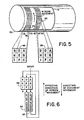
- a document 72 is shown mounted on a rotating drum 70 with a portion of the effective rasterization of the document superimposed thereon.
- individual vertically oriented rasters 74-84 each divided into a number of squares to represent the individual pixels.
- two data windows 86 and 88 are also shown.
- the window of data used during the processing may be different from an "actual" window of data in the document due to the processing algorithms being used.
- pixels A-C, D-F and G-I correspond to three of the pixels in each of rasters 78, 76 and 74, respectively, with pixel A being the most recently acquired, and pixel I being the earliest acquired by detector 40 or from the previous window.
- bit stream from the line store 52 is input to the window processor 24 via a bus 66. All nine bits of a window are examined simultaneously utilizing a tapped delay-line structure comprising 1-bit delay elements for each of the nine bit positions of window 90 and two (n-3)-bit delay elements 92 and 94, where n is equal to the integer number of pixels in a single raster scan of the document being digitized and entered into the data base.
- each bit represents a new bit "A"
- the previous bits then ripple through the corresponding storage units "B” and “C”
- raster delay 92 into the next raster positions of "D", “E” and “F”
- raster delay 94 then finally into the third raster positions of "G", "H” and “I”.
- the value from the table look-up instruction for one window then progresses to position "A” of the next window, or to microcomputer 30 if the function of preprocessor 24 is complete.
- window 90 has an effective direction of movement in the upward vertical direction and the document being scanned is moving in a downward vertical direction.
- Fig. 7 there is shown a detailed block diagram of a particular embodiment of the present invention.
- the embodiment of Fig. 7 is a cascading of eight of the 3x3 window arrays shown in Fig. 6.
- the circuit of Fig. 7 embodies a scheme for constructing eight non-recursive, 3x3 pixel arrays, or windows, on which a pattern "look-up" is performed on each window.
- the patterns and pattern selections for the algorithm of interest are loaded into pattern memory (RAM) 110 and pattern selection memory (RAM) 106 from microcomputer 30 and the bit values for pixels B-I of the first window are reset to zero.
- RAM pattern memory
- RAM pattern selection memory
- a pattern is a cluster of 512 bits with each bit representing either a written or unwritten pixel in an arrangement that determines an improved output by representing a vector segment (i.e., connectivity) by the minimum number of pixels based on each of the possible 512 input windows.
- a pixel with a bit value of 1 will be considered to be written, whereas a pixel with a bit value of 0 will be considered to be unwritten.
- the addition of pattern selection allows for the selection of a different pattern for each of the cascaded windows to be stored in pattern memory 110 independent of the order in which they will be used with microcomputer 30 controlling their ordering via pattern selection memory 106, the output signal of which provides additional address information to pattern memory 110.
- the balance of the address information for pattern memory 110 is provided by the bit information of the nine pixels (A-I) which make up the window being observed.
- This bank of eight windows receives the pixel data serially from image acquisition 12 (Fig. 1) or another bank via new pixel input line 134.
- the new pixel is then applied to the first window in the bank as pixel A and will only be seen by that window since pixel A of each of the subsequent windows is determined by the output state of pattern memory 110 as discussed below.
- the output signal of 3-bit counter 108 determines which window is being observed and the sequence of the windows (000 for the first window and 111 for the eighth window).
- pixels B, C, E, F, H, and I are read from register file 104, pixel A from multiplexer (Mux) 100 and pixels D and G from Muxs 128 and 132, respectively, to construct the first window of the bank for the balance of the address signals to pattern memory 110.
- Mux multiplexer
- the bit values " of each of the pixels in the 3x3 window together determine whether the center, or E pixel, bit value is a 1 or a 0 for subsequent processing of the raster-scanned bit stream.
- the new bit value of the center pixel in the first window resulting from the look-up operation of pattern memory 110 and output therefrom is stored in flip-flop 102 to be used as the bit value for pixel A in the second of the eight windows in the bank.
- the current bit values of pixels A, B, D, E, G, and H are rewritten into register file 104, and the current bit values of pixels C and F are written into 8-bit shift registers 112 and 114, respectively, and thereafter into the two 8-bit holding registers 116 and 118, respectively.
- Counter 108 is then incremented to create the second window.
- the bit value for pixel A is the output state of flip-flop 102 since Mux 100 only selects a new pixel when the count from counter 108 is 000.
- the bit values for pixels B, C, E, F, H, and I are obtained from register file 104 and those bit values correspond to the bit values of pixels A, B, D, E, G, and H, respectively, of the previous time that window was accessed.
- the bit value of pixels D and G is obtained from Muxs 128 and 132, respectively under the control of counter 108.
- the output state from pattern memory 110 thus provides the bit value for pixel A in the next window as discussed above.
- bit value of 16 pixels (pixels D and G of each window) must be recalled from raster delay storage 144 (where the (n-3) bit values of the pixels in each raster-scan which are not currently in a window are stored), the bit values of 16 other pixels (pixels C and F of each window) must be transferred from holding registers 116 and 118 to raster delay storage 144, and the modulo (n-3) counter 124 must be incremented to cause the bit values to ripple through (n-3) pixel storage registers 120 and 122 all of the raster delay storage 144.
- Pattern memory 110 in this embodiment is a 4Kxl RAM to accommodate the 8 times 512 data locations necessary for the eight windows of the bank.
- the pattern selection memory 106 is an 8x3 RAM to allow the random storage of the eight patterns in the pattern memory 110.
Landscapes
- Engineering & Computer Science (AREA)
- Multimedia (AREA)
- Signal Processing (AREA)
- Physics & Mathematics (AREA)
- General Physics & Mathematics (AREA)
- Theoretical Computer Science (AREA)
- Image Processing (AREA)
Description
- This invention relates to a hardware system for compressing information taken from existing documents for entry into a data base. More particularly, the invention relates to a method and apparatus for the high speed processing of raster-scanned data to effectively reduce the data necessary to represent lines and characters of the original document prior to storage of a vectorized representation of the original document in the data base.
- Computer-aided design and drafting is practised extensively in the engineering and graphic arts; however, there exists an extensive archive of documents generated manually or otherwise in pictorial form, i.e., more suitable for human interpretation than interpretation by machine. The demand for conversion of such archives to machine script will grow as the transition to computer-based graphics progresses and becomes more complete.
- Techniques for automatically converting drawings and other pictures to machine script for processing, storage or display are well known. One of the most efficient and compact machine-script data sets representative of a picture comprises vectors including data items representing spatial location of the vectors with respect to the original picture. Generally, techniques for converting a picture into such vectorial data fall into two categories, viz.: line-following and raster-to-vector conversion. Line-following schemes, while generating vectorial data directly, require large and expensive assemblies that are best suited for high production environments. Line-following is said to be advantageous because the original picture is used as the image memory, instead of a bit-map copy of the picture in the computer memory. A "bit-map" is a signal set in machine script representing a tessellation of small picture elements or pixels of the original document. Generally, line-following imaging systems having devices that can be directed randomly in two dimensions to detect and follow picture features are either expensive or slow. An example of the former comprises a device utilizing a scanning laser beam which is directed by moving mirrors, and having acousto-optical devices for detecting features of the picture. An example of the latter is an electromechanical device such as a plotter having a light sensor instead of a pen. In some implementations, an operator manually guides a carriage along a line to be acquired; a photosensor detects when the carriage is directly over a line and enables the system to store X and Y coordinates of the carriage. By moving the carriage on an irregular path over the line, the intersections of the path and the line are stored as end points of a string of vectors. A totally automatic line-following system must first scan the entire picture to locate lines and features, and maintain a data-storage bookkeeping system to preclude duplicate storage of data. Otherwise, an operator must locate lines and direct the process, line by line.
- In raster-to-vector conversion systems, the original picture or its microfilm is scanned, e.g., optically, and the information thereon resolved into a bit-map. The optical characteristics of each pixel are used to control detection circuits that generate positionally defined signals of the bit-map. An advantage of raster-to-vector conversion systems is that raster-scan imaging devices are inexpensive and prevalent; however, this kind of system has commonly required storage of the entire image as a bit-map in a data store accessible by a computer, the computer then executing a program for converting the bit-map to a vectorial data set.
- The storage of a bit-map copy of a picture requires a large data store. For example, a bit stream acquired from raster scanning an E-size drawing with a resolution of 0.1 millimeter comprises approximately 100 million bits of data. A "bit stream" means a sequence of electrical signals or pulses comprising a set of binary digits representing data in coded form wherein the significance of each bit is determined by its position in the sequence and its relation to other bits. Various data reduction algorithms based on information and coding theory have been utilized to achieve significant reduction in the storage requirement for scanned data. Unfortunately, however, the form of representation of data as coded messages generally lacks information necessary for reconstituting regular line drawings.
- Previously, software has been used to process digitized drawings before vectorization by grouping adjacent pixels into small arrays, and altering some of the pixels depending on the configuration. This required a lot of time and system resources.
- It would be desirable to have a compact, high speed, lower cost hardware system with the capability of varying the raster lengths for various sized drawings while incorporating the benefits of the software approach programmable patterns through the utilization of readily available and inexpensive components such as TTL and CMOS devices.
- In accordance with the illustrated embodiment, the present invention as set forth in the claim provides a system for forming sequential windows of a predetermined size from a raster-scanned pixel bit stream from a selected document. Each of the windows is then examined using a selected one of several known algorithms for grouping adjacent pixels into smaller arrays to modify the raster-scanned bit stream before it is stored in a data base. In the most general case, each raster includes n (positive integer) pixels and the system operates on a bank of m (positive integer) sequential windows with each window being k ( odd integer of 3 or more) wide and j (odd integer of 3 or more) high.
- The system includes a counter for selecting each of the m windows sequentially. A pattern memory is included to store selected predetermined correction factors for each possible pixel pattern in each of the m windows. To select the appropriate pattern for the window being examined, a pattern selection memory is provided to address the pattern memory to make that selection. In addition, the bit values of the window being examined are applied to the balance of the address lines of the pattern memory. In response thereto the appropriate correction factor is selected and stored in a single bit delay to be used as the first bit of the next window. In addition, a register file is provided for receiving the bit values of the first 0-1) pixels in each of the k rasters of the present window to be shifted to become the bit values for the last (j-1) pixels in the next window. Also, the bit value of each of the last pixels in the first (k-1) rasters of the present window are applied to an (n-1) raster delay storage and the output bits of that storage unit are provided to the pattern memory for the first pixel in the last (k-1) rasters of the next window. This sequence thus progresses similarly for subsequent windows.
- A full understanding of the present invention will be obtained from a detailed description given hereinbelow and the accompanying drawings. In addition, the drawings are given by way of illustration only, and thus are not limitative of the present invention. Further, wherein:
- Fig. 1 is a block diagram of an automatic picture coding system in accordance with the instant invention.
- Fig. 2 is a more detailed block diagram of the system of Fig. 1.
- Figs. 3 and 4 illustrate a data format utilized in the practice of the present invention.
- Fig. 5 illustrates the mounting of the document to be stored electronically on a drum including a representation of the rasters, pixels and windows used by the present invention.
- Fig. 6 shows a simplified representation of a single window generation technique of the present invention.
- Fig. 7 shows a detailed block diagram of the present invention.
- Fig. 1 shows a simplified block diagram of an automatic
picture coding system 10. That picture coding system comprises an image acquisition element 12 which converts an image of adocument 14 into electrical signals. A variety of means may be utilized to acquire an image of a document including scanners wherein the document to be read is moved past a fixed sensor and light source. An example is the facsimile drum scanner in which the original is attached to the outside of a rapidly rotating cylinder moving slowly along its axis with respect to the sensor, thus producing a raster-scanned image of the document. In a variation of the foregoing, the original document and the detector remain fixed and the scanning is effected by moving mirrors. A second type of scanner is one in which a small intense spot of light is scanned over a document, light reflected from the document being detected by a single-element detector with no particular directional characteristics. Such scanners include laser scanners having moving mirrors which scan a laser spot across the picture. A moving spot may also be produced by focusing the face of a raster-scanned CRT onto the document. Another scanning approach involves scanning the document or an optical image of the document, with an area detector such as a vidicon or a solid-state imaging array. - The image acquisition element 12 of
system 10 utilizes a form of raster scanning to dissect an optical image of thedocument 14 into a plurality of columns of square picture elements or pixels, one of whichcolumns 16 is depicted in Fig. 1. A linear array of photosensitive charge-coupled devices (CCD) could be used to sense oneentire column 16 of contiguous pixels of the appropriately illuminateddocument 14. The light intensity in each pixel is compared with a threshold value and converted to a binary digital signal representing either a black or a white area of thedocument 14. The electrical signals representing the column -16 are coupled via aconnection 18 to a digital hardware element 20. Theentire document 14 is scanned by successively repositioning the linear CCD imaging array in the direction perpendicular to thecolumn 16 bymechanical means 22 responsive to the digital hardware element 20. The result is a digital image in the form of a serial matrix or bit-map having elements representing theentire document 14. - The digital hardware element 20 comprises a
preprocessor 24 and acontrol logic element 26. Thepreprocessor 24 receives the serial digitized data from the image acquisition element 12 and performs a series of high-speed transformations on the data as it is received. Thepreprocessor 24 changes the data from a bit-map representation of the sensed image into a compact feature representation by performing selected preprocessing operations such as smoothing, growing, thinning, removing dots and voids, etc. Smoothing is a process which removes spurious points adjacent to a line, growing fills discontinuities in lines and broad features, thinning reduces broad features to skeletal lines usually no more than one pixel wide, and the process to remove dots and voids eliminates any representative dark or light areas that are smaller than the smallest information size designated by the user in the original drawing. The transformed data is transferred via abus 28 to amicrocomputer 30 for additional, high- level processing. The data output from thepreprocessor 24 to themicrocomputer 30 is still a bit-map representation of thedocument 14; however, only pixels associated with line data and edges are output to themicrocomputer 30. The data is transferred in real time as thedocument 14 is being scanned. Themicrocomputer 30, under control of asoftware module 32, encodes and lists the data, and converts the listed data into an abstraction comprising a list of vectors representing the original document. When the image of thedocument 14 has been thus encoded as vectors, the data can be easily edited, displayed and stored, or otherwise processed by auser device 34. - The
control logic 26 serves as an interface between themicrocomputer 30, thepreprocessor 24, and the image acquisition element 12, providing control, sequencing and timing functions. Among these functions are control of the mechanical means 22 for scanning the imaging array as well as data transfer functions. - Referring now to Fig. 2, the automatic
picture coding system 10 of Fig. 1, is shown in greater detail. The image acquisition element 12 comprises alens 38, and an image detector 40.Document 14 is mounted on a rotating drum and one column of the document is focused onto the image detector 40 which, for illustrative purposes, is shown as a linear CCD photodiode array having N photosensitive elements receiving photons from thecolumn 16. N is the maximum number of pixels around the circumference of the drum. Alternatively, the CCD photodiode array may scan a plurality of columns along the axis of the drum and store this data for the entire circumference of the drum. Thelens 38 and image detector 40 are mounted on acarriage 42 which is connected to astepper motor 44 bymechanical means 46. The charge is transferred from the photodiodes to a CCD analog shift register 48. After the transfer, the photodiodes 40 once again begin integrating light while the sensed charge pattern is shifted through the CCD analog shift register 48 to athreshold comparator 50. Each of the output voltages of the charge-pattern sequence representing the light striking each of the photodiodes in sequence along the array 40 is compared to a predetermined threshold voltage in thethreshold comparator 50 and regenerated as a binary signal representative of the light/dark pattern of the sensed line wherein a binary "one" represents a black or dark area and "zero" represents a white or light area. A column or line of data sensed by the CCD array 40 is referred to herein as a "raster" of data, or simply, a raster. The image data from the CCD photodiode array is stored in aline store 52. - New data is acquired by the image detector 40 while the previous image is being shifted out of the CCD shift register 48 into the
line store 52. Thus, thestepper motor 44 is activated to begin moving thecarriage 42 immediately after the transfer of data from the photodiode array 40 into the CCD shift register 48. The image detector 40 is moved on thecarriage 42 which in the presently described embodiment is a micrometer driven translation stage, themicrometer 46 being turned by thestepper motor 44. The use of a stepper motor allows precise positioning of the array over a number of steps and allows the array 40 to be stepped intermittently precluding problems due to mechanical inertia. Thestepper motor 44 is driven by a motor latch and drivecircuit 54 in response to input signals from the system software. - A raster of data stored in the
line store 52 is transferred one bit at a time on demand to the preprocessor orwindow processor 24 under control of thecontrol logic 26, and while this transfer is occurring, another raster of data is being acquired by the image acquisition element 12. Thewindow processor 24 thus processes successive rasters of data as they are acquired utilizing a technique known in the art as "neighborhood" or window logic. Neighborhood logic refers to an operation performed digitally on an array of data A(I,J) which is carried out so as to transform A(I,J) into a new data array A'(I,J) wherein each element in the new array has a value determined only by the corresponding element in the original array along with the values of its nearest neighbors. The nearest neighbor configuration is called a "window" and apparatus performing operations on arrays of identically configured windows is called window logic. - Referring to Fig. 3, there is shown a bit-
map 60 of black and white pixels of sampled data representing a portion of a scanned document with successive raster portions being arranged vertically in the figure. A 3-pixel wide by 3-pixel high section of the bit-map 60 is defined as awindow 62. A window such as thewindow 62 may be centered at any pixel in the image. Although a window such as thewindow 62 of the presently described embodiment of the invention is a square tessellation, other tessellations may be utilized. Thewindow preprocessor 24 examines each of the 3x3 windows in the image serially a number of times and, based on the pattern of light and dark pixels within the window, changes acenter pixel 64 from light to dark, from dark to light, or leaves it unchanged. This operation, applied sequentially to windows centered at each pixel in the image and, in some instances, repeated a number of times, performs all image transformations involved in thinning, growing, noise elimination and smoothing of the image. - Fig. 4 represents a window of pixel data having 9 pixels labeled 8-0 as shown. The instant invention utilizes a data format wherein each window is expressed as a 9-bit binary word, each of the bits of the word having a numbered location in the window which corresponds with the binary weight of the bit, i.e., the most significant bit of the binary word corresponds with the center pixel (28); the least significant bit, with the pixel to the right of the center pixel (20) in Fig. 4. The
window 62 of Fig. 3 is thus expressed as a binary number 100,001,111, or 4178 in octal notation. Awindow 65 of Fig. 3 is expressed as 110,001,1012 or 615s in the data format of the instant invention. Each window pattern thus has a unique number associated with it which represents one of 512 (29) possible patterns. This unique number is used in the window processor as a table- lock-up instruction to determine a value to use in the next window. For example, the window 4008 represents a single isolated black pixel in a field of white and may be considered as noise. The noise can be removed by loading a zero into the table location corresponding to the window 4008. The window processor would then output a zero to the next window for every occurrence of 400s. Similarly, a window 377s having a white pixel in a field of black can be filled in by generating a "1" for the next window. - In the Fig. 4 representation of a window, the three raster portions, formed respectively by
pixel groups document 72 is shown mounted on arotating drum 70 with a portion of the effective rasterization of the document superimposed thereon. There is shown individual vertically oriented rasters 74-84, each divided into a number of squares to represent the individual pixels. In addition, twodata windows window 86, pixels A-C, D-F and G-I correspond to three of the pixels in each ofrasters - Referring now to Fig. 6 in conjunction with Fig. 2, the bit stream from the
line store 52 is input to thewindow processor 24 via abus 66. All nine bits of a window are examined simultaneously utilizing a tapped delay-line structure comprising 1-bit delay elements for each of the nine bit positions of window 90 and two (n-3)-bit delay elements line store 52, each bit represents a new bit "A", the previous bits then ripple through the corresponding storage units "B" and "C", thenraster delay 92, into the next raster positions of "D", "E" and "F", andraster delay 94, then finally into the third raster positions of "G", "H" and "I". The value from the table look-up instruction for one window then progresses to position "A" of the next window, or tomicrocomputer 30 if the function ofpreprocessor 24 is complete. Thus, with respect to the configuration of Fig. 5, window 90 has an effective direction of movement in the upward vertical direction and the document being scanned is moving in a downward vertical direction. - Referring now to Fig. 7, there is shown a detailed block diagram of a particular embodiment of the present invention. Stated in the simplest terms, the embodiment of Fig. 7 is a cascading of eight of the 3x3 window arrays shown in Fig. 6. More completely, the circuit of Fig. 7 embodies a scheme for constructing eight non-recursive, 3x3 pixel arrays, or windows, on which a pattern "look-up" is performed on each window. Prior to the array construction and pattern "look-up", the patterns and pattern selections for the algorithm of interest are loaded into pattern memory (RAM) 110 and pattern selection memory (RAM) 106 from
microcomputer 30 and the bit values for pixels B-I of the first window are reset to zero. As discussed above, a pattern is a cluster of 512 bits with each bit representing either a written or unwritten pixel in an arrangement that determines an improved output by representing a vector segment (i.e., connectivity) by the minimum number of pixels based on each of the possible 512 input windows. For purposes of discussion, a pixel with a bit value of 1 will be considered to be written, whereas a pixel with a bit value of 0 will be considered to be unwritten. The addition of pattern selection allows for the selection of a different pattern for each of the cascaded windows to be stored inpattern memory 110 independent of the order in which they will be used withmicrocomputer 30 controlling their ordering viapattern selection memory 106, the output signal of which provides additional address information topattern memory 110. The balance of the address information forpattern memory 110 is provided by the bit information of the nine pixels (A-I) which make up the window being observed. - This bank of eight windows receives the pixel data serially from image acquisition 12 (Fig. 1) or another bank via new
pixel input line 134. The new pixel is then applied to the first window in the bank as pixel A and will only be seen by that window since pixel A of each of the subsequent windows is determined by the output state ofpattern memory 110 as discussed below. Note, that the output signal of 3-bit counter 108 determines which window is being observed and the sequence of the windows (000 for the first window and 111 for the eighth window). With a 000 output state fromcounter 108, pixels B, C, E, F, H, and I are read fromregister file 104, pixel A from multiplexer (Mux) 100 and pixels D and G fromMuxs pattern memory 110. In keeping with the algorithms developed by Arcelli and Rosenfeld for processing digitized, raster-scanned documents, the bit values "of each of the pixels in the 3x3 window together determine whether the center, or E pixel, bit value is a 1 or a 0 for subsequent processing of the raster-scanned bit stream. Thus, the new bit value of the center pixel in the first window resulting from the look-up operation ofpattern memory 110 and output therefrom is stored in flip-flop 102 to be used as the bit value for pixel A in the second of the eight windows in the bank. Before the output count ofcounter 108 is advanced, the current bit values of pixels A, B, D, E, G, and H are rewritten intoregister file 104, and the current bit values of pixels C and F are written into 8-bit shift registers bit holding registers -
Counter 108 is then incremented to create the second window. The bit value for pixel A is the output state of flip-flop 102 sinceMux 100 only selects a new pixel when the count fromcounter 108 is 000. The bit values for pixels B, C, E, F, H, and I are obtained fromregister file 104 and those bit values correspond to the bit values of pixels A, B, D, E, G, and H, respectively, of the previous time that window was accessed. As for the first window in the bank, the bit value of pixels D and G is obtained fromMuxs counter 108. The output state frompattern memory 110 thus provides the bit value for pixel A in the next window as discussed above. - During a complete cycle of
counter 108, the bit value of 16 pixels (pixels D and G of each window) must be recalled from raster delay storage 144 (where the (n-3) bit values of the pixels in each raster-scan which are not currently in a window are stored), the bit values of 16 other pixels (pixels C and F of each window) must be transferred from holdingregisters counter 124 must be incremented to cause the bit values to ripple through (n-3) pixel storage registers 120 and 122 all of the raster delay storage 144. Here it should be noted that the use of dynamic memory for a variable length shift register structure, such as this, for the raster delay storage 144 makes it possible to utilize the same circuit configurations for all document sizes. When counter 108 rolls over to 000 each time, a new first window will be viewed. This effectively causes the windows to move over the document allowing each portion of the document to be observed and processed before vectorization occurs. By the selection of a clock signal having a frequency equal to 8 (the number of windows in the bank) times the pixel rate, the bit value of a pixel is available on line 146 for further processing or storage by a subsequent device. - An eight window bank, as shown in Fig. 7 was selected since it provides economy in motherboard size and complexity and product package count.
Pattern memory 110 in this embodiment is a 4Kxl RAM to accommodate the 8 times 512 data locations necessary for the eight windows of the bank. Thepattern selection memory 106 is an 8x3 RAM to allow the random storage of the eight patterns in thepattern memory 110. - While this invention has been described in terms of one preferred embodiment of a bank of eight windows, it is contemplated that persons reading the preceding descriptions and studying the drawings will realize various alterations and modifications where a bank may have other than eight windows and each window may be other than 3-pixels by 3- pixels. It is therefore intended that the following appended claims be interpreted as including all such alterations and modifications as fall within the true spirit and scope of the present invention.
Claims (1)
Applications Claiming Priority (2)
| Application Number | Priority Date | Filing Date | Title |
|---|---|---|---|
| US713507 | 1985-03-18 | ||
| US06/713,507 US4648119A (en) | 1985-03-18 | 1985-03-18 | Method and apparatus for forming 3×3 pixel arrays and for performing programmable pattern contingent modifications of those arrays |
Publications (3)
| Publication Number | Publication Date |
|---|---|
| EP0195372A2 EP0195372A2 (en) | 1986-09-24 |
| EP0195372A3 EP0195372A3 (en) | 1987-08-12 |
| EP0195372B1 true EP0195372B1 (en) | 1989-09-27 |
Family
ID=24866409
Family Applications (1)
| Application Number | Title | Priority Date | Filing Date |
|---|---|---|---|
| EP86103415A Expired EP0195372B1 (en) | 1985-03-18 | 1986-03-13 | Method and apparatus for forming 3x3 pixel arrays and for performing programmable pattern contingent modifications of those arrays |
Country Status (4)
| Country | Link |
|---|---|
| US (1) | US4648119A (en) |
| EP (1) | EP0195372B1 (en) |
| JP (1) | JPS61214072A (en) |
| DE (1) | DE3665947D1 (en) |
Families Citing this family (27)
| Publication number | Priority date | Publication date | Assignee | Title |
|---|---|---|---|---|
| US4841473A (en) * | 1986-12-19 | 1989-06-20 | Robert S. Salzman | Computer architecture providing programmable degrees of an almost condition |
| DE3708795C2 (en) * | 1987-03-18 | 1995-08-03 | Gsf Forschungszentrum Umwelt | Process for size selection in real-time video |
| US4799242A (en) * | 1987-08-24 | 1989-01-17 | International Business Machines Corporation | Multi-mode dynamic code assignment for data compression |
| US5101445A (en) * | 1989-03-16 | 1992-03-31 | Unisys Corporation | Method and apparatus for filtering digital data by concatenating preprocessed overlapping groups of the data |
| US7382929B2 (en) * | 1989-05-22 | 2008-06-03 | Pixel Instruments Corporation | Spatial scan replication circuit |
| JP2877356B2 (en) * | 1989-06-21 | 1999-03-31 | キヤノン株式会社 | Image data processing method |
| GB9006080D0 (en) * | 1990-03-17 | 1990-05-16 | Int Computers Ltd | Progressive encoding |
| US5408539A (en) * | 1990-10-01 | 1995-04-18 | Finlay; David E. | Tessellating and quadding pels during image transfer |
| US5249242A (en) * | 1991-12-23 | 1993-09-28 | Adobe Systems Incorporated | Method for enhancing raster pixel data |
| JP2892898B2 (en) * | 1992-04-17 | 1999-05-17 | インターナショナル・ビジネス・マシーンズ・コーポレイション | Window management method and raster display window management system |
| DE4232704C2 (en) * | 1992-09-30 | 1995-04-20 | Hell Ag Linotype | Method and circuit arrangement for the electronic retouching of images |
| US5362796A (en) | 1993-08-09 | 1994-11-08 | Isp Investments Inc. | Molded crosslinked vinyl lactam polymer gel and method of preparation |
| DE4344471A1 (en) * | 1993-12-21 | 1995-08-17 | Francotyp Postalia Gmbh | Method and device for generating and checking a security impression |
| US5473360A (en) * | 1993-12-27 | 1995-12-05 | Xerox Corporation | Adaptive method for high speed detection of position and intensity |
| US5671296A (en) * | 1994-02-15 | 1997-09-23 | Unisys Corporation | Method of electronically processing a quantized image |
| US5674620A (en) * | 1994-08-11 | 1997-10-07 | Saint-Gobain/Norton Industrial Ceramics Corporation | Diamond-coated composite cutting tool and method of making |
| JP3192561B2 (en) * | 1994-10-20 | 2001-07-30 | シャープ株式会社 | Image processing device |
| JP3794505B2 (en) * | 1995-03-22 | 2006-07-05 | ソニー株式会社 | Signal conversion apparatus and signal conversion method |
| US6097388A (en) * | 1995-08-22 | 2000-08-01 | International Business Machines Corporation | Method for managing non-rectangular windows in a raster display |
| US6023530A (en) * | 1995-11-13 | 2000-02-08 | Applied Intelligent Systems, Inc. | Vector correlation system for automatically locating patterns in an image |
| US6259814B1 (en) | 1997-10-17 | 2001-07-10 | Canon Kabushiki Kaisha | Image recognition through localized interpretation |
| US6208772B1 (en) * | 1997-10-17 | 2001-03-27 | Acuity Imaging, Llc | Data processing system for logically adjacent data samples such as image data in a machine vision system |
| US6226400B1 (en) | 1998-06-24 | 2001-05-01 | Colorcom, Ltd. | Defining color borders in a raster image by identifying and breaking contrast ties |
| US6324300B1 (en) | 1998-06-24 | 2001-11-27 | Colorcom, Ltd. | Defining color borders in a raster image |
| US6310970B1 (en) | 1998-06-24 | 2001-10-30 | Colorcom, Ltd. | Defining surfaces in border string sequences representing a raster image |
| US7391898B2 (en) * | 2003-10-10 | 2008-06-24 | Nova Packaging Systems, Inc. | Method and apparatus for programmable zoned array counter |
| US9171203B2 (en) * | 2013-09-10 | 2015-10-27 | Dropbox, Inc. | Scanbox |
Family Cites Families (11)
| Publication number | Priority date | Publication date | Assignee | Title |
|---|---|---|---|---|
| JPS51112236A (en) * | 1975-03-28 | 1976-10-04 | Hitachi Ltd | Shape position recognizer unit |
| IL58119A (en) * | 1979-08-27 | 1983-03-31 | Yeda Res & Dev | Histogram image enhancement system |
| US4301443A (en) * | 1979-09-10 | 1981-11-17 | Environmental Research Institute Of Michigan | Bit enable circuitry for an image analyzer system |
| JPS5654479A (en) * | 1979-10-12 | 1981-05-14 | Hitachi Ltd | Picture image data processor |
| US4298858A (en) * | 1980-03-27 | 1981-11-03 | The United States Of America As Represented By The Secretary Of The Air Force | Method and apparatus for augmenting binary patterns |
| US4354243A (en) * | 1980-04-11 | 1982-10-12 | Ampex Corporation | Two dimensional interpolation circuit for spatial and shading error corrector systems |
| US4369430A (en) * | 1980-05-19 | 1983-01-18 | Environmental Research Institute Of Michigan | Image analyzer with cyclical neighborhood processing pipeline |
| SE448922B (en) * | 1980-10-21 | 1987-03-23 | Ibm Svenska Ab | METHOD FOR PROCESSING VIDEO DATA BY AN OPTICAL SIGN IDENTIFICATION SYSTEM WITH A CHARACTER IDENTIFICATION DEVICE IN AN OPTICAL DOCUMENT READER |
| JPS57157378A (en) * | 1981-03-25 | 1982-09-28 | Hitachi Ltd | Setting method of binary-coded threshold level |
| JPS57191784A (en) * | 1981-05-20 | 1982-11-25 | Toshiba Corp | Picture data processing system |
| US4574394A (en) * | 1981-06-01 | 1986-03-04 | Environmental Research Institute Of Mi | Pipeline processor |
-
1985
- 1985-03-18 US US06/713,507 patent/US4648119A/en not_active Expired - Fee Related
-
1986
- 1986-03-13 EP EP86103415A patent/EP0195372B1/en not_active Expired
- 1986-03-13 DE DE8686103415T patent/DE3665947D1/en not_active Expired
- 1986-03-18 JP JP61060486A patent/JPS61214072A/en active Pending
Also Published As
| Publication number | Publication date |
|---|---|
| JPS61214072A (en) | 1986-09-22 |
| EP0195372A3 (en) | 1987-08-12 |
| US4648119A (en) | 1987-03-03 |
| DE3665947D1 (en) | 1989-11-02 |
| EP0195372A2 (en) | 1986-09-24 |
Similar Documents
| Publication | Publication Date | Title |
|---|---|---|
| EP0195372B1 (en) | Method and apparatus for forming 3x3 pixel arrays and for performing programmable pattern contingent modifications of those arrays | |
| US4646355A (en) | Method and apparatus for input picture enhancement by removal of undersired dots and voids | |
| EP0006351B1 (en) | Method of processing image data | |
| US4777651A (en) | Method of pixel to vector conversion in an automatic picture coding system | |
| EP0041400B1 (en) | Multi-resolution image signal processing apparatus and method | |
| US4723298A (en) | Image compression technique | |
| EP0842495B1 (en) | image rotation | |
| US4574357A (en) | Real time character thinning system | |
| EP0200885A2 (en) | Method and apparatus for processing image data | |
| US5687252A (en) | Image processing apparatus | |
| JPH0775397B2 (en) | Image processing device | |
| US7372992B2 (en) | Image data processing machine | |
| US5264942A (en) | Image processing system using run-length encoding of filtered data and its repetition count | |
| US5987192A (en) | Method and apparatus for processing or resizing digital images, such as images of bar code symbols | |
| JPH02282868A (en) | Equipment and method for processing plural channel image | |
| JP2831390B2 (en) | Image processing device | |
| JPH07118002B2 (en) | Image processing device | |
| IL100140A (en) | Image storage device and image processing device comprising it | |
| JPH0575852A (en) | Picture processing method | |
| JP3212664B2 (en) | Image processing device | |
| JPH08181852A (en) | Image scanner with void function | |
| JPS619764A (en) | Picture processor | |
| JPH1145327A (en) | Method and system for inputting image | |
| JPS59142677A (en) | Picture processing device | |
| JPH02127869A (en) | Image data processor |
Legal Events
| Date | Code | Title | Description |
|---|---|---|---|
| PUAI | Public reference made under article 153(3) epc to a published international application that has entered the european phase |
Free format text: ORIGINAL CODE: 0009012 |
|
| AK | Designated contracting states |
Kind code of ref document: A2 Designated state(s): DE FR GB |
|
| PUAL | Search report despatched |
Free format text: ORIGINAL CODE: 0009013 |
|
| AK | Designated contracting states |
Kind code of ref document: A3 Designated state(s): DE FR GB |
|
| 17P | Request for examination filed |
Effective date: 19870721 |
|
| 17Q | First examination report despatched |
Effective date: 19890208 |
|
| GRAA | (expected) grant |
Free format text: ORIGINAL CODE: 0009210 |
|
| AK | Designated contracting states |
Kind code of ref document: B1 Designated state(s): DE FR GB |
|
| ET | Fr: translation filed | ||
| REF | Corresponds to: |
Ref document number: 3665947 Country of ref document: DE Date of ref document: 19891102 |
|
| PLBE | No opposition filed within time limit |
Free format text: ORIGINAL CODE: 0009261 |
|
| STAA | Information on the status of an ep patent application or granted ep patent |
Free format text: STATUS: NO OPPOSITION FILED WITHIN TIME LIMIT |
|
| 26N | No opposition filed | ||
| PGFP | Annual fee paid to national office [announced via postgrant information from national office to epo] |
Ref country code: FR Payment date: 19910513 Year of fee payment: 6 |
|
| PGFP | Annual fee paid to national office [announced via postgrant information from national office to epo] |
Ref country code: GB Payment date: 19910515 Year of fee payment: 6 |
|
| PGFP | Annual fee paid to national office [announced via postgrant information from national office to epo] |
Ref country code: DE Payment date: 19910530 Year of fee payment: 6 |
|
| PG25 | Lapsed in a contracting state [announced via postgrant information from national office to epo] |
Ref country code: GB Effective date: 19920313 |
|
| GBPC | Gb: european patent ceased through non-payment of renewal fee | ||
| PG25 | Lapsed in a contracting state [announced via postgrant information from national office to epo] |
Ref country code: FR Effective date: 19921130 |
|
| PG25 | Lapsed in a contracting state [announced via postgrant information from national office to epo] |
Ref country code: DE Effective date: 19921201 |
|
| REG | Reference to a national code |
Ref country code: FR Ref legal event code: ST |