EP0194782A2 - Geschütztes Fernmeldegerät - Google Patents
Geschütztes Fernmeldegerät Download PDFInfo
- Publication number
- EP0194782A2 EP0194782A2 EP86301387A EP86301387A EP0194782A2 EP 0194782 A2 EP0194782 A2 EP 0194782A2 EP 86301387 A EP86301387 A EP 86301387A EP 86301387 A EP86301387 A EP 86301387A EP 0194782 A2 EP0194782 A2 EP 0194782A2
- Authority
- EP
- European Patent Office
- Prior art keywords
- security
- unit
- memory
- security code
- key
- Prior art date
- Legal status (The legal status is an assumption and is not a legal conclusion. Google has not performed a legal analysis and makes no representation as to the accuracy of the status listed.)
- Granted
Links
Images


Classifications
-
- H—ELECTRICITY
- H04—ELECTRIC COMMUNICATION TECHNIQUE
- H04L—TRANSMISSION OF DIGITAL INFORMATION, e.g. TELEGRAPHIC COMMUNICATION
- H04L63/00—Network architectures or network communication protocols for network security
- H04L63/08—Network architectures or network communication protocols for network security for authentication of entities
-
- G—PHYSICS
- G06—COMPUTING; CALCULATING OR COUNTING
- G06F—ELECTRIC DIGITAL DATA PROCESSING
- G06F21/00—Security arrangements for protecting computers, components thereof, programs or data against unauthorised activity
- G06F21/30—Authentication, i.e. establishing the identity or authorisation of security principals
- G06F21/31—User authentication
- G06F21/34—User authentication involving the use of external additional devices, e.g. dongles or smart cards
-
- H—ELECTRICITY
- H04—ELECTRIC COMMUNICATION TECHNIQUE
- H04L—TRANSMISSION OF DIGITAL INFORMATION, e.g. TELEGRAPHIC COMMUNICATION
- H04L12/00—Data switching networks
- H04L12/02—Details
- H04L12/22—Arrangements for preventing the taking of data from a data transmission channel without authorisation
-
- H—ELECTRICITY
- H04—ELECTRIC COMMUNICATION TECHNIQUE
- H04M—TELEPHONIC COMMUNICATION
- H04M1/00—Substation equipment, e.g. for use by subscribers
- H04M1/66—Substation equipment, e.g. for use by subscribers with means for preventing unauthorised or fraudulent calling
Definitions
- This invention relates to a telecommunications security device for use on the public switched telephone network to prevent access to a user device connected to a telephone line on the telephone network and to a security key which may or may not be used with the security device.
- Recent more sophisticated techniques have involved filter or switching boxes inserted immediately prior to the user equipment.
- These devices generally include a central device at the equipment to be accessed together with a number of subsidiary devices which are issued to authorized users. On receipt of a telephone call, therefore, the central device issues a code signal on the line for receipt by the subsidiary device. The subsidiary device is then expected to re-issue a security code for recognition by the central device.
- a telecommunications security device for use on the public switched telephone network comprising a first and a second unit each adapted for placing in a respective telephone line between a user device and the telephone network, each of said units including memory means storing a plurality of security codes, said stored security codes in the first unit being identical to those in the second unit, said first unit including control means having means responsive to receipt of a telephone call on said respective telephone line and signal issuing means arranged to issue on said line a signal associated in said memory with one of said security codes on receipt of said telephone call, said second unit including control means having means responsive to receipt of said signal to extract from said memory said one security code associated therein with said signal and to issue on its respective telephone line said extracted security code, said first unit control means further including means for comparing a received security code on said telephone line with said one security code and for allowing transmission to said respective user device of said telephone call only upon a match of the received security code and said one security code, said signal issuing means being arranged, upon receipt of each following
- the security code and the associated signal are stored in pairs together in the memory and the first unit is arranged to extract the associated signals in turn so that each security code is used once and then the unit moves on to the next security code.
- the unit can include a device which indicates when all of the security codes have been used so that if desired the user can replace the memory with a fresh memory including a whole new set of security codes.
- the memory is preferably in a separate security key so that a whole set of security keys can be purchased together for insertion into the first unit and any number of second units positioned at authorized users.
- the security device provides a first unit and a second unit indicated at 10 and 11 respectively in Figure 1 each of which is connected between the public switched telephone network indicated generally at 12 and a user device 13, 14.
- the user device 13 will comprise a central access port which is intended to be accessed by a number of remote units one of which is indicated at 14.
- the use of the public switched telephone network provides of course the convenience of near universal access. However this access also provides the opportunity for unauthorized users to enter or attempt to enter the port and tamper with or extract information from the central port.
- the invention therefore is shown as including only two such units there may be a large number of units provided only to authorized users.
- the units supplied to authorized users can be provided in a suitable plastics box having conventional jack plugs which enable the unit to be coupled into the telephone line immediately adjacent the user device which may be a computer terminal including a modem or other equipment.
- the casing of the unit can include the necessary and conventional sealing arrangements to prevent tampering or stealing of the unit itself.
- these features are not part of the present invention and therefore will not be described in"detail.
- this comprises a central microprocessor 20 including a connector to a key module or security key indicated at 21 with the key itself being shown in detail in Figure 3.
- the unit further includes jack plugs 22 and 23 as previously described which are of a conventional type for connection to the telephone line.
- a telephone interface 24 is connected across the lines 25 and 26 for receiving signals on the line and for injecting signals back onto the line for transmission to the remote equipment.
- the interconnection between the telephone interface 24 and the microprocessor 20 includes signal conditioning devices 27 of conventional form. Further devices connected across the telephone line include an answer detect unit 28 and an incoming call detect unit 29 again of conventional construction.
- a transmission gate 30 which is under the control of the microprocessor via a driver 31 which therefore allows or prevents access to the user equipment attached to the jack 23 depending upon the conditions sensed by the microprocessor as explained in detail hereinafter.
- the microprocessor also has attached thereto an address decode unit 32 connected to a ROM 33.
- the microprocessor also drives a number of indicators 34 through a driver 35 and receives input from a test button 36.
- the security key or key module is shown at 21A in Figure 3 again in block form and comprises a connector 210 for connection to the connector 21 of the unit of Figure 2.
- the connector communicates with a security logic circuit 211 which in turn communicates with a memory storage 212 including a data register 213 and an address register 214 whereby information can be introduced into the memory storage and extracted from the memory storage under control of the security logic 211.
- the microprocessor 20 of the unit is preferably a Motorola MC146805 or equivalent.
- the processor is supported by a timing crystal.
- the address decode unit 32 and the ROM 33 are provided in accordance with operating instructions of the processor.
- each party is free to call the other that is calls can originate at either of the units 10 and 11
- the units are identical and each can carry out the functions as explained hereinafter. However if required, each can be limited to one of the functions by storage of a simple command in the microprocessor.
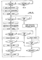
- the public switched telephone network or PSTN provides an incoming call indication to the address required usually by application of a voltage to the line intended to cause the audible ringing common to most voice telephone terminal equipment.
- the PSTN will create a communication channel between the call originator and the destination.
- the answer detect unit 28 of Figure 2 detects the answer condition provided by the user equipment attached to the jack 23. This answer detect is communicated to the microprocessor.
- the microprocessor then acts to retrieve from the security key memory 212 operating frequencies which act as an identity interrogation signal for transmission on the line.
- the operating frequency signal is transmitted via the telephone interface 24 on the line to the remote location from which the call is originated.
- This operating frequency signal which is also stored in the memory of the originating unit acts as an interrogation signal requiring the originating unit to submit an identity signal as will be explained hereinafter.
- the microprocessor simultaneously with controlling the transmission of the ID interrogation signal starts a timer providing a period of time in which the required ID signal must be received.
- the ID signal On receipt of an ID signal within the required period of time, the ID signal is checked to be of a proper format and stored in the memory for future use.
- the microprocessor 20 then moves to extract from the memory one of the plurality of pass code requests for transmission through the interface 24.
- the memory 212 of the security key is arranged to provide sufficient amount of memory to store for example 500 pairs of 32 bit security codes and associated request signals. Thus the memory is divided into memory location pairs with each pair including a first signal which will be transmitted and a second signal which will be expected in reply.
- the microprocessor 20 is arranged so that it looks in the memory to each pair in turn and extracts from that pair the request signal for transmission on the line.
- the key functions by receiving an address, in serial form, from the processor, decoding the address and returning the data at that address to the processor, also in serial form.
- the address information will be as large as it needs to be to uniquely select data from the key. This will be at least 24 bits but may need to be larger for some applications.
- the microprocessor again starts a timer circuit providing a short period of time in which it expects to receive the required security code.
- the microprocessor On receipt of a security code, the microprocessor acts to extract from the memory the security code associated in the memory with the request signal previously extracted. The processor then acts to compare the received security code with the expected security code. On obtaining a match between the security codes, the microprocessor acts to control the gate 30 through the driver 31 to open the transmission gate to allow communication between the network and the user equipment.
- the microprocessor In order therefore to obtain the necessary opening of the transmission gate, it is necessary for the microprocessor to initially receive an ID signal of the required format within a required period of time and subsequently to receive the required pass code or security code again within the required period of time.
- the microprocessor acts to monitor a disconnect of the communication channel and upon detecting such a disconnect acts to close the transmission gate. It is then in the position to receive a further incoming call and repeat the cycle. On such receipt of a further call, it will be appreciated that the unit follows the same procedure expect that it extracts from the memory unit the next pair of ID request signal and associated security code so that the signal and expected returned code are totally different and in no way connected with the signals previously issued.
- the microprocessor moves to the next step of issuing the pass code request. It cannot therefore act to open the transmission gate if the ID signal is not received in due time. Thus if the response is not received in time, the device will proceed automatically to the pass code request but the pass code will not be checked and no communication will be allowed to the terminal equipment.
- the microprocessor includes a simple calculation algorithm for developing a false request signal similar to but different from the actual stored signals so as to avoid using an actual signal which could give out information.
- the device will always behave in the same way regardless of the information it is given in order to provide an unauthorized user with no information that might assist in by-passing the device. Similarly if the pass code is not received or is not received in time the microprocessor moves to the disconnect procedure and reverts to the idle state waiting for a new call.
- the device will leave idle state upon the detection of an outgoing call originating at the terminal equipment with which the unit is associated and acts to fetch the operating frequencies. It then acts to look for the operating frequencies issued by the receiving unit and on receipt of the ID interrogate signal will act to open the transmission gate and fetch the ID from the memory and to transmit the ID on the line via the interface 24. It will then enter a wait loop for the pass code request from the receiving unit. When the request is received, the microprocessor 20 will act to retrieve and send from the memory the pass code associated with the ID request signal in the memory.
- the microprocessor on failing to find a match in the memory acts to generate, by an algorithm a false pass code which is then sent to avoid the release of information about the system.
- the unit then remains in connected state until it detects a disconnect of the communication channel following which it will close the transmission gate.
- the unit can act, as previously explained, either as a receiving unit or as an originating unit and the microprocessor acts accordingly to extract the relevant information from the memory as required.
- the indicators associated with the microprocessor 20 are arranged to be driven briefly when the equipment attached to the unit is taken off hook so that the unit extracts power from the telephone line for a short period of time sufficient to drive the indicators briefly for observation by the user.
- the first of the indicators shown at 341 is used to indicate when all of the memory locations in the memory have been used once that is all of the pairs of request signals and associated security codes have been used and thus will be repeated if the unit continues to use the same memory storage.
- the second indicator shown at 342 will be illuminated if the unit detects receipt of a security code which fails to properly match with the expected security code. This will indicate that an unauthorized user has attempted to breach the security and has failed to do so.
- the third indicator shown at 343 is used to show that a newly introduced key has previously been read as will be explained in more detail hereinafter.
- the test button 36 is used to reset the indicators 341, 342 and 343 so that after the information has been extracted the indicators revert to their initial condition.
- FIG. 6 there is shown a rack unit for storing a plurality of security units each of the type shown in Figure 2.
- a rack unit is generally indicated at 50 and is used in conjunction with a multi-port access terminal so that each unit is associated with a respective one of a plurality of telephone lines.
- the units each act in the manner previously described but can be coupled together so as to provide on a common bus information concerning the received ID signals, times of connect and times of disconnect and also the information concerning improper pass codes.
- Such a rack unit can comprise simple receiving areas 51 for a circuit board 52 so that the unit can be provided without the necessary housing necessary for a single unit.
- the rack unit can then be coupled to a conventional printer or other data equipment to print out information extracted from the individual units. Such information can be used for keeping a record of access by various authorized users by way of their received ID for billing or other purposes.
- this key is mounted in a housing 215 so that it is separable from the unit itself and thus a complete set of identical keys can be obtained for a group of the units and introduced or replaced whenever necessary.
- a complete set of identical keys can be obtained for a group of the units and introduced or replaced whenever necessary.
- the security logic circuit 211 controls the reading and writing of the pairs of request signals and security codes within the memory storage.
- the security logic circuit is arranged so that after writing the required information into the memory it can receive a seal command which acts to prevent the security logic circuit re-transmitting the information from the memory storage.
- FIG. 7 a simple circuit diagram is shown for the security logic circuit of Figure 3.
- the circuit includes the connnector 210 for connection to the connector 21 of the main unit.
- the connector 210 includes a first line 216 and a second line 217 indicated as “seal” and “unseal” respectively which are connected to a pair of flip flops 218 which in conventional manner have two separate states indicated at 0 and 1 respectively.
- the outputs of the two separate flip flops 219 and 220 of the pair 218 are coupled at 221 and 222 to an exclusive or-gate 223 of conventional form.
- the output from the exclusive or-gate 223 indicated at 224 acts to enable or disable the memory or RAM 212 depending upon the output on the line 224, that is a state 0 acts to enable the RAM and a state 1 to disable the RAM.
- the key further includes a battery 225 which is connected through the connector 210/21 to provide power to the memory 212 for retaining the memory when the device is disconnected from the main unit.
- a secondary power from the unit is provided on the line 226 through a regulator 227 so that the battery power is only used for storage when the key is disconnected.
- the flip flops 218 can only be reset via a reset unit 228 so that once switched from 0 state to the 1 state remain in that state until reset.
- both the flip flops are at 0 state-thus providing a state 0 on the line 224 to enable connection to the memory 212.
- the link indicated at 230 is disconnected and the line 224 is at state 0, hence there is no power to the memory.
- the key is inserted into the unit thus completing the connection at 230 and providing power to the memory or RAM 212.
- the memory can be written with the necessary information and the memory re-read to provide a verification of the necessary information.
- a seal command can be supplied on the line 216 from the main writing unit thus putting the first flip flop 219 into a state 1.
- the line 224 thus turns to the state 1 disabling the RAM.
- Power to the RAM is supplied by the battery 225 through a line 231, or-gate 223 and line 224.
- the key When received at the remote destination for usage, the key is inserted into the unit and connected thus to the connector 21.
- the first action of the security unit on receiving a telephone call that is if the hand set is Lifted at the user equipment, is to attempt to read the memory.
- An indicator on the security unit is illuminated to show that the unit is unable to read the memory so that the user can immediately see if the memory can be read. If the memory can be read it has thus received an unseal command as explained hereinafter and thus has been or may have been read and thus is no longer secure.
- the pressing of the button 36 acts to send an unseal command on the line 217 thus changing the state of the flip flop 220 to a state 1 which provides a state 0 on the line 224 thus enabling the RAM.
- Power to the RAM is supplied at this stage via the regulator 227 and the link 230.
- the security key can thus continue to be used while connected to the security unit and provides the memory as previously explained.
- the flip flops 218 can only be reset subsequent to complete erasing of the memory through the reset unit 228.
- the unit 228 only acts upon the removal of power from and subsequent restoration of power to the RAM and thus once the flip flop 220 has been changed to the state 1, it cannot be reverted to state 0 without erasing the memory.
- This technique does therefore not necessarily prevent the memory being read but certainly provides an indication in a simple manner that it may have been or has been read whereupon immediate knowledge is obtained of the breach of security following which all of the keys including that memory can be re-written with fresh information.
- the telecommunications security device therefore provides a number of advantages. Firstly it is resistant from any communication based break-in attempt including those involving line tapping since recording of previous information gives no details whatever concerning later required passwords. Secondly the unit is completely user transparent that is no action is required by the user and it does not rely upon any memory of the user to actuate the transmission gate. Thirdly the unit does not in any way interfere with the use of the telephone equipment to communicate with other unsecured telephone addresses.
- the key arrangement itself and particularly the security system whereby the key records the receipt of the necessary command to read the key can be used with other equipment following suitable modification to the stored memory and logic circuit as will be apparent to one skilled in the art.
- Such other equipment could be encryption devices where the necessary code for the encryption is stored in the memory and can be replaced by replacement or re-writing of the memory.
- the security logic circuit or the main unit microprocessor includes means for generating a number similar to a security code when a signal similar to a security code request signal is received.
- the security logic circuit or the main unit microprocessor includes means for generating a number similar to a security code when a signal similar to a security code request signal is received.
- information stored in the key can restrict operation of the associated unit to permit or deny incoming or outgoing calls as required.
Priority Applications (1)
| Application Number | Priority Date | Filing Date | Title |
|---|---|---|---|
| AT86301387T ATE81429T1 (de) | 1985-03-08 | 1986-02-26 | Geschuetztes fernmeldegeraet. |
Applications Claiming Priority (2)
| Application Number | Priority Date | Filing Date | Title |
|---|---|---|---|
| CA476147 | 1985-03-08 | ||
| CA000476147A CA1243791A (en) | 1985-03-08 | 1985-03-08 | Telecommunications security device |
Publications (3)
| Publication Number | Publication Date |
|---|---|
| EP0194782A2 true EP0194782A2 (de) | 1986-09-17 |
| EP0194782A3 EP0194782A3 (en) | 1988-08-03 |
| EP0194782B1 EP0194782B1 (de) | 1992-10-07 |
Family
ID=4129996
Family Applications (1)
| Application Number | Title | Priority Date | Filing Date |
|---|---|---|---|
| EP86301387A Expired - Lifetime EP0194782B1 (de) | 1985-03-08 | 1986-02-26 | Geschütztes Fernmeldegerät |
Country Status (5)
| Country | Link |
|---|---|
| EP (1) | EP0194782B1 (de) |
| JP (1) | JPS61274444A (de) |
| AT (1) | ATE81429T1 (de) |
| CA (1) | CA1243791A (de) |
| DE (1) | DE3686894T2 (de) |
Cited By (3)
| Publication number | Priority date | Publication date | Assignee | Title |
|---|---|---|---|---|
| EP0266044A2 (de) * | 1986-09-04 | 1988-05-04 | The Manitoba Telephone System | Fernmelde-Sicherheitssystem und Schlüsselspeichermodul dafür |
| EP0781017A1 (de) * | 1995-12-22 | 1997-06-25 | Ascom Monetel S.A. | System und Verfahren zur Verhinderung der betrügerischen Benutzung einer Fernsprechleitung unter Verwendung von Authentifizierungscodes |
| EP0903892A1 (de) * | 1997-09-12 | 1999-03-24 | Telefonaktiebolaget Lm Ericsson | Sicherheitsanordnung und Methode in einem Datenübertragungssystem |
Citations (3)
| Publication number | Priority date | Publication date | Assignee | Title |
|---|---|---|---|---|
| GB2062410A (en) * | 1979-10-25 | 1981-05-20 | Standard Telephones Cables Ltd | Call barring arrangement |
| US4430728A (en) * | 1981-12-29 | 1984-02-07 | Marathon Oil Company | Computer terminal security system |
| EP0115362A1 (de) * | 1983-01-24 | 1984-08-08 | Portenseigne | Anordnung zur Fernsprechverbindung durch Funkverbindung |
-
1985
- 1985-03-08 CA CA000476147A patent/CA1243791A/en not_active Expired
-
1986
- 1986-02-26 EP EP86301387A patent/EP0194782B1/de not_active Expired - Lifetime
- 1986-02-26 DE DE8686301387T patent/DE3686894T2/de not_active Expired - Fee Related
- 1986-02-26 AT AT86301387T patent/ATE81429T1/de not_active IP Right Cessation
- 1986-03-07 JP JP61048768A patent/JPS61274444A/ja active Granted
Patent Citations (3)
| Publication number | Priority date | Publication date | Assignee | Title |
|---|---|---|---|---|
| GB2062410A (en) * | 1979-10-25 | 1981-05-20 | Standard Telephones Cables Ltd | Call barring arrangement |
| US4430728A (en) * | 1981-12-29 | 1984-02-07 | Marathon Oil Company | Computer terminal security system |
| EP0115362A1 (de) * | 1983-01-24 | 1984-08-08 | Portenseigne | Anordnung zur Fernsprechverbindung durch Funkverbindung |
Non-Patent Citations (1)
| Title |
|---|
| NACHRICHTENTECHNISCHE ZEITSCHRIFT, vol. 36, no. 8, August 1983, pages 500-504, Berlin, DE; W. BOSCH: "Bildschirmtext braucht Datensicherheit" * |
Cited By (5)
| Publication number | Priority date | Publication date | Assignee | Title |
|---|---|---|---|---|
| EP0266044A2 (de) * | 1986-09-04 | 1988-05-04 | The Manitoba Telephone System | Fernmelde-Sicherheitssystem und Schlüsselspeichermodul dafür |
| EP0266044A3 (en) * | 1986-09-04 | 1990-07-18 | Computrex Centres Ltd. | Telecommunication security system and key memory module therefor |
| EP0781017A1 (de) * | 1995-12-22 | 1997-06-25 | Ascom Monetel S.A. | System und Verfahren zur Verhinderung der betrügerischen Benutzung einer Fernsprechleitung unter Verwendung von Authentifizierungscodes |
| FR2742950A1 (fr) * | 1995-12-22 | 1997-06-27 | Monetel | Systeme anti-fraude pour ligne telephonique |
| EP0903892A1 (de) * | 1997-09-12 | 1999-03-24 | Telefonaktiebolaget Lm Ericsson | Sicherheitsanordnung und Methode in einem Datenübertragungssystem |
Also Published As
| Publication number | Publication date |
|---|---|
| JPH0443454B2 (de) | 1992-07-16 |
| DE3686894D1 (de) | 1992-11-12 |
| EP0194782B1 (de) | 1992-10-07 |
| CA1243791A (en) | 1988-10-25 |
| JPS61274444A (ja) | 1986-12-04 |
| DE3686894T2 (de) | 1993-05-06 |
| ATE81429T1 (de) | 1992-10-15 |
| EP0194782A3 (en) | 1988-08-03 |
Similar Documents
| Publication | Publication Date | Title |
|---|---|---|
| CA1283187C (en) | Key management system for open communication environment | |
| US4531023A (en) | Computer security system for a time shared computer accessed over telephone lines | |
| US4779224A (en) | Identity verification method and apparatus | |
| EP0408041B1 (de) | Übertragungseinheit mit einer Funktion und einem Verfahren zur Anruferidentifizierung in einem digitalen Fernmeldenetz | |
| US4707804A (en) | Computer security system | |
| US4484306A (en) | Method and apparatus for controlling access in a data transmission system | |
| CN100334568C (zh) | 显示设备与包含该显示设备的资金交易设备 | |
| KR880000296B1 (ko) | 거래 처리 방식 | |
| JPH06125342A (ja) | 暗号化キーの識別および交換のための手段 | |
| EP0809171A1 (de) | Sicherheitsanordnung und -verfahren für einen Tastaturprozessor eines Transaktionsterminals | |
| US4475175A (en) | Computer communications control | |
| SE470149B (sv) | Anordning för åtkomst av tjänster via telefonapparat | |
| CN101626422A (zh) | 一种手机防盗方法 | |
| EP0194782B1 (de) | Geschütztes Fernmeldegerät | |
| CN1096802C (zh) | 无线电呼叫接收机 | |
| CA1270968A (en) | Automatic dialing apparatus for establishing connections between authorized subscribers | |
| JPH03160591A (ja) | プリペイドカード管理システム | |
| JP3083933B2 (ja) | 通信システム | |
| JPH0793254A (ja) | ネットワークシステムの悪用防止方法及び装置 | |
| GB2227906A (en) | Telephone call barring system | |
| JPS6155150B2 (de) | ||
| JPS60181887A (ja) | Icカ−ドの不正アクセス防止装置 | |
| JP2002242502A (ja) | 発信者番号通知を利用した電子錠制御方法、電子錠制御装置、プログラムおよび記録媒体 | |
| KR100334384B1 (ko) | 아이씨 카드 암호 검증기능을 갖는 공중전화기 및 그제어방법 | |
| JP2589825B2 (ja) | データ通信機能付公衆電話機 |
Legal Events
| Date | Code | Title | Description |
|---|---|---|---|
| PUAI | Public reference made under article 153(3) epc to a published international application that has entered the european phase |
Free format text: ORIGINAL CODE: 0009012 |
|
| AK | Designated contracting states |
Kind code of ref document: A2 Designated state(s): AT BE CH DE FR GB IT LI LU NL SE |
|
| PUAL | Search report despatched |
Free format text: ORIGINAL CODE: 0009013 |
|
| AK | Designated contracting states |
Kind code of ref document: A3 Designated state(s): AT BE CH DE FR GB IT LI LU NL SE |
|
| 17P | Request for examination filed |
Effective date: 19890202 |
|
| 17Q | First examination report despatched |
Effective date: 19910227 |
|
| GRAA | (expected) grant |
Free format text: ORIGINAL CODE: 0009210 |
|
| AK | Designated contracting states |
Kind code of ref document: B1 Designated state(s): AT BE CH DE FR GB IT LI LU NL SE |
|
| PG25 | Lapsed in a contracting state [announced via postgrant information from national office to epo] |
Ref country code: SE Effective date: 19921007 Ref country code: NL Effective date: 19921007 Ref country code: BE Effective date: 19921007 Ref country code: AT Effective date: 19921007 |
|
| REF | Corresponds to: |
Ref document number: 81429 Country of ref document: AT Date of ref document: 19921015 Kind code of ref document: T |
|
| REF | Corresponds to: |
Ref document number: 3686894 Country of ref document: DE Date of ref document: 19921112 |
|
| ITF | It: translation for a ep patent filed |
Owner name: DR. ING. A. RACHELI & C. |
|
| ET | Fr: translation filed | ||
| PG25 | Lapsed in a contracting state [announced via postgrant information from national office to epo] |
Ref country code: LU Free format text: LAPSE BECAUSE OF NON-PAYMENT OF DUE FEES Effective date: 19930228 |
|
| NLV1 | Nl: lapsed or annulled due to failure to fulfill the requirements of art. 29p and 29m of the patents act | ||
| PLBE | No opposition filed within time limit |
Free format text: ORIGINAL CODE: 0009261 |
|
| STAA | Information on the status of an ep patent application or granted ep patent |
Free format text: STATUS: NO OPPOSITION FILED WITHIN TIME LIMIT |
|
| 26N | No opposition filed | ||
| PGFP | Annual fee paid to national office [announced via postgrant information from national office to epo] |
Ref country code: GB Payment date: 19990305 Year of fee payment: 14 |
|
| PGFP | Annual fee paid to national office [announced via postgrant information from national office to epo] |
Ref country code: FR Payment date: 19990318 Year of fee payment: 14 |
|
| PGFP | Annual fee paid to national office [announced via postgrant information from national office to epo] |
Ref country code: CH Payment date: 19990412 Year of fee payment: 14 |
|
| PGFP | Annual fee paid to national office [announced via postgrant information from national office to epo] |
Ref country code: DE Payment date: 19990430 Year of fee payment: 14 |
|
| PG25 | Lapsed in a contracting state [announced via postgrant information from national office to epo] |
Ref country code: GB Free format text: LAPSE BECAUSE OF NON-PAYMENT OF DUE FEES Effective date: 20000226 |
|
| PG25 | Lapsed in a contracting state [announced via postgrant information from national office to epo] |
Ref country code: LI Free format text: LAPSE BECAUSE OF NON-PAYMENT OF DUE FEES Effective date: 20000229 Ref country code: CH Free format text: LAPSE BECAUSE OF NON-PAYMENT OF DUE FEES Effective date: 20000229 |
|
| REG | Reference to a national code |
Ref country code: CH Ref legal event code: PL |
|
| GBPC | Gb: european patent ceased through non-payment of renewal fee |
Effective date: 20000226 |
|
| PG25 | Lapsed in a contracting state [announced via postgrant information from national office to epo] |
Ref country code: FR Free format text: LAPSE BECAUSE OF NON-PAYMENT OF DUE FEES Effective date: 20001031 |
|
| PG25 | Lapsed in a contracting state [announced via postgrant information from national office to epo] |
Ref country code: DE Free format text: LAPSE BECAUSE OF NON-PAYMENT OF DUE FEES Effective date: 20001201 |
|
| REG | Reference to a national code |
Ref country code: FR Ref legal event code: ST |
|
| PG25 | Lapsed in a contracting state [announced via postgrant information from national office to epo] |
Ref country code: IT Free format text: LAPSE BECAUSE OF NON-PAYMENT OF DUE FEES;WARNING: LAPSES OF ITALIAN PATENTS WITH EFFECTIVE DATE BEFORE 2007 MAY HAVE OCCURRED AT ANY TIME BEFORE 2007. THE CORRECT EFFECTIVE DATE MAY BE DIFFERENT FROM THE ONE RECORDED. Effective date: 20050226 |