EP0194535A2 - Glühkerze mit einem schichtförmigen Heizwiderstand aus metallischen Siliziden - Google Patents
Glühkerze mit einem schichtförmigen Heizwiderstand aus metallischen Siliziden Download PDFInfo
- Publication number
- EP0194535A2 EP0194535A2 EP86102681A EP86102681A EP0194535A2 EP 0194535 A2 EP0194535 A2 EP 0194535A2 EP 86102681 A EP86102681 A EP 86102681A EP 86102681 A EP86102681 A EP 86102681A EP 0194535 A2 EP0194535 A2 EP 0194535A2
- Authority
- EP
- European Patent Office
- Prior art keywords
- resistive layer
- internal
- substrate
- external
- metallic
- Prior art date
- Legal status (The legal status is an assumption and is not a legal conclusion. Google has not performed a legal analysis and makes no representation as to the accuracy of the status listed.)
- Withdrawn
Links
Images

Classifications
-
- F—MECHANICAL ENGINEERING; LIGHTING; HEATING; WEAPONS; BLASTING
- F23—COMBUSTION APPARATUS; COMBUSTION PROCESSES
- F23Q—IGNITION; EXTINGUISHING-DEVICES
- F23Q7/00—Incandescent ignition; Igniters using electrically-produced heat, e.g. lighters for cigarettes; Electrically-heated glowing plugs
- F23Q7/001—Glowing plugs for internal-combustion engines
Definitions
- the invention is related to the field of electric heaters for the ignition of hydrocarbon fuels and in particular to a glow plug for internal combustion engines having a metallic silicide resistive film heater.
- glow plugs are currently used in compression ignited or Diesel type internal combustion engines to assist in the ignition of compressed air/fuel mixtures during cold starts.
- glow plugs are essential in the Northern states during the winter months when the ambient temperature falls below 10°C.
- the object of the invention is the substitution of a metallic-silicide film for the noble metal film which because of the higher resistivity of the metallic silicides permits the use of thicker resistive films which are less sensitive to the micro-irregularities of the ceramic structure, have a higher melting temperature which permits the glow plug to be operated at higher temperatures, and have a larger positive coefficient of resistance potentially making the glow plug self-limiting reducing the requirements of the attendant controller.
- the invention is a glow plug for internal combustion engines of the type having a metal shell, and an axial electrode disposed in the metal shell and electrically insulated therefrom, a heater member electrically connected between the metal shell and the axial electrode characterized by a cylindrical substrate and a continuous metallic-silicide resistive layer disposed on the surfaces of the cylindrical substrate.
- the substrate has an internal portion disposed in the shell and captivated between one end of the shell and the axial electrode, and an external portion protruding external to the shell.
- the metallic-silicide resistive layer is disposed along the internal and external surfaces of the cylindrical substrate and around the end of said external portion. The portion of the resistive layer disposed on the external surface of the substrate being in electrical contact with the metal shell and the portion of the resistive layer disposed on the internal surface being in electrical contact with the axial electrode.
- the advantages of the glow plug is that the interior of the cylindrically shaped heater member forms an extremely hot cul-de-sac which" is not cooled by the impinging air/fuel mixture. Another advantage is that the metallic-silicide resistive layer is relatively insensitive to oxidation and the corrosive atmosphere inside the engine. Another advantage is that the low mass of the heater member permits the glow plug to reach an operating temperature in less than 5 seconds with an applied power of less than 60 watts.
- the glow plug comprises a cylindrical metal shell 12 having an internal bore 14. Formed at one end of the shell 12 is a contact seat 16, defining a heater aperture 18 . Located in the internal bore 14 is a heater member 20 having a resistive metallic-silicide surface film heater element 24 coated or disposed on at least one surface of a non-conductive cylindrical substrate 22 as shall be described hereinafter.
- the non-conductive substrate 22 is preferably- a high temperature ceramic, such as alumina, but may be quartz, a high temperature glass or a metal sleeve coated with an insulating material.
- the cylindrical substrate 22 has an internal bore 26 passing therethrough, a base or internal portion 28 disposed in shell 12 and a smaller diameter external portion 3 0 protruding external to the shell 12 through the heater aperture 18.
- the heater aperture 18 has a diameter smaller than the diameter of the internal portion 28 of the substrate 22 and larger than the diameter of the external portion 30.
- An axial electrode 36 having a radial flange 38 and guide finger 40 formed at one end is received in the internal bore 26 of the cylindrical substrate 22 with the radial flange abutting the internal end face of the cylindrical substrate 22.
- the axial electrode 36 producing a force on the end of the cylindrical substrate 22 sufficient to deform an electrically conductive gasket 32 interposed between shoulder 34 of the cylindrical substrate 22 and the shell contact seat 16.
- the conductive gasket 32 may be copper, gold or any other maleable metal or alloy.
- a cylindrical insulator member 44 similar to the insulator commonly used in spark plugs, is inserted in bore 14 cicumscribing axial electrode 36 and abutting the opposite face of radial flange 38.
- the end of the shell 12 is crimped over to form a peripheral lip 46.
- the insulator member 44, axial electrode 36 and heater member 20 are then locked tightly inside of shell 12 by a hot press operation which heat then cools the undercut groove 95 while the compressive force is appplied between peripheral lip 46 and the opposing end 96 of an external hexagonal portion 50.
- the shell 12 further includes an externally threaded portion 48 for mounting the glow plug in the engine.
- the external hexagonal portion 50 facilitates threading the glow plug 10 into an appropriate threaded aperture of the engine.
- One advantage of the glow plug 10 shown in Figure 1 is that the electrical connections between the surface film heater element 24, the shell 12 and the axial electrode 36 are made internal to shell 12 where they are protected from the high temperatures and corrosive atmosphere inside the engine. This configuration eliminates the errosion problems of the electrical connections between the metallic silicide film, the shell 12 and the axial electrode 36.
- the heater member 20 has a generally cylindrical ceramic substrate '22 having an axial bore 26, an internal portion 28, a smaller diameter external portion 30 and a sloped shoulder 34 connecting the external surfaces of the internal portion 28 and external portion 30. Radii are provided at the edges at the substrate's end face 52 blending the end face 52 with the contiguous internal surface of bore 26 and the external surface 64 of the substrate or a full radius may be provided as shown. In a similar manner, a radius 54 is provided at the base of the substrate blending the end face 42 with the internal surface of bore 26.
- the metallic-silicide layer 24 may also be extended a short distance along the length of the external surface 60 of substrate 22 as shown.
- the opposite ends of the metallic-silicide layer 24 are electrically isolated by the uncoated region 56 of the external surface 60 and an uncoated peripheral region 58 of the end face 42.
- the metallic-silicide coating or film 24 may be applied to the desired surfaces of the substrate 22 by chemical vapor deposition techniques or any other method known in the art. Since the deposition techinques for metallic-silicide films have been extensively developed for low-resistance contacts in the solid state industry, it is not necessary to describe in detail how the metallic-silicide films are deposited for an understanding of the invention.
- the uncoated areas may be protected by mechanical shields during the deposition process.
- the entire substrate may be coated and the metallic-silicide layer removed from the insulator regions 56 and 58 by air abrasion.
- the interior of the cylindrical substrate after it has been coated with a metallic silicide may be filled with a dielectric material 65, such as alumina, to increase the structural strength of the ceramic substrate.
- highly conductive metal coating 66 and 68 may be applied over metallic silicide layer 24 disposed on the sloped shoulder 34 and the internal end face 42 respectively to assure good electrical contact between the metallic silicide surface layer 24, the heater seat 16, and the axial electrode 26, respectively.
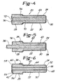
- the length of the axial bore 26 is completely filled with metallic-silicide material or other suitable conductive material to form an internal conductor 70 and the resistive metallic-silicide layer 24 is deposited along the length of the substrates external surfaces 34 and 64 and over the end 52 making electrical contact with the internal conductor 70 filling external bore 26.
- the internal conductor 70 filling the bore 26 may have a recess 72 formed at the end face 42 of the substrate 22 to receive the guide finger 40 of the axial electrode 36 and may be extended onto the end face 42 to provide a contact region 74 for the axial electrodes radial flange 38.
- the ceramic substrate may be formed directly around the axial electrode 36 and the resistive metallic-silicide film 24 deposited along the external surfaces 34 and 60 of the substrate 22 and over the end surface 74 of the axial electrode 36 as shown in Figure 5.
- the axial electrode 36 has a protrusion 76 adjacent to the interior portion 28 of the cylindrical substrate 22 to longitudinally lock the substrate 22 to the axial electrode 36 preventing any possible longitudinal shifting of the substrate 22 with respect to the axial electrode which would fracture or cause any electrical discontinuities at the junction between the metallic-silicide film 24 and the end face 78 of the axial electrode 36.
- a highly conductive metal coating such as coating 66, shown in Figure 3, may be deposited over the sloped shoulder 34 to assure good electrical contact between the shell 12 and the resistive metal-silicide layer 24.
- the cold resistance of the resistive metallic-silicide heater element 24 is between 0.2 and 0.6 ohms. which permits the heater member 20 to achieve an operating temperature of greater than 900°C with a current flow of less than 5 amperes when using a 12 volt source of electrical power, such as an automotive battery.
- the primary advantage of the cylindrical configuration of the heater member 20 shown on Figures 2 and 3 is that the bore 26 forms a high temperature cul-de-sac adjacent to its external end which is isolated from the cooling effects of the swirling air/fuel mixture in the engine's ignition chamber.
Landscapes
- Engineering & Computer Science (AREA)
- Chemical & Material Sciences (AREA)
- Combustion & Propulsion (AREA)
- Mechanical Engineering (AREA)
- General Engineering & Computer Science (AREA)
- Resistance Heating (AREA)
Applications Claiming Priority (2)
| Application Number | Priority Date | Filing Date | Title |
|---|---|---|---|
| US71322485A | 1985-03-15 | 1985-03-15 | |
| US713224 | 1985-03-15 |
Publications (2)
| Publication Number | Publication Date |
|---|---|
| EP0194535A2 true EP0194535A2 (de) | 1986-09-17 |
| EP0194535A3 EP0194535A3 (de) | 1988-01-07 |
Family
ID=24865294
Family Applications (1)
| Application Number | Title | Priority Date | Filing Date |
|---|---|---|---|
| EP86102681A Withdrawn EP0194535A3 (de) | 1985-03-15 | 1986-03-01 | Glühkerze mit einem schichtförmigen Heizwiderstand aus metallischen Siliziden |
Country Status (6)
| Country | Link |
|---|---|
| EP (1) | EP0194535A3 (de) |
| JP (1) | JPS61213512A (de) |
| AU (1) | AU5436686A (de) |
| BR (1) | BR8601457A (de) |
| CA (1) | CA1252830A (de) |
| ES (1) | ES8701952A1 (de) |
Cited By (2)
| Publication number | Priority date | Publication date | Assignee | Title |
|---|---|---|---|---|
| FR2641156A1 (de) * | 1988-12-24 | 1990-06-29 | Bosch Gmbh Robert | |
| EP0648977A3 (de) * | 1993-10-15 | 1995-08-16 | Beru Werk Ruprecht Gmbh Co A | Glühkerze. |
Family Cites Families (5)
| Publication number | Priority date | Publication date | Assignee | Title |
|---|---|---|---|---|
| US3912905A (en) * | 1974-02-25 | 1975-10-14 | Kanthal Corp | Electric resistance heating device |
| US4418661A (en) * | 1981-02-07 | 1983-12-06 | Robert Bosch Gmbh | Glow plug, particularly for diesel engine |
| DE3237922A1 (de) * | 1982-10-13 | 1984-04-19 | Robert Bosch Gmbh, 7000 Stuttgart | Gluehkerze fuer brennkraftmaschinen mit fremdzuendung |
| EP0129676B1 (de) * | 1983-06-23 | 1987-07-08 | Allied Corporation | Glühkerze mit einem schichtförmigen Heizwiderstand |
| JPS613922A (ja) * | 1984-06-18 | 1986-01-09 | Jidosha Kiki Co Ltd | デイ−ゼルエンジン用グロ−プラグ |
-
1986
- 1986-03-01 EP EP86102681A patent/EP0194535A3/de not_active Withdrawn
- 1986-03-04 CA CA000503183A patent/CA1252830A/en not_active Expired
- 1986-03-06 AU AU54366/86A patent/AU5436686A/en not_active Abandoned
- 1986-03-14 BR BR8601457A patent/BR8601457A/pt unknown
- 1986-03-14 JP JP5514086A patent/JPS61213512A/ja active Pending
- 1986-03-14 ES ES553026A patent/ES8701952A1/es not_active Expired
Cited By (3)
| Publication number | Priority date | Publication date | Assignee | Title |
|---|---|---|---|---|
| FR2641156A1 (de) * | 1988-12-24 | 1990-06-29 | Bosch Gmbh Robert | |
| EP0648977A3 (de) * | 1993-10-15 | 1995-08-16 | Beru Werk Ruprecht Gmbh Co A | Glühkerze. |
| US5589091A (en) * | 1993-10-15 | 1996-12-31 | Beru Ruprecht Gmbh & Co. Kg | Glow plug with prestressed contact surfaces |
Also Published As
| Publication number | Publication date |
|---|---|
| CA1252830A (en) | 1989-04-18 |
| BR8601457A (pt) | 1986-12-09 |
| JPS61213512A (ja) | 1986-09-22 |
| ES8701952A1 (es) | 1986-12-01 |
| ES553026A0 (es) | 1986-12-01 |
| EP0194535A3 (de) | 1988-01-07 |
| AU5436686A (en) | 1986-09-18 |
Similar Documents
| Publication | Publication Date | Title |
|---|---|---|
| US4816643A (en) | Glow plug having a metal silicide resistive film heater | |
| CN101490408B (zh) | 高功率放电燃料点火器 | |
| EP0098035B1 (de) | Elektrische selbstaufheizende Schnellglühstiftkerze | |
| US6881930B2 (en) | Glow plug and method of manufacturing the same | |
| US4418661A (en) | Glow plug, particularly for diesel engine | |
| US5589091A (en) | Glow plug with prestressed contact surfaces | |
| US4545339A (en) | Glow plug having a conductive film heater | |
| US4563568A (en) | Diesel engine glow plug | |
| US4682008A (en) | Self-temperature control type glow plug | |
| KR19980080845A (ko) | 세라믹 히터 | |
| US6770850B2 (en) | Heater | |
| US4620512A (en) | Glow plug having a conductive film heater | |
| US4582981A (en) | Glow plug having a resistive surface film heater | |
| EP0194535A2 (de) | Glühkerze mit einem schichtförmigen Heizwiderstand aus metallischen Siliziden | |
| WO2000019772A3 (de) | Keramische glühstiftkerze | |
| US4620511A (en) | Glow plug having a conductive film heater | |
| CA1230937A (en) | Glow plug having a resistive surface film heater | |
| JP3351573B2 (ja) | セラミック発熱体 | |
| ES8604705A1 (es) | Bujia de incandescencia para motores diesel | |
| US20060131295A1 (en) | Ceramic igniter | |
| EP1243859B1 (de) | Glühkerze zur Messung des Ionisationsstromes einer Kraftmaschine und sein Herstellungsverfahren | |
| JP2000266718A (ja) | 酸素センサ | |
| GB2136504A (en) | Flame glow-in plug for preheating the intake air of internal combustion engine | |
| JPH0259372B2 (de) | ||
| JP2892103B2 (ja) | ヒータ付スパークプラグ |
Legal Events
| Date | Code | Title | Description |
|---|---|---|---|
| PUAI | Public reference made under article 153(3) epc to a published international application that has entered the european phase |
Free format text: ORIGINAL CODE: 0009012 |
|
| AK | Designated contracting states |
Kind code of ref document: A2 Designated state(s): DE FR GB IT SE |
|
| PUAL | Search report despatched |
Free format text: ORIGINAL CODE: 0009013 |
|
| AK | Designated contracting states |
Kind code of ref document: A3 Designated state(s): DE FR GB IT SE |
|
| STAA | Information on the status of an ep patent application or granted ep patent |
Free format text: STATUS: THE APPLICATION IS DEEMED TO BE WITHDRAWN |
|
| 18D | Application deemed to be withdrawn |
Effective date: 19880708 |
|
| RIN1 | Information on inventor provided before grant (corrected) |
Inventor name: ZULAUF, GARY BYRON Inventor name: WEBER, DAVID CHARLES |