EP0194503B1 - Intake system for internal combustion engines - Google Patents
Intake system for internal combustion engines Download PDFInfo
- Publication number
- EP0194503B1 EP0194503B1 EP86102441A EP86102441A EP0194503B1 EP 0194503 B1 EP0194503 B1 EP 0194503B1 EP 86102441 A EP86102441 A EP 86102441A EP 86102441 A EP86102441 A EP 86102441A EP 0194503 B1 EP0194503 B1 EP 0194503B1
- Authority
- EP
- European Patent Office
- Prior art keywords
- intake
- control valve
- passage
- valve means
- intake system
- Prior art date
- Legal status (The legal status is an assumption and is not a legal conclusion. Google has not performed a legal analysis and makes no representation as to the accuracy of the status listed.)
- Expired - Lifetime
Links
Images




Classifications
-
- F—MECHANICAL ENGINEERING; LIGHTING; HEATING; WEAPONS; BLASTING
- F02—COMBUSTION ENGINES; HOT-GAS OR COMBUSTION-PRODUCT ENGINE PLANTS
- F02B—INTERNAL-COMBUSTION PISTON ENGINES; COMBUSTION ENGINES IN GENERAL
- F02B29/00—Engines characterised by provision for charging or scavenging not provided for in groups F02B25/00, F02B27/00 or F02B33/00 - F02B39/00; Details thereof
- F02B29/08—Modifying distribution valve timing for charging purposes
- F02B29/083—Cyclically operated valves disposed upstream of the cylinder intake valve, controlled by external means
-
- F—MECHANICAL ENGINEERING; LIGHTING; HEATING; WEAPONS; BLASTING
- F02—COMBUSTION ENGINES; HOT-GAS OR COMBUSTION-PRODUCT ENGINE PLANTS
- F02B—INTERNAL-COMBUSTION PISTON ENGINES; COMBUSTION ENGINES IN GENERAL
- F02B27/00—Use of kinetic or wave energy of charge in induction systems, or of combustion residues in exhaust systems, for improving quantity of charge or for increasing removal of combustion residues
-
- F—MECHANICAL ENGINEERING; LIGHTING; HEATING; WEAPONS; BLASTING
- F02—COMBUSTION ENGINES; HOT-GAS OR COMBUSTION-PRODUCT ENGINE PLANTS
- F02B—INTERNAL-COMBUSTION PISTON ENGINES; COMBUSTION ENGINES IN GENERAL
- F02B27/00—Use of kinetic or wave energy of charge in induction systems, or of combustion residues in exhaust systems, for improving quantity of charge or for increasing removal of combustion residues
- F02B27/02—Use of kinetic or wave energy of charge in induction systems, or of combustion residues in exhaust systems, for improving quantity of charge or for increasing removal of combustion residues the systems having variable, i.e. adjustable, cross-sectional areas, chambers of variable volume, or like variable means
- F02B27/0205—Use of kinetic or wave energy of charge in induction systems, or of combustion residues in exhaust systems, for improving quantity of charge or for increasing removal of combustion residues the systems having variable, i.e. adjustable, cross-sectional areas, chambers of variable volume, or like variable means characterised by the charging effect
- F02B27/0215—Oscillating pipe charging, i.e. variable intake pipe length charging
- F02B27/0221—Resonance charging combined with oscillating pipe charging
-
- F—MECHANICAL ENGINEERING; LIGHTING; HEATING; WEAPONS; BLASTING
- F02—COMBUSTION ENGINES; HOT-GAS OR COMBUSTION-PRODUCT ENGINE PLANTS
- F02B—INTERNAL-COMBUSTION PISTON ENGINES; COMBUSTION ENGINES IN GENERAL
- F02B27/00—Use of kinetic or wave energy of charge in induction systems, or of combustion residues in exhaust systems, for improving quantity of charge or for increasing removal of combustion residues
- F02B27/02—Use of kinetic or wave energy of charge in induction systems, or of combustion residues in exhaust systems, for improving quantity of charge or for increasing removal of combustion residues the systems having variable, i.e. adjustable, cross-sectional areas, chambers of variable volume, or like variable means
- F02B27/0294—Actuators or controllers therefor; Diagnosis; Calibration
-
- F—MECHANICAL ENGINEERING; LIGHTING; HEATING; WEAPONS; BLASTING
- F02—COMBUSTION ENGINES; HOT-GAS OR COMBUSTION-PRODUCT ENGINE PLANTS
- F02B—INTERNAL-COMBUSTION PISTON ENGINES; COMBUSTION ENGINES IN GENERAL
- F02B29/00—Engines characterised by provision for charging or scavenging not provided for in groups F02B25/00, F02B27/00 or F02B33/00 - F02B39/00; Details thereof
-
- F—MECHANICAL ENGINEERING; LIGHTING; HEATING; WEAPONS; BLASTING
- F02—COMBUSTION ENGINES; HOT-GAS OR COMBUSTION-PRODUCT ENGINE PLANTS
- F02B—INTERNAL-COMBUSTION PISTON ENGINES; COMBUSTION ENGINES IN GENERAL
- F02B29/00—Engines characterised by provision for charging or scavenging not provided for in groups F02B25/00, F02B27/00 or F02B33/00 - F02B39/00; Details thereof
- F02B29/08—Modifying distribution valve timing for charging purposes
-
- Y—GENERAL TAGGING OF NEW TECHNOLOGICAL DEVELOPMENTS; GENERAL TAGGING OF CROSS-SECTIONAL TECHNOLOGIES SPANNING OVER SEVERAL SECTIONS OF THE IPC; TECHNICAL SUBJECTS COVERED BY FORMER USPC CROSS-REFERENCE ART COLLECTIONS [XRACs] AND DIGESTS
- Y02—TECHNOLOGIES OR APPLICATIONS FOR MITIGATION OR ADAPTATION AGAINST CLIMATE CHANGE
- Y02T—CLIMATE CHANGE MITIGATION TECHNOLOGIES RELATED TO TRANSPORTATION
- Y02T10/00—Road transport of goods or passengers
- Y02T10/10—Internal combustion engine [ICE] based vehicles
- Y02T10/12—Improving ICE efficiencies
Definitions
- the present invention relates to an engine intake system, and more particularly to an engine intake system wherein a compression wave produced in the intake passage is utilized to increase the intake charge.
- Ch-A 177 862 discloses an intake system for an internal combustion engine comprising intake passage means leading to working chamber means of the engine, control valve means provided in said intake passage means for cyclically opening said intake passage means, timing control means for transmitting rotation of an engine output shaft to said control valve to operate said control valve means synchronously with rotation of the engine and retarding opening timing of the control valve means so that the control valve means is opened at a timing a predetermined time later than a top dead center of the working chamber means.
- Ep-A 0 141 165 A very similar intake system to this is known from Ep-A 0 141 165 which has an earlier priority date but which has not been published earlier than the priority date of the invention.
- Japanese patent application 54-12817 filed on February 8, 1979 and disclosed for public inspection on August 16, 1980 under the disclosure number 55-107018 proposes an engine intake system including an intake air reservoir provided in the intake passage, and a control valve located in the intake passage between the reservoir and the intake valve.
- the control valve includes a valve disc which is rotated at a speed which is the same as or one-half of the speed of the engine crankshaft so that the communication between the reservoir and the cylinder is controlled is accordance with the engine speed.
- the engine speed N in which the intake charge can effectively increase through a utilization of the compression wave can be represented by the following formula (1). wherein: ee is the effective valve opening period in degree, and v is the natural frequency in Hz of the intake system while the intake valve is open.
- the effective valve opening period is defined as the period wherein the intake gas is actually drawn into the combustion chamber and does not exactly conform to the actual valve opening period.
- the opening period of the control valve is controlled within the opening period of the intake valve so that the effective valve opening period corresponds to the opening period of the control valve.
- the Japanese patent application teaches to control the opening timing of the control valve in accordance with the engine speed to thereby change the timing in which the pressure wave is produced.
- the proposed intake system is therefore effective to a certain extent to expand the engine speed range in which the compression wave can be utilized to increase the intake charge.
- the opening period of the control valve is always within the opening period of the intake valve and the effective valve opening period ee remains unchanged. Further, the natural frequency v of the intake system does not change. Therefore, it is only possible within the opening period of the intake valve to expand the speed range in which the intake charge can be increased. Thus, the proposed system can perform an improvement only to a limited extent.
- the Japanese patent application teaches to retard the opening timing of the control valve in the low speed range so that the pressure wave can be intensified, however, this arrangement will cause an increase in the pumping loss. Thus, there will be an adverse effect on the fuel economy in light load engine operation.
- a further problem in the proposed system is that the effetive valve opening period is determined essentially by the control valve which has the opening period smaller than that of the intake valve, so that the control valve produces an additional resistance to the intake flow. Therefore, it becomes difficult to ensure an adequate intake charge in a high speed, heavy load engine operation.
- Another object of the present invention is to provide an engine intake system in which the intake charge can be increased without sacrificing other properties.
- the opening timing of the control valve means is retarded under a low speed, high load engine operation so that the control valve means is opened later than the intake top dead center of the working chamber means.
- a strong negative pressure is produced in the intake passage means downstream the control valve means before the control valve means is opened.
- the negative pressure propagates toward upstream side in the intake passage means and reversed at the reversing means to produce a positive pressure which is then transmitted toward downstream side and reaches the working chamber means at the end period of the intake stroke. It is therefore possible to accomplish a high intake charge.
- the opening timing of the control valve means is advanced. Since the closing timing of the control valve means can be well after the end timing of the intake stroke, the advance in the opening timing of the control valve means causes an increase in the effective valve opening period. It is therefore possible to prevent any increase in the resistance to the intake flow under a high speed engine operation.
- the dynamic effect of the intake system can be utilized for increasing the intake charge.
- control valve means it is also preferable to make the control valve means ineffective under a light load operation because the control valve means can cause an increase in the pumping loss. According to the present invention, it is therefore possible to increase the intake charge under a wide engine operating range.
- a four-cylinder engine 1 including a cylinder block 2 formed with four cylinder bores 3.
- a piston 4 for reciprocating movement.
- a cylinder head 5 which is secured to the cylinder block 2.
- a combustion chamber 6 is defined in each cylinder bore 3 in the cylinder block 2.
- the cylinder head 5 is formed with an intake port 7 and exhause port 8 which open to each cylinder bore 3.
- the cylinder head 5 is further formed with an intake passage 9 and an exhause passage 10 which respectively communicate with the intake port 7 and the exhaust port 8.
- the intake port 7 is provided with an intake valve 11 and the exhaust port 8 is provided with an exhaust valve 12.
- an ignition plug 12a for each combustion chamber 6.
- a fuel injection valve 12b is provided in each intake passage 9.
- the intake passages 9 communicate with a main intake passage 13 which is provided at the upstream end with an air cleaner 14. Downstream the air cleaner 14, there are provided in this order an airflow meter 15 and a throttle valve 17.
- the main intake passage 13 has an intake air tank 16 which provides the main intake passage 13 with an additional volume. Downstream the throttle valve 17, there is provided a rotary type control valve 18 which is specifically shown in Figure 3. A bypass passage 19 is provided for connecting the main intake passage 13 downstream the throttle valve 17 with the individual intake passage 9 bypassing the control valve 18 as shown in Figure 1.
- the bypass passage 19 has a bypass valve 20 for controlling the communication between the bypass passage 19 and the individual intake passages 9.
- the rotary valve 18 is of a hollow cylindrical configuration having a cylindrical wall formed with openings 21 corresponding to the respective intake passages 9 so that the inside of the valve 18 is cyclically opened to the passages 9 at an appropriate timing as the valve 18 is rotated synchronously with the engine rotation.
- the ignition takes place in the oder of No. 1, No. 3, No. 4 and No. 2 cylinders so that the openings 21 for the No. 1 and No. 4 cylinders and the openings 21 for the No. 2 and No. 3 cylinders are located respectively at the same angular positions.
- the rotary valve 18 has a drive shaft 18a which is connected through a timing mechanism 22 with a pulley 23.
- the engine 1 has an output shaft 24 which carries a driving pulley 25.
- An endless belt 26 is passed around the pulleys 23 and 25 so that a rotation of the engine output shaft 24 is transmitted to the pulley 23 and then through the timing mechanism 22 to the shaft 18a of the rotary valve 18 to drive the same.
- the pulleys 23 and 25 has the same diameter so that the rotary valve 18 is rotated at the same speed as the engine output shaft 24.
- the timing mechanism 22 includes a helical gear 27 secured to the shaft 23a of the pulley 23 and a helical gear 28 secured to the shaft 18a of the rotary valve 18,
- the gears 27 and 28 are opposed to each other and an adjusting dog 29 is in meshing engagement with the helical gears 27 and 28.
- the rotation of the pulley 23 is therefore transmitted through the gear 27, the dog 29 and the gear 28 to the rotary valve 18.
- the dog 29 is displaceable in the axial direction and through such axial displacement, it is possible to change the angular phase of the gear 28 with respect to that of the gear 27.
- an actuator 30 which is of a type that is operated under the signal of an electronic control unit 31 preferably comprising a microprocessor.
- the control unit 31 receives an engine speed signal from a speed detector 31a and an engine load signal from a load detector 31 b.
- the control unit 31 determines the opening timing of the control valve 18 and operates the actuator 30 so that the desired valve opening timing is detained.
- the bypass valve 20 is provided with an actuator 20a.
- the control unit 31 produces an output signal based on the engine speed signal and the engine load signal and makes the actuator 20a to operate so that the bypass valve 20 is opened under desired engine operating conditions.
- the opening period of the rotary valve 18 is substantially the same as that of the intake valve 11.
- the opening timing of the rotary valve 18 is substantially the same as that of the intake valve 11 so that the rotary valve 18 is opened substantially in the period wherein the intake valve 11 is opened as shown by dotted lines in Figure 4(b).
- the opening timing of the rotary valve 18 is retarded as shown by full lines so that the rotary valve 18 is opened after the intake top dead center. It will therefore be understood that, by the time when the control valve 18 is opened, a negative pressure is produced in the intake passage 9 downstream the control valve 18.
- the negative pressure propagates through the main passage 13 to the position where the tank 16 is provided.
- the negative pressure is reversed and a positive pressure is produced.
- the intake system is designed so that the positive pressure thus produced is transmitted to the intake port 7 at the end period of the intake stroke to increase the intake charge.
- the opening timing of the control valve 18 is retarded so that it open after the intake top dead center under a low speed engine operation wherein the suction pressure is relatively weak.
- the illustrated intake system is further advantageous in that the effective valve opening period can be changed. Therefore, it is possible to accomplish an effective intake charge increase in a relatively wide engine operating speed range.
- the actuator 20a Under a high speed, heavy load range, the actuator 20a is operated to open the bypass valve 20 so that the intake air is drawn not only through the control valve 18 but also through the bypass valve 20.
- This control will be effective to decrease the resistance to the intake flow so that an increased intake flow is obtained for the high speed, heavy load operation. It is of course advisable to open the bypass valve 20 under a low speed, light load operation. This will be effective to decrease the pumping loss.
- Figure 4(b) shows the relationship between the valve overlap ee and the brake mean effective pressure Pe. It will be understood that, by properly determining the valve overlap, it is possible to obtain a significant increase in the engine output torque.
- the embodiment shown therein includes a rotary valve 18' which is provided in the individual intake passages 9. There is further formed a negative wave reversing tank 16' between the main intake passage 13 and the individual intake passages 9.
- the rotary valve 18' has diametrically extending openings 21' to cyclically open the passages 9.
- the valve 18' is rotated at a speed which is one-half the speed of the engine output shaft 24.
- the driven pulley 23' has a diameter which is two times as large as the drive pulley 25.
- a bypass passage 19 is provided to connect together the individual intake passage 9 and a bypass valve 20 is provided in the bypass passage 19.
- the engine shown therein includes a bypass passage 19 having an upstream end 19a opened to the tank 16.
- the bypass passage 19 is branched and each of the branched passages is opened at the downstream end 19b to each individual intake passage 9.
- a bypass valve 20 which is adapted to be operated by a pneumatic actuator 30.
- the actuator 30 includes a diaphragm 30a connected with the valve 20.
- a suction pressure chamber 30b which is connected through a suction line 31 to the bypass passage 19.
- there is a spring 30c which forces the diaphragm 30a in the direction of closing the valve 20.
- the diaphragm 30a When a suction pressure is drawn into the chamber 30b, the diaphragm 30a is displaced to open the valve 20.
- the suction pressure is introduced into the chamber 30b from the tank 16 through the bypass passage 19 and the suction line 30d.
- the valve 20 is closed when the suction pressure is weak but opened when the suction pressure is intensified beyond a predetermined level.
- the engine shown therein includes an intake system which is divided into two groups taking into consideration the order of ignition.
- the individual intake passages 9 for the No. 1 and No. 4 cylinders are connected with an intermediate passage 9a.
- the individual intake passages for the No. 2 and No. 4 cylinders are connected with another intermediate passage 9a.
- the intermediate passages 9a are connected together by a manifold 9b which is in turn connected with a main intake passage 13.
- the passages 9a are respectively provided with throttle valves 17.
- the arrangements are the same as in the embodiment shown in Figures 5 and 6.
- the negative pressure in one intermediate passage 9a is different in phase by one-half of the cycle from the negative pressure in the other intermediate passage 9a. With this arrangement, it is also possible to reverse the negative pressure at the manifold 9b.
Landscapes
- Engineering & Computer Science (AREA)
- Chemical & Material Sciences (AREA)
- Combustion & Propulsion (AREA)
- Mechanical Engineering (AREA)
- General Engineering & Computer Science (AREA)
- Health & Medical Sciences (AREA)
- Biomedical Technology (AREA)
- Characterised By The Charging Evacuation (AREA)
Description
- The present invention relates to an engine intake system, and more particularly to an engine intake system wherein a compression wave produced in the intake passage is utilized to increase the intake charge.
- Hithertofore, it has been proposed to accomplish a high engine output by increasing the intake charge through a utilization of the inertia of the intake flow, the intake pressure resonance effect or the intake flow dynamic effect. In case where an increase in the intake charge is sought through a utilization of the pressure wave produced in the intake passage, several problems are encountered. One of such problems is that the pressure wave in the intake passage is weak under a low speed engine operation so that an adequate improvement cannot be achieved. Further, it is difficult to obtain improved results in increasing the intake charge through a broad engine operating range due to the fact that the compression wave propagates at the sonic speed but the engine speed changes in a wide range.
- Ch-A 177 862 discloses an intake system for an internal combustion engine comprising intake passage means leading to working chamber means of the engine, control valve means provided in said intake passage means for cyclically opening said intake passage means, timing control means for transmitting rotation of an engine output shaft to said control valve to operate said control valve means synchronously with rotation of the engine and retarding opening timing of the control valve means so that the control valve means is opened at a timing a predetermined time later than a top dead center of the working chamber means.
- A very similar intake system to this is known from Ep-A 0 141 165 which has an earlier priority date but which has not been published earlier than the priority date of the invention.
- In view of the foregoing problems, Japanese patent application 54-12817 filed on February 8, 1979 and disclosed for public inspection on August 16, 1980 under the disclosure number 55-107018 proposes an engine intake system including an intake air reservoir provided in the intake passage, and a control valve located in the intake passage between the reservoir and the intake valve. The control valve includes a valve disc which is rotated at a speed which is the same as or one-half of the speed of the engine crankshaft so that the communication between the reservoir and the cylinder is controlled is accordance with the engine speed.
- In general, the engine speed N in which the intake charge can effectively increase through a utilization of the compression wave can be represented by the following formula (1).

- The effective valve opening period is defined as the period wherein the intake gas is actually drawn into the combustion chamber and does not exactly conform to the actual valve opening period. According to the teachings by the aforementioned Japanese patent application, the opening period of the control valve is controlled within the opening period of the intake valve so that the effective valve opening period corresponds to the opening period of the control valve. The Japanese patent application teaches to control the opening timing of the control valve in accordance with the engine speed to thereby change the timing in which the pressure wave is produced. The proposed intake system is therefore effective to a certain extent to expand the engine speed range in which the compression wave can be utilized to increase the intake charge.
- It should however be noted that, in the proposed system, the opening period of the control valve is always within the opening period of the intake valve and the effective valve opening period ee remains unchanged. Further, the natural frequency v of the intake system does not change. Therefore, it is only possible within the opening period of the intake valve to expand the speed range in which the intake charge can be increased. Thus, the proposed system can perform an improvement only to a limited extent.
- It should further be noted that the Japanese patent application teaches to retard the opening timing of the control valve in the low speed range so that the pressure wave can be intensified, however, this arrangement will cause an increase in the pumping loss. Thus, there will be an adverse effect on the fuel economy in light load engine operation. A further problem in the proposed system is that the effetive valve opening period is determined essentially by the control valve which has the opening period smaller than that of the intake valve, so that the control valve produces an additional resistance to the intake flow. Therefore, it becomes difficult to ensure an adequate intake charge in a high speed, heavy load engine operation.
- It is therefore an object of the present invention to provide an engine intake system in which the compression wave produced in the intake passage can be utilized to increase the intake charge throughout a wide engine operating range.
- Another object of the present invention is to provide an engine intake system in which the intake charge can be increased without sacrificing other properties.
- According to the present invention, the above and other objects can be accomplished by an intake system for an internal combustion engine as described in
claim 1. - According to the features of the present invention, the opening timing of the control valve means is retarded under a low speed, high load engine operation so that the control valve means is opened later than the intake top dead center of the working chamber means. Thus, a strong negative pressure is produced in the intake passage means downstream the control valve means before the control valve means is opened. As soon as the control valve means is opened, the negative pressure propagates toward upstream side in the intake passage means and reversed at the reversing means to produce a positive pressure which is then transmitted toward downstream side and reaches the working chamber means at the end period of the intake stroke. It is therefore possible to accomplish a high intake charge.
- Under a high speed engine operating range, the opening timing of the control valve means is advanced. Since the closing timing of the control valve means can be well after the end timing of the intake stroke, the advance in the opening timing of the control valve means causes an increase in the effective valve opening period. It is therefore possible to prevent any increase in the resistance to the intake flow under a high speed engine operation. By determining the natural frequency of the intake system so that a preferable result can be obtained in the high speed range, the dynamic effect of the intake system can be utilized for increasing the intake charge.
- It is also preferable to make the control valve means ineffective under a light load operation because the control valve means can cause an increase in the pumping loss. According to the present invention, it is therefore possible to increase the intake charge under a wide engine operating range.
- The above and other objects and features of the present invention will becme apparent from the following descriptions of preferred embodiments taking reference to the accompanying drawings.
-
- Figure 1 is a diagrammatical top plan view of an engine in accordance with one embodiment of the present invention;
- Figure 2 is a vertical sectional view of the engine shown in Figure 1;
- Figure 3 is a perspective view showing the rotary type control valve;
- Figure 4(a) is a diagram showing the valve timings;
- Figure 4(b) is a diagram showing the relationship between the valve overlap ee and the brake mean effective pressure;
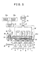
- Figure 5 is a view similar to Figure 1 but showing another embodiment;
- Figure 6 is a vertical sectional view of the engine shown in Figure 5;
- Figure 7 is a view similar to Figure 1 but showing a further embodiment;
- Figure 8 is a vertical sectional view of the engine shown in Figure 7;
- Figure 9 is a diagram showing the relationship between the valve opening and the intake suction pressure; and,
- Figure 10 is a top plan view of an engine in accordance with a further embodiment of the present invention.
- Referring to the drawings, particularly to Figures 1 and 2, there is shown a four-
cylinder engine 1 including acylinder block 2 formed with fourcylinder bores 3. In each of thecylinder bores 3, there is disposed apiston 4 for reciprocating movement. Above thecylinder block 2, there is acylinder head 5 which is secured to thecylinder block 2. Thus, acombustion chamber 6 is defined in eachcylinder bore 3 in thecylinder block 2. - The
cylinder head 5 is formed with anintake port 7 andexhause port 8 which open to each cylinder bore 3. Thecylinder head 5 is further formed with anintake passage 9 and anexhause passage 10 which respectively communicate with theintake port 7 and theexhaust port 8. Theintake port 7 is provided with anintake valve 11 and theexhaust port 8 is provided with anexhaust valve 12. In thecylinder head 5, there is also provided anignition plug 12a for eachcombustion chamber 6. Afuel injection valve 12b is provided in eachintake passage 9. Theintake passages 9 communicate with amain intake passage 13 which is provided at the upstream end with anair cleaner 14. Downstream theair cleaner 14, there are provided in this order anairflow meter 15 and athrottle valve 17. - The
main intake passage 13 has anintake air tank 16 which provides themain intake passage 13 with an additional volume. Downstream thethrottle valve 17, there is provided a rotarytype control valve 18 which is specifically shown in Figure 3. Abypass passage 19 is provided for connecting themain intake passage 13 downstream thethrottle valve 17 with theindividual intake passage 9 bypassing thecontrol valve 18 as shown in Figure 1. Thebypass passage 19 has abypass valve 20 for controlling the communication between thebypass passage 19 and theindividual intake passages 9. - As shown in Figure 3, the
rotary valve 18 is of a hollow cylindrical configuration having a cylindrical wall formed withopenings 21 corresponding to therespective intake passages 9 so that the inside of thevalve 18 is cyclically opened to thepassages 9 at an appropriate timing as thevalve 18 is rotated synchronously with the engine rotation. In the illustrated embodiment, the ignition takes place in the oder of No. 1, No. 3, No. 4 and No. 2 cylinders so that theopenings 21 for the No. 1 and No. 4 cylinders and theopenings 21 for the No. 2 and No. 3 cylinders are located respectively at the same angular positions. - In Figure 1, it will be noted that the
rotary valve 18 has adrive shaft 18a which is connected through atiming mechanism 22 with apulley 23. Theengine 1 has anoutput shaft 24 which carries a drivingpulley 25. Anendless belt 26 is passed around thepulleys engine output shaft 24 is transmitted to thepulley 23 and then through thetiming mechanism 22 to theshaft 18a of therotary valve 18 to drive the same. Thepulleys rotary valve 18 is rotated at the same speed as theengine output shaft 24. - The
timing mechanism 22 includes ahelical gear 27 secured to theshaft 23a of thepulley 23 and ahelical gear 28 secured to theshaft 18a of therotary valve 18, Thegears dog 29 is in meshing engagement with thehelical gears pulley 23 is therefore transmitted through thegear 27, thedog 29 and thegear 28 to therotary valve 18. Thedog 29 is displaceable in the axial direction and through such axial displacement, it is possible to change the angular phase of thegear 28 with respect to that of thegear 27. Thus, it is possible to control the opening timing of thecontrol valve 18 by an axial displacement of thedog 29. - In order to determine the axial position of the adjusting
dog 29, there is provided anactuator 30 which is of a type that is operated under the signal of anelectronic control unit 31 preferably comprising a microprocessor. Thecontrol unit 31 receives an engine speed signal from aspeed detector 31a and an engine load signal from aload detector 31 b. Thecontrol unit 31 determines the opening timing of thecontrol valve 18 and operates theactuator 30 so that the desired valve opening timing is detained. - The
bypass valve 20 is provided with anactuator 20a. Thecontrol unit 31 produces an output signal based on the engine speed signal and the engine load signal and makes theactuator 20a to operate so that thebypass valve 20 is opened under desired engine operating conditions. - Referring now to Figure 4(a), the opening period of the
rotary valve 18 is substantially the same as that of theintake valve 11. Under a high speed engine operation, the opening timing of therotary valve 18 is substantially the same as that of theintake valve 11 so that therotary valve 18 is opened substantially in the period wherein theintake valve 11 is opened as shown by dotted lines in Figure 4(b). Under a low speed engine operation, however, the opening timing of therotary valve 18 is retarded as shown by full lines so that therotary valve 18 is opened after the intake top dead center. It will therefore be understood that, by the time when thecontrol valve 18 is opened, a negative pressure is produced in theintake passage 9 downstream thecontrol valve 18. As soon as thecontrol valve 18 is opened, the negative pressure propagates through themain passage 13 to the position where thetank 16 is provided. At thetank 16, the negative pressure is reversed and a positive pressure is produced. The intake system is designed so that the positive pressure thus produced is transmitted to theintake port 7 at the end period of the intake stroke to increase the intake charge. - Since a strong positive pressure is produced at the
tank 16 when a strong negative pressure is produced before thecontrol valve 18 is opened, the opening timing of thecontrol valve 18 is retarded so that it open after the intake top dead center under a low speed engine operation wherein the suction pressure is relatively weak. The illustrated intake system is further advantageous in that the effective valve opening period can be changed. Therefore, it is possible to accomplish an effective intake charge increase in a relatively wide engine operating speed range. - Under a high speed, heavy load range, the
actuator 20a is operated to open thebypass valve 20 so that the intake air is drawn not only through thecontrol valve 18 but also through thebypass valve 20. This control will be effective to decrease the resistance to the intake flow so that an increased intake flow is obtained for the high speed, heavy load operation. It is of course advisable to open thebypass valve 20 under a low speed, light load operation. This will be effective to decrease the pumping loss. Figure 4(b) shows the relationship between the valve overlap ee and the brake mean effective pressure Pe. It will be understood that, by properly determining the valve overlap, it is possible to obtain a significant increase in the engine output torque. - Referring to Figures 5 and 6, the embodiment shown therein includes a rotary valve 18' which is provided in the
individual intake passages 9. There is further formed a negative wave reversing tank 16' between themain intake passage 13 and theindividual intake passages 9. In this embodiment, the rotary valve 18' has diametrically extending openings 21' to cyclically open thepassages 9. The valve 18' is rotated at a speed which is one-half the speed of theengine output shaft 24. Thus, the driven pulley 23' has a diameter which is two times as large as thedrive pulley 25. Abypass passage 19 is provided to connect together theindividual intake passage 9 and abypass valve 20 is provided in thebypass passage 19. - Referring now to Figures 7 and 8, the engine shown therein includes a
bypass passage 19 having anupstream end 19a opened to thetank 16. At the downstream side, thebypass passage 19 is branched and each of the branched passages is opened at thedownstream end 19b to eachindividual intake passage 9. In each branch passage of thebypass passage 19, there is provided abypass valve 20 which is adapted to be operated by apneumatic actuator 30. Theactuator 30 includes adiaphragm 30a connected with thevalve 20. At one side of thediaphragm 30a, there is defined asuction pressure chamber 30b which is connected through asuction line 31 to thebypass passage 19. In thechamber 30b, there is aspring 30c which forces thediaphragm 30a in the direction of closing thevalve 20. When a suction pressure is drawn into thechamber 30b, thediaphragm 30a is displaced to open thevalve 20. The suction pressure is introduced into thechamber 30b from thetank 16 through thebypass passage 19 and thesuction line 30d. As shown in Figure 9, thevalve 20 is closed when the suction pressure is weak but opened when the suction pressure is intensified beyond a predetermined level. - Referring to Figure 10, the engine shown therein includes an intake system which is divided into two groups taking into consideration the order of ignition. The
individual intake passages 9 for the No. 1 and No. 4 cylinders are connected with anintermediate passage 9a. Similarly, the individual intake passages for the No. 2 and No. 4 cylinders are connected with anotherintermediate passage 9a. Theintermediate passages 9a are connected together by a manifold 9b which is in turn connected with amain intake passage 13. Thepassages 9a are respectively provided withthrottle valves 17. In other respects, the arrangements are the same as in the embodiment shown in Figures 5 and 6. In this embodiment, the negative pressure in oneintermediate passage 9a is different in phase by one-half of the cycle from the negative pressure in the otherintermediate passage 9a. With this arrangement, it is also possible to reverse the negative pressure at the manifold 9b.
Claims (11)
Applications Claiming Priority (6)
| Application Number | Priority Date | Filing Date | Title |
|---|---|---|---|
| JP3453185 | 1985-02-25 | ||
| JP34531/85 | 1985-02-25 | ||
| JP22165185 | 1985-10-04 | ||
| JP221651/85 | 1985-10-04 | ||
| JP225513/85 | 1985-10-09 | ||
| JP22551385A JPH0672536B2 (en) | 1985-10-09 | 1985-10-09 | Engine intake system |
Publications (2)
| Publication Number | Publication Date |
|---|---|
| EP0194503A1 EP0194503A1 (en) | 1986-09-17 |
| EP0194503B1 true EP0194503B1 (en) | 1990-09-26 |
Family
ID=27288447
Family Applications (1)
| Application Number | Title | Priority Date | Filing Date |
|---|---|---|---|
| EP86102441A Expired - Lifetime EP0194503B1 (en) | 1985-02-25 | 1986-02-25 | Intake system for internal combustion engines |
Country Status (3)
| Country | Link |
|---|---|
| US (1) | US4738233A (en) |
| EP (1) | EP0194503B1 (en) |
| DE (1) | DE3674436D1 (en) |
Families Citing this family (41)
| Publication number | Priority date | Publication date | Assignee | Title |
|---|---|---|---|---|
| JPS6258016A (en) * | 1985-09-06 | 1987-03-13 | Kanesaka Gijutsu Kenkyusho:Kk | Intake device for engine |
| JPS63111227A (en) * | 1986-10-30 | 1988-05-16 | Mazda Motor Corp | Suction device for engine |
| DE3702827A1 (en) * | 1987-01-30 | 1988-08-11 | Bayerische Motoren Werke Ag | INTAKE SYSTEM WITH A CONTROL DEVICE, ESPECIALLY FOR COMBUSTION ENGINES |
| GB2202276B (en) * | 1987-03-09 | 1991-09-18 | Honda Motor Co Ltd | Intake device for internal combustion engine |
| GB2211889A (en) * | 1987-11-05 | 1989-07-12 | Keith Gordon Hall | Engine throttle valve |
| GB2210665B (en) * | 1987-10-07 | 1992-04-15 | Keith Gordon Hall | Engine intake system |
| GB2222632A (en) * | 1988-09-09 | 1990-03-14 | Ford Motor Co | Pressure wave control of i.c. engine charging |
| JP2753874B2 (en) * | 1989-12-06 | 1998-05-20 | マツダ株式会社 | Multi-cylinder engine intake system |
| JPH0436053A (en) * | 1990-05-30 | 1992-02-06 | Nissan Motor Co Ltd | Control device for intake air of internal combustion engine |
| DE4018612C2 (en) * | 1990-06-11 | 2003-04-30 | Audi Ag | Intake system for a multi-cylinder internal combustion engine |
| US5448971A (en) * | 1990-06-20 | 1995-09-12 | Group Lotus Limited | Internal combustion engine and an improved rotary inlet valve for use therewith |
| GB9013788D0 (en) * | 1990-06-20 | 1990-08-08 | Lotus Group Plc | Internal combustion engine and an improved rotary inlet valve for use therewith |
| US5105784A (en) * | 1991-04-08 | 1992-04-21 | General Motors Corporation | Rotary valve and system for duration and phase control |
| EP0538484B1 (en) * | 1991-05-08 | 1996-10-30 | Nippondenso Co., Ltd. | Intake control device for an internal combustion engine |
| US5197433A (en) * | 1992-04-30 | 1993-03-30 | Dykstra Gregory J | Anticipatory intake manifold tuning valve control |
| US5417188A (en) * | 1992-07-20 | 1995-05-23 | Schiattino; Miljenko | Double effect distribution sequential valve shaft assembly |
| US5355849A (en) * | 1992-07-20 | 1994-10-18 | Miljenko Schiattino | Automatic variator valve overlap or timing and valve section |
| US5211139A (en) * | 1992-09-08 | 1993-05-18 | Siemens Automotive Limited | Active manifold |
| DE4344504A1 (en) * | 1993-12-24 | 1995-06-29 | Audi Ag | Intake manifold system for a multi-cylinder internal combustion engine |
| JP3421731B2 (en) * | 1994-05-31 | 2003-06-30 | ヤマハ発動機株式会社 | Engine intake control device |
| US5582140A (en) * | 1995-05-04 | 1996-12-10 | Strieber; Louis C. | Rotatable timed mechanism for feeding vaporous fluid to a combustion cylinder |
| US6125819A (en) * | 1995-08-08 | 2000-10-03 | Strieber; Louis Charles | Rotating piston engine with variable effective compression stroke |
| DE19754287A1 (en) * | 1997-12-08 | 1999-06-10 | Bosch Gmbh Robert | Internal combustion engine |
| DE19830575A1 (en) * | 1998-07-08 | 2000-01-13 | Nonox B V | Charge control device for and method for controlling the operation of a reciprocating internal combustion engine |
| JP3902426B2 (en) * | 2001-07-13 | 2007-04-04 | 株式会社日立製作所 | Negative pressure actuator controller |
| DE10159250A1 (en) * | 2001-12-03 | 2003-06-18 | Mann & Hummel Filter | Intake device for an internal combustion engine with pulse charging |
| US6748921B1 (en) * | 2002-03-22 | 2004-06-15 | Carl Surges | Reversion redirection device for an internal combustion engine |
| DE10252208A1 (en) * | 2002-11-09 | 2004-05-27 | Mahle Ventiltrieb Gmbh | Piston engine, esp. reciprocating piston IC engine with additional charge regulation has charging channel with two parallel tracks, each containing additional rotary slide valves |
| US7337758B2 (en) * | 2004-03-25 | 2008-03-04 | Sturdy Corporation | Charge motion control valve actuator |
| WO2008048197A2 (en) * | 2004-03-25 | 2008-04-24 | Sturdy Corporation | Intake manifold tuning valve actuator |
| US7481189B2 (en) * | 2005-03-09 | 2009-01-27 | Zajac Optimum Output Motors, Inc. | Internal combustion engine and method |
| JP4337931B2 (en) * | 2005-03-31 | 2009-09-30 | トヨタ自動車株式会社 | Control device for internal combustion engine |
| DE102005033994A1 (en) * | 2005-07-21 | 2007-02-01 | Dr.Ing.H.C. F. Porsche Ag | Method for load control of a piston internal combustion engine |
| WO2007058524A1 (en) * | 2005-11-18 | 2007-05-24 | De Gooijer Autotechniek B.V. | Internal combustion engine, vehicle and a method of operating them |
| JP4696946B2 (en) * | 2006-02-14 | 2011-06-08 | マツダ株式会社 | Engine intake control device |
| US7661417B2 (en) * | 2006-03-28 | 2010-02-16 | Advanced Global Equities And Intellectual Properties, Inc. | Air pressure boost assist |
| US7540269B2 (en) * | 2006-03-30 | 2009-06-02 | Mahle International Gmbh | Induction system with common actuator for plenum and runner valves |
| GB2446809A (en) | 2007-02-09 | 2008-08-27 | Michael John Gill | Controlling flow into the combustion chamber of an Otto-cycle internal combustion engine |
| US7568464B2 (en) * | 2007-09-20 | 2009-08-04 | Delphi Technologies, Inc. | Barrel-style charge motion control valve for V-configuration engines |
| EP3467275A1 (en) | 2017-10-03 | 2019-04-10 | Gomecsys B.V. | An internal combustion engine and a rotary valve |
| US11608789B1 (en) * | 2021-08-27 | 2023-03-21 | Woodward, Inc. | Asynchronous rotary fuel valve |
Citations (1)
| Publication number | Priority date | Publication date | Assignee | Title |
|---|---|---|---|---|
| JPS55107018A (en) * | 1979-02-08 | 1980-08-16 | Mitsubishi Heavy Ind Ltd | Inertial supercharger for internal combustion engine |
Family Cites Families (9)
| Publication number | Priority date | Publication date | Assignee | Title |
|---|---|---|---|---|
| CH177862A (en) * | 1934-07-10 | 1935-06-15 | Wicinski Adam | Method and device for dynamic charging of four-stroke engines with a compressor for precompressing the gaseous part of their charge. |
| IT1131784B (en) * | 1980-07-30 | 1986-06-25 | Alfa Romeo Spa | HOMOGENIZATION DEVICE OF THE MIXTURE SUCTIONED BY A C.I.MOTOR |
| US4426985A (en) * | 1980-09-26 | 1984-01-24 | Kanesaka Technical Institute Ltd. | Supercharged internal combustion engine |
| JPS58133448A (en) * | 1982-02-02 | 1983-08-09 | Shuichi Kitamura | Compression-ignition engine |
| JPS6036723A (en) * | 1983-08-10 | 1985-02-25 | Mazda Motor Corp | Intake apparatus for engine |
| DE3338870A1 (en) * | 1983-10-26 | 1985-05-09 | Bayerische Motoren Werke AG, 8000 München | DEVICE FOR CONTROLLING THE CHANGE OF CHARGE IN INTERNAL COMBUSTION ENGINES |
| JPS611634U (en) * | 1984-06-10 | 1986-01-08 | マツダ株式会社 | Diesel engine intake system |
| US4664076A (en) * | 1984-06-15 | 1987-05-12 | Honda Giken Kogyo Kabushiki Kaisha | Intake system for internal combustion engine |
| GB2165886A (en) * | 1984-10-23 | 1986-04-23 | Ford Motor Co | An inlet manifold for an i c engine |
-
1986
- 1986-02-24 US US06/832,409 patent/US4738233A/en not_active Expired - Fee Related
- 1986-02-25 EP EP86102441A patent/EP0194503B1/en not_active Expired - Lifetime
- 1986-02-25 DE DE8686102441T patent/DE3674436D1/en not_active Expired - Fee Related
Patent Citations (1)
| Publication number | Priority date | Publication date | Assignee | Title |
|---|---|---|---|---|
| JPS55107018A (en) * | 1979-02-08 | 1980-08-16 | Mitsubishi Heavy Ind Ltd | Inertial supercharger for internal combustion engine |
Also Published As
| Publication number | Publication date |
|---|---|
| DE3674436D1 (en) | 1990-11-08 |
| US4738233A (en) | 1988-04-19 |
| EP0194503A1 (en) | 1986-09-17 |
Similar Documents
| Publication | Publication Date | Title |
|---|---|---|
| US4738233A (en) | Intake system for internal combustion engines | |
| US4932378A (en) | Intake system for internal combustion engines | |
| US4552112A (en) | Valve timing control for internal combustion engines | |
| US4802452A (en) | Engine intake system | |
| US6250266B1 (en) | Variable valve timing mechanism for engine | |
| US5427078A (en) | Supercharging apparatus for use in an internal combustion engine | |
| EP0634570B1 (en) | Combustion engine with exhaust control device | |
| US7137381B1 (en) | Indirect variable valve actuation for an internal combustion engine | |
| US4354459A (en) | Non-throttling control apparatus for spark ignition internal combustion engines | |
| US4484556A (en) | Supercharge control means for an internal combustion engine | |
| US5027753A (en) | Intake system of multi-cylinder internal combustion engine | |
| EP0450509A1 (en) | Internal combustion engine with at least an exhaust port in the cylinder | |
| US3203409A (en) | Apparatus for controlling the air taken into the combustion chambers of a spark ignition internal combustion engine | |
| EP0818611A1 (en) | Variable valve performance mechanism in internal combustion engine | |
| US5515832A (en) | Method of controlling internal combustion engine exhaust hydrocarbons | |
| US5870980A (en) | Stepped piston internal combustion engine | |
| JPS6235024A (en) | Two-cycle engine | |
| JPH0968060A (en) | Valve train for internal combustion engine | |
| JPS57148014A (en) | Device for driving intake valve of engine | |
| JPH0823294B2 (en) | Engine intake system | |
| JP2932522B2 (en) | 2-stroke engine | |
| EP0890719A1 (en) | Stepped piston internal combustion engine | |
| JPS62253923A (en) | Intake controller of engine | |
| JPS6079119A (en) | Engine intake-air device | |
| JPH11107762A (en) | Intake control device for internal combustion engine |
Legal Events
| Date | Code | Title | Description |
|---|---|---|---|
| PUAI | Public reference made under article 153(3) epc to a published international application that has entered the european phase |
Free format text: ORIGINAL CODE: 0009012 |
|
| AK | Designated contracting states |
Kind code of ref document: A1 Designated state(s): DE FR GB |
|
| 17P | Request for examination filed |
Effective date: 19861213 |
|
| 17Q | First examination report despatched |
Effective date: 19870529 |
|
| GRAA | (expected) grant |
Free format text: ORIGINAL CODE: 0009210 |
|
| AK | Designated contracting states |
Kind code of ref document: B1 Designated state(s): DE FR GB |
|
| REF | Corresponds to: |
Ref document number: 3674436 Country of ref document: DE Date of ref document: 19901108 |
|
| ET | Fr: translation filed | ||
| PLBE | No opposition filed within time limit |
Free format text: ORIGINAL CODE: 0009261 |
|
| STAA | Information on the status of an ep patent application or granted ep patent |
Free format text: STATUS: NO OPPOSITION FILED WITHIN TIME LIMIT |
|
| 26N | No opposition filed | ||
| PGFP | Annual fee paid to national office [announced via postgrant information from national office to epo] |
Ref country code: FR Payment date: 19950111 Year of fee payment: 10 |
|
| PGFP | Annual fee paid to national office [announced via postgrant information from national office to epo] |
Ref country code: GB Payment date: 19950215 Year of fee payment: 10 |
|
| PGFP | Annual fee paid to national office [announced via postgrant information from national office to epo] |
Ref country code: DE Payment date: 19950227 Year of fee payment: 10 |
|
| PG25 | Lapsed in a contracting state [announced via postgrant information from national office to epo] |
Ref country code: GB Effective date: 19960225 |
|
| GBPC | Gb: european patent ceased through non-payment of renewal fee |
Effective date: 19960225 |
|
| PG25 | Lapsed in a contracting state [announced via postgrant information from national office to epo] |
Ref country code: FR Effective date: 19961031 |
|
| PG25 | Lapsed in a contracting state [announced via postgrant information from national office to epo] |
Ref country code: DE Effective date: 19961101 |
|
| REG | Reference to a national code |
Ref country code: FR Ref legal event code: ST |