EP0193899B1 - Tissue signature tracking transceiver having upconverted if amplification - Google Patents
Tissue signature tracking transceiver having upconverted if amplification Download PDFInfo
- Publication number
- EP0193899B1 EP0193899B1 EP19860102658 EP86102658A EP0193899B1 EP 0193899 B1 EP0193899 B1 EP 0193899B1 EP 19860102658 EP19860102658 EP 19860102658 EP 86102658 A EP86102658 A EP 86102658A EP 0193899 B1 EP0193899 B1 EP 0193899B1
- Authority
- EP
- European Patent Office
- Prior art keywords
- frequency
- signal
- receiver
- ultrasonic
- passband
- Prior art date
- Legal status (The legal status is an assumption and is not a legal conclusion. Google has not performed a legal analysis and makes no representation as to the accuracy of the status listed.)
- Expired - Lifetime
Links
Images

Classifications
-
- G—PHYSICS
- G01—MEASURING; TESTING
- G01S—RADIO DIRECTION-FINDING; RADIO NAVIGATION; DETERMINING DISTANCE OR VELOCITY BY USE OF RADIO WAVES; LOCATING OR PRESENCE-DETECTING BY USE OF THE REFLECTION OR RERADIATION OF RADIO WAVES; ANALOGOUS ARRANGEMENTS USING OTHER WAVES
- G01S15/00—Systems using the reflection or reradiation of acoustic waves, e.g. sonar systems
- G01S15/88—Sonar systems specially adapted for specific applications
- G01S15/89—Sonar systems specially adapted for specific applications for mapping or imaging
- G01S15/8906—Short-range imaging systems; Acoustic microscope systems using pulse-echo techniques
- G01S15/895—Short-range imaging systems; Acoustic microscope systems using pulse-echo techniques characterised by the transmitted frequency spectrum
- G01S15/8954—Short-range imaging systems; Acoustic microscope systems using pulse-echo techniques characterised by the transmitted frequency spectrum using a broad-band spectrum
-
- G—PHYSICS
- G01—MEASURING; TESTING
- G01S—RADIO DIRECTION-FINDING; RADIO NAVIGATION; DETERMINING DISTANCE OR VELOCITY BY USE OF RADIO WAVES; LOCATING OR PRESENCE-DETECTING BY USE OF THE REFLECTION OR RERADIATION OF RADIO WAVES; ANALOGOUS ARRANGEMENTS USING OTHER WAVES
- G01S7/00—Details of systems according to groups G01S13/00, G01S15/00, G01S17/00
- G01S7/52—Details of systems according to groups G01S13/00, G01S15/00, G01S17/00 of systems according to group G01S15/00
- G01S7/52017—Details of systems according to groups G01S13/00, G01S15/00, G01S17/00 of systems according to group G01S15/00 particularly adapted to short-range imaging
- G01S7/52023—Details of receivers
- G01S7/52025—Details of receivers for pulse systems
-
- H—ELECTRICITY
- H03—ELECTRONIC CIRCUITRY
- H03D—DEMODULATION OR TRANSFERENCE OF MODULATION FROM ONE CARRIER TO ANOTHER
- H03D7/00—Transference of modulation from one carrier to another, e.g. frequency-changing
Definitions
- the present invention relates to medical ultrasound images, and in particular, to an ultrasound transceiver as defined in the preamble of claim 1.
- an ultrasound transceiver is know from US-A 4 197 750.
- the ultrasound transceiver of the present invention provides a variable frequency, fixed-bandwidth reception of the signals reflected from tissue interfaces within the subject, providing improved rejection of multiple surface reflections, combined with improved signal resolution at the extreme penetration depth.
- the present invention further provides recovery of signals over a greater dynamic range than previously known.
- the present invention describes an ultrasound transceiver having a detected signal, which inherently deconvolves the interaction of the transmitted pulse signal from the transducer impulse response and the tissue reflection response, providing an enhanced axial signal resolution.
- the apparatus according to the present invention as defined in the attached claims is embodied in hardware which provides these features, by way of a receiver which acquires and converts the received signals to a higher intermediate frequency having a constant bandwidth.
- the conversion to the higher frequency varies over time, such that the portion of the received spectrum changes, while maintaining the constant bandwidth requirement thus described.
- the particular details of the upconverted superheterodyne receiver used in the present invention provides enhanced signal processing and reduces both the false signals and economic costs for implementation.
- the present invention provides the desired signal processing enhancements while providing a simple and cost-effective system.
- transceiver of the present invention is similar to the transceiver described by pending application Serial No. 616,581 by the same inventor, filed June 4, 1984 now US patent No 4 584 880 published April 29, 1986.
- Fig. 1 shows a preferred functional design of the improvements comprising a pulse-receiver performing as summarized elsewhere.
- the functions of the AGI master clock 640, pulser 642, probe crystal 644, TR/ATR switch 646, bandpass filter 648, RF preamp 652, and time-controlled gain (TCG) ramp generator 650 are the same as in the design of the transceiver described in the application Serial No. 616,581.
- the TCG gain control is received by RF amplifier 652 typically a part number MC1350 by Motorola, Inc.
- the frequency spectrum of return echoes is only broadly confined by the broad bandpass filter 648 having a bandpass in the 2-7 MHz range. This filter acts as gross preselector whose function is mainly to prevent out-of-band (e.g.
- VCO varactor-diode controlled voltage-controlled oscillator
- the output of VCO 658 is combined with the amplified RF echo signal at leads 659 at balanced modulator 660, typically part number MC1596 by Motorola, Inc., to produce sum-and-difference-frequency signals at point 664.
- a balanced modulator is used as the mixer stage because this method produces sum-and-difference components and suppresses the local oscillator in its output signal at leads 661 without the need for band-reject or notch filters.
- the upconverted signals at point 661 are applied to bandpass filter 662 that passes the difference frequency while rejecting the sum frequency.
- the output at leads 663 from this bandpass filter is fed into the "intermediate frequency" amplifier 664, also an MC1350, (a term borrowed from typical down-conversion superheterodyne receivers).
- the output at leads 665 is applied to a bandpass filter 666 identical to filter 662.
- the purpose of the second filter 666 is to steepen the dropoff rate of the skirts of the filter function of 662 so as to maximize the rejection of the sum frequencies.
- the output 667 is applied to log compressor 678, typically a part number 441 by Texas Instruments Corp., to video detector 680, and the output is deconvolved by circuit 682, resulting in the "analog video output" 684.
- the circuit 682 includes an amplifier 690 having a gain adjustment to provide contrast control.
- the subsequent filter 692 provides the deconvolution time function indicated within block 692 to provide image signal enhancement.
- the signal is buffered by amplifier 694, which also receives a blanking signal to inhibit the output video signal during the scan retrace time. It is important that filters 662 and 666 reject the sum frequency signal as improved sum frequency signal rejection greatly simplifies the problem of performing optimum envelope detection at 680 and deconvolution at 682.
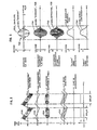
- the frequency upconversion process will be modelled in order to appreciate the importance of adequate sum frequency rejection, shown in Fig. 2.
- the descending echo spectrum 700 is mixed with a descending local oscillator frequency 702 in the neigh- borhoood of 17 MHz to produce a constant "intermediate frequency" spectrum 704 at the difference frequency of 14 MHz.
- the sum frequency spectrum 706, occurring at 19-21 MHz should be rejected from the IF amplification process. Otherwise a heterodyne in the neighborhood of 6 MHz will appear in the detector output.
- a typical single incoming RF echo signal 720 will have a 3-MHz carrier frequency and a duration of 1 microsecond.
- the video, or picture envelope information (pixel detail) is indicated by 722.
- the upconverted equivalent of 720, filtered to pass only the difference frequency is indicated as 724.
- the significance of the waveform 724 is that it contains a perfect reconstruction of the original envelope 722 and a high frequency carrier 726 of 14 MHz. Such a waveform, passing through a simple detector, can easily produce a nearly perfect video representation of the original envelope (728).
- the resulting waveform 730 produces a 6-MHz heterodyne 732, which leads to a "dirty" detection 734 comprising 6 MHz ripple content.
- the detector output 728 or 734 must be free of ripple content, at either 6 or 17 MHz, because the post-processing deconvolution has the effect of preemphasizing high-frequency ripple components in the detector output.
- there is better rejection of residual local oscillator signal This is important because presence of the local oscillator at point 676 (of Fig.
- superheterodyne receiver of this type has the advantage that signals are shifted far away from the incoming RF spectrum early in the processing: the feedback problem is minimal compared to a straight baseband RF (or TRF) receiver or even compared to a conventional downconversion superheterodyne.
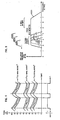
- the upconversion receiver can be adapted to operate in several distinct frequency ranges (3.5, 5, 7.5 MHz of Fig. 4) by introducing a switchable DC bias into the TSC ramp waveform. This can be accomplished by the use of an operator switch 688 that acts on generator 656 (of Fig. 1).
- the entire receiver will function with a single choice of ultrasound transducer frequency spectra, and the broad bandpass filters 648 or 654 can have their passband reduced only to cover the more limited range to minimize IM distortion.
- the choices available for the broad passband filters 648 or 654 are summarized in Fig. 5.
- the frequency response 800 for the broad bandpass filters 648 or 654 for the general case is wide enough to admit every frequency capable of being tissue signature-processed. For example, if the receiver were to function for a 3.5-MHz crystal, the passbands 802, 804, 806 would be active through the entire receiver. When the receiver is switched to the 5-MHz mode, a similar set of moving passbands becomes active in region 808. Obviously the total frequency response 800 of filters 648 and 654 need be only as broad as selectable passbands employed through the manner of programming the local oscillator. it should be noted that programming the local oscillator 658 is a much more economical way of 1TIoving the passband frequency spectra of a receiver than dynamically tuning high-pass and lowpass filter sections.
- this oscillator tuning after the preselector filter is generally permissible only because the ratio of stop- band to passband amplitudes is lower than in the case of the "strong adjacent carrier" problem in commercial (short wave) communications systems, plagued with substantial signal fading problems.
- the main source of "strong adjacent carrier" signal in ultrasound is the low-frequency component (1.6-2.3 MHz) present along with the high-frequency information spectra (3.5-4.8 MHz) of interest when imaging near echoes. Since even this strong low-frequency component rarely exceeds the amplitude of the high-frequency components, there is generally no significant problem in allowing all frequencies to slip through the preselector (648, 652, 654 of Fig. 1) and to feed the balanced modulator.
- the upconversion receiver of Fig. 1 includes a "tracking preselector" (replacing 648, 652 of Fig. 1) with tunable RF circuitry being controlled by a signal on leads 657 from the ramp generator 656.
- a narrow passband tunable preselector By combining a narrow passband tunable preselector with the full upconversion feature, one in essence obtains the maximum possible dynamic range (reducing IM distortion and noise) for a given bandwitdth (rise time merit).
Landscapes
- Engineering & Computer Science (AREA)
- Physics & Mathematics (AREA)
- Radar, Positioning & Navigation (AREA)
- Remote Sensing (AREA)
- Computer Networks & Wireless Communication (AREA)
- General Physics & Mathematics (AREA)
- Acoustics & Sound (AREA)
- Power Engineering (AREA)
- Ultra Sonic Daignosis Equipment (AREA)
- Investigating Or Analyzing Materials By The Use Of Ultrasonic Waves (AREA)
Applications Claiming Priority (2)
| Application Number | Priority Date | Filing Date | Title |
|---|---|---|---|
| US70758485A | 1985-03-04 | 1985-03-04 | |
| US707584 | 1985-03-04 |
Publications (2)
| Publication Number | Publication Date |
|---|---|
| EP0193899A1 EP0193899A1 (en) | 1986-09-10 |
| EP0193899B1 true EP0193899B1 (en) | 1990-06-13 |
Family
ID=24842285
Family Applications (1)
| Application Number | Title | Priority Date | Filing Date |
|---|---|---|---|
| EP19860102658 Expired - Lifetime EP0193899B1 (en) | 1985-03-04 | 1986-02-28 | Tissue signature tracking transceiver having upconverted if amplification |
Country Status (5)
| Country | Link |
|---|---|
| EP (1) | EP0193899B1 (ja) |
| JP (1) | JPS61253047A (ja) |
| CN (1) | CN86102114A (ja) |
| DE (1) | DE3671977D1 (ja) |
| IN (1) | IN166145B (ja) |
Cited By (25)
| Publication number | Priority date | Publication date | Assignee | Title |
|---|---|---|---|---|
| US6353735B1 (en) | 1998-10-21 | 2002-03-05 | Parkervision, Inc. | MDG method for output signal generation |
| US6370371B1 (en) | 1998-10-21 | 2002-04-09 | Parkervision, Inc. | Applications of universal frequency translation |
| US6421534B1 (en) | 1998-10-21 | 2002-07-16 | Parkervision, Inc. | Integrated frequency translation and selectivity |
| US6542722B1 (en) | 1998-10-21 | 2003-04-01 | Parkervision, Inc. | Method and system for frequency up-conversion with variety of transmitter configurations |
| US6560301B1 (en) | 1998-10-21 | 2003-05-06 | Parkervision, Inc. | Integrated frequency translation and selectivity with a variety of filter embodiments |
| US6580902B1 (en) | 1998-10-21 | 2003-06-17 | Parkervision, Inc. | Frequency translation using optimized switch structures |
| US6647250B1 (en) | 1998-10-21 | 2003-11-11 | Parkervision, Inc. | Method and system for ensuring reception of a communications signal |
| US6694128B1 (en) | 1998-08-18 | 2004-02-17 | Parkervision, Inc. | Frequency synthesizer using universal frequency translation technology |
| US6704558B1 (en) | 1999-01-22 | 2004-03-09 | Parkervision, Inc. | Image-reject down-converter and embodiments thereof, such as the family radio service |
| US6704549B1 (en) | 1999-03-03 | 2004-03-09 | Parkvision, Inc. | Multi-mode, multi-band communication system |
| US6813485B2 (en) | 1998-10-21 | 2004-11-02 | Parkervision, Inc. | Method and system for down-converting and up-converting an electromagnetic signal, and transforms for same |
| US7653145B2 (en) | 1999-08-04 | 2010-01-26 | Parkervision, Inc. | Wireless local area network (WLAN) using universal frequency translation technology including multi-phase embodiments and circuit implementations |
| US7653158B2 (en) | 2001-11-09 | 2010-01-26 | Parkervision, Inc. | Gain control in a communication channel |
| US7693230B2 (en) | 1999-04-16 | 2010-04-06 | Parkervision, Inc. | Apparatus and method of differential IQ frequency up-conversion |
| US7724845B2 (en) | 1999-04-16 | 2010-05-25 | Parkervision, Inc. | Method and system for down-converting and electromagnetic signal, and transforms for same |
| US7773688B2 (en) | 1999-04-16 | 2010-08-10 | Parkervision, Inc. | Method, system, and apparatus for balanced frequency up-conversion, including circuitry to directly couple the outputs of multiple transistors |
| US7822401B2 (en) | 2000-04-14 | 2010-10-26 | Parkervision, Inc. | Apparatus and method for down-converting electromagnetic signals by controlled charging and discharging of a capacitor |
| US7865177B2 (en) | 1998-10-21 | 2011-01-04 | Parkervision, Inc. | Method and system for down-converting an electromagnetic signal, and transforms for same, and aperture relationships |
| US7894789B2 (en) | 1999-04-16 | 2011-02-22 | Parkervision, Inc. | Down-conversion of an electromagnetic signal with feedback control |
| US7991815B2 (en) | 2000-11-14 | 2011-08-02 | Parkervision, Inc. | Methods, systems, and computer program products for parallel correlation and applications thereof |
| US8019291B2 (en) | 1998-10-21 | 2011-09-13 | Parkervision, Inc. | Method and system for frequency down-conversion and frequency up-conversion |
| US8160196B2 (en) | 2002-07-18 | 2012-04-17 | Parkervision, Inc. | Networking methods and systems |
| US8233855B2 (en) | 1998-10-21 | 2012-07-31 | Parkervision, Inc. | Up-conversion based on gated information signal |
| US8295406B1 (en) | 1999-08-04 | 2012-10-23 | Parkervision, Inc. | Universal platform module for a plurality of communication protocols |
| US8407061B2 (en) | 2002-07-18 | 2013-03-26 | Parkervision, Inc. | Networking methods and systems |
Families Citing this family (5)
| Publication number | Priority date | Publication date | Assignee | Title |
|---|---|---|---|---|
| JPS63277045A (ja) * | 1987-03-11 | 1988-11-15 | Tokyo Keiki Co Ltd | 超音波医用診断装置 |
| US6827686B2 (en) * | 2002-08-21 | 2004-12-07 | Koninklijke Philips Electronics N.V. | System and method for improved harmonic imaging |
| JP5735496B2 (ja) * | 2010-06-04 | 2015-06-17 | 株式会社日立メディコ | 超音波診断装置 |
| CN105278438B (zh) * | 2014-06-24 | 2018-04-24 | 上海梅山钢铁股份有限公司 | 一种焦炉机车数据射频传送和监控的方法及监测器电路 |
| CN106338710A (zh) * | 2015-07-07 | 2017-01-18 | 天津市远卓自动化设备制造有限公司 | 一种提高船只航行安全防船只碰撞的方法 |
Family Cites Families (4)
| Publication number | Priority date | Publication date | Assignee | Title |
|---|---|---|---|---|
| JPS5823978B2 (ja) * | 1975-11-11 | 1983-05-18 | ソニー株式会社 | チユ−ナ |
| DE2724437B1 (de) * | 1977-05-31 | 1978-06-15 | Siemens Ag | Nach dem Impuls-Echo-Verfahren arbeitendes Ultraschall-Bildgeraet |
| US4352210A (en) * | 1980-09-12 | 1982-09-28 | General Electric Company | Linear mixer with reduced spurious responses |
| US4442715A (en) * | 1980-10-23 | 1984-04-17 | General Electric Company | Variable frequency ultrasonic system |
-
1986
- 1986-02-28 EP EP19860102658 patent/EP0193899B1/en not_active Expired - Lifetime
- 1986-02-28 DE DE8686102658T patent/DE3671977D1/de not_active Expired - Lifetime
- 1986-02-28 IN IN177/DEL/86A patent/IN166145B/en unknown
- 1986-03-04 CN CN198686102114A patent/CN86102114A/zh active Pending
- 1986-03-04 JP JP61047153A patent/JPS61253047A/ja active Pending
Cited By (45)
| Publication number | Priority date | Publication date | Assignee | Title |
|---|---|---|---|---|
| US6694128B1 (en) | 1998-08-18 | 2004-02-17 | Parkervision, Inc. | Frequency synthesizer using universal frequency translation technology |
| US7826817B2 (en) | 1998-10-21 | 2010-11-02 | Parker Vision, Inc. | Applications of universal frequency translation |
| US6560301B1 (en) | 1998-10-21 | 2003-05-06 | Parkervision, Inc. | Integrated frequency translation and selectivity with a variety of filter embodiments |
| US6542722B1 (en) | 1998-10-21 | 2003-04-01 | Parkervision, Inc. | Method and system for frequency up-conversion with variety of transmitter configurations |
| US6353735B1 (en) | 1998-10-21 | 2002-03-05 | Parkervision, Inc. | MDG method for output signal generation |
| US6580902B1 (en) | 1998-10-21 | 2003-06-17 | Parkervision, Inc. | Frequency translation using optimized switch structures |
| US6647250B1 (en) | 1998-10-21 | 2003-11-11 | Parkervision, Inc. | Method and system for ensuring reception of a communications signal |
| US6687493B1 (en) | 1998-10-21 | 2004-02-03 | Parkervision, Inc. | Method and circuit for down-converting a signal using a complementary FET structure for improved dynamic range |
| US6370371B1 (en) | 1998-10-21 | 2002-04-09 | Parkervision, Inc. | Applications of universal frequency translation |
| US8340618B2 (en) | 1998-10-21 | 2012-12-25 | Parkervision, Inc. | Method and system for down-converting an electromagnetic signal, and transforms for same, and aperture relationships |
| US8233855B2 (en) | 1998-10-21 | 2012-07-31 | Parkervision, Inc. | Up-conversion based on gated information signal |
| US8190116B2 (en) | 1998-10-21 | 2012-05-29 | Parker Vision, Inc. | Methods and systems for down-converting a signal using a complementary transistor structure |
| US6813485B2 (en) | 1998-10-21 | 2004-11-02 | Parkervision, Inc. | Method and system for down-converting and up-converting an electromagnetic signal, and transforms for same |
| US7865177B2 (en) | 1998-10-21 | 2011-01-04 | Parkervision, Inc. | Method and system for down-converting an electromagnetic signal, and transforms for same, and aperture relationships |
| US8160534B2 (en) | 1998-10-21 | 2012-04-17 | Parkervision, Inc. | Applications of universal frequency translation |
| US8019291B2 (en) | 1998-10-21 | 2011-09-13 | Parkervision, Inc. | Method and system for frequency down-conversion and frequency up-conversion |
| US7936022B2 (en) | 1998-10-21 | 2011-05-03 | Parkervision, Inc. | Method and circuit for down-converting a signal |
| US7693502B2 (en) | 1998-10-21 | 2010-04-06 | Parkervision, Inc. | Method and system for down-converting an electromagnetic signal, transforms for same, and aperture relationships |
| US7697916B2 (en) | 1998-10-21 | 2010-04-13 | Parkervision, Inc. | Applications of universal frequency translation |
| US7937059B2 (en) | 1998-10-21 | 2011-05-03 | Parkervision, Inc. | Converting an electromagnetic signal via sub-sampling |
| US6836650B2 (en) | 1998-10-21 | 2004-12-28 | Parkervision, Inc. | Methods and systems for down-converting electromagnetic signals, and applications thereof |
| US6798351B1 (en) | 1998-10-21 | 2004-09-28 | Parkervision, Inc. | Automated meter reader applications of universal frequency translation |
| US6421534B1 (en) | 1998-10-21 | 2002-07-16 | Parkervision, Inc. | Integrated frequency translation and selectivity |
| US6704558B1 (en) | 1999-01-22 | 2004-03-09 | Parkervision, Inc. | Image-reject down-converter and embodiments thereof, such as the family radio service |
| US6704549B1 (en) | 1999-03-03 | 2004-03-09 | Parkvision, Inc. | Multi-mode, multi-band communication system |
| US8594228B2 (en) | 1999-04-16 | 2013-11-26 | Parkervision, Inc. | Apparatus and method of differential IQ frequency up-conversion |
| US8077797B2 (en) | 1999-04-16 | 2011-12-13 | Parkervision, Inc. | Method, system, and apparatus for balanced frequency up-conversion of a baseband signal |
| US7693230B2 (en) | 1999-04-16 | 2010-04-06 | Parkervision, Inc. | Apparatus and method of differential IQ frequency up-conversion |
| US7929638B2 (en) | 1999-04-16 | 2011-04-19 | Parkervision, Inc. | Wireless local area network (WLAN) using universal frequency translation technology including multi-phase embodiments |
| US8229023B2 (en) | 1999-04-16 | 2012-07-24 | Parkervision, Inc. | Wireless local area network (WLAN) using universal frequency translation technology including multi-phase embodiments |
| US8036304B2 (en) | 1999-04-16 | 2011-10-11 | Parkervision, Inc. | Apparatus and method of differential IQ frequency up-conversion |
| US8224281B2 (en) | 1999-04-16 | 2012-07-17 | Parkervision, Inc. | Down-conversion of an electromagnetic signal with feedback control |
| US7894789B2 (en) | 1999-04-16 | 2011-02-22 | Parkervision, Inc. | Down-conversion of an electromagnetic signal with feedback control |
| US7773688B2 (en) | 1999-04-16 | 2010-08-10 | Parkervision, Inc. | Method, system, and apparatus for balanced frequency up-conversion, including circuitry to directly couple the outputs of multiple transistors |
| US7724845B2 (en) | 1999-04-16 | 2010-05-25 | Parkervision, Inc. | Method and system for down-converting and electromagnetic signal, and transforms for same |
| US8223898B2 (en) | 1999-04-16 | 2012-07-17 | Parkervision, Inc. | Method and system for down-converting an electromagnetic signal, and transforms for same |
| US8295406B1 (en) | 1999-08-04 | 2012-10-23 | Parkervision, Inc. | Universal platform module for a plurality of communication protocols |
| US7653145B2 (en) | 1999-08-04 | 2010-01-26 | Parkervision, Inc. | Wireless local area network (WLAN) using universal frequency translation technology including multi-phase embodiments and circuit implementations |
| US7822401B2 (en) | 2000-04-14 | 2010-10-26 | Parkervision, Inc. | Apparatus and method for down-converting electromagnetic signals by controlled charging and discharging of a capacitor |
| US8295800B2 (en) | 2000-04-14 | 2012-10-23 | Parkervision, Inc. | Apparatus and method for down-converting electromagnetic signals by controlled charging and discharging of a capacitor |
| US7991815B2 (en) | 2000-11-14 | 2011-08-02 | Parkervision, Inc. | Methods, systems, and computer program products for parallel correlation and applications thereof |
| US7653158B2 (en) | 2001-11-09 | 2010-01-26 | Parkervision, Inc. | Gain control in a communication channel |
| US8446994B2 (en) | 2001-11-09 | 2013-05-21 | Parkervision, Inc. | Gain control in a communication channel |
| US8407061B2 (en) | 2002-07-18 | 2013-03-26 | Parkervision, Inc. | Networking methods and systems |
| US8160196B2 (en) | 2002-07-18 | 2012-04-17 | Parkervision, Inc. | Networking methods and systems |
Also Published As
| Publication number | Publication date |
|---|---|
| EP0193899A1 (en) | 1986-09-10 |
| DE3671977D1 (de) | 1990-07-19 |
| IN166145B (ja) | 1990-03-17 |
| JPS61253047A (ja) | 1986-11-10 |
| CN86102114A (zh) | 1987-04-01 |
Similar Documents
| Publication | Publication Date | Title |
|---|---|---|
| EP0193899B1 (en) | Tissue signature tracking transceiver having upconverted if amplification | |
| US4676105A (en) | Tissue signature tracking transceiver | |
| US5394750A (en) | Tissue signature tracking transceiver | |
| US5363104A (en) | Jamming signal cancellation system | |
| DE19882575B3 (de) | Ultraschallbilderzeugung unter Verwendung der Fundamentalfrequenz | |
| EP0140392B1 (en) | Ultrasonic imaging apparatus | |
| US20060089115A1 (en) | Dual band superheterodyne receiver | |
| DE3735121A1 (de) | Impulskompressionsvorrichtung fuer ultraschallabbildungsverfahren | |
| US5187687A (en) | Production of images | |
| US20070037546A1 (en) | Superheterodyne receiver having at least one downconversion stage empolying a single image reject filter stage and both low-side injection and high-side injection of a local oscillator signal | |
| US4691571A (en) | Tissue signature tracking transceiver having upconverted IF amplification | |
| US4181892A (en) | Sweeping noise blanker | |
| US4267600A (en) | Modulation monitoring apparatus | |
| US5396655A (en) | Adaptive canceler for contiguous band filtering | |
| EP0345346B1 (en) | Chirped backscatter filter | |
| JP2760611B2 (ja) | 超音波診断装置 | |
| EP0206290B1 (de) | Verfahren und Vorrichtung zur Erzeugung von Abbildungen | |
| JPS60222040A (ja) | 連続超音波ドツプラ装置 | |
| JPH05176923A (ja) | 超音波診断装置 | |
| JPH0423227B2 (ja) | ||
| JPS6322522Y2 (ja) | ||
| Sullivan | Microwave Homodyne Receivers | |
| CA2521376A1 (en) | Dual band superheterodyne radar receiver | |
| JPS60116341A (ja) | 超音波診断装置 | |
| JPH0421376B2 (ja) |
Legal Events
| Date | Code | Title | Description |
|---|---|---|---|
| PUAI | Public reference made under article 153(3) epc to a published international application that has entered the european phase |
Free format text: ORIGINAL CODE: 0009012 |
|
| AK | Designated contracting states |
Kind code of ref document: A1 Designated state(s): DE FR GB IT NL SE |
|
| 17P | Request for examination filed |
Effective date: 19870213 |
|
| 17Q | First examination report despatched |
Effective date: 19880318 |
|
| GRAA | (expected) grant |
Free format text: ORIGINAL CODE: 0009210 |
|
| AK | Designated contracting states |
Kind code of ref document: B1 Designated state(s): DE FR GB IT NL SE |
|
| PG25 | Lapsed in a contracting state [announced via postgrant information from national office to epo] |
Ref country code: IT Free format text: LAPSE BECAUSE OF FAILURE TO SUBMIT A TRANSLATION OF THE DESCRIPTION OR TO PAY THE FEE WITHIN THE PRE;WARNING: LAPSES OF ITALIAN PATENTS WITH EFFECTIVE DATE BEFORE 2007 MAY HAVE OCCURRED AT ANY TIME BEFORE 2007. THE CORRECT EFFECTIVE DATE MAY BE DIFFERENT FROM THE ONE RECORDED.SCRIBED TIME-LIMIT Effective date: 19900613 Ref country code: SE Effective date: 19900613 Ref country code: FR Effective date: 19900613 Ref country code: NL Effective date: 19900613 |
|
| REF | Corresponds to: |
Ref document number: 3671977 Country of ref document: DE Date of ref document: 19900719 |
|
| EN | Fr: translation not filed | ||
| NLV1 | Nl: lapsed or annulled due to failure to fulfill the requirements of art. 29p and 29m of the patents act | ||
| PGFP | Annual fee paid to national office [announced via postgrant information from national office to epo] |
Ref country code: GB Payment date: 19901227 Year of fee payment: 6 |
|
| PLBE | No opposition filed within time limit |
Free format text: ORIGINAL CODE: 0009261 |
|
| STAA | Information on the status of an ep patent application or granted ep patent |
Free format text: STATUS: NO OPPOSITION FILED WITHIN TIME LIMIT |
|
| 26N | No opposition filed | ||
| PG25 | Lapsed in a contracting state [announced via postgrant information from national office to epo] |
Ref country code: DE Effective date: 19911101 |
|
| PG25 | Lapsed in a contracting state [announced via postgrant information from national office to epo] |
Ref country code: GB Effective date: 19920228 |
|
| GBPC | Gb: european patent ceased through non-payment of renewal fee |