EP0193847A1 - Vehicle rear suspension system - Google Patents
Vehicle rear suspension system Download PDFInfo
- Publication number
- EP0193847A1 EP0193847A1 EP86102440A EP86102440A EP0193847A1 EP 0193847 A1 EP0193847 A1 EP 0193847A1 EP 86102440 A EP86102440 A EP 86102440A EP 86102440 A EP86102440 A EP 86102440A EP 0193847 A1 EP0193847 A1 EP 0193847A1
- Authority
- EP
- European Patent Office
- Prior art keywords
- swing arm
- lateral
- vehicle body
- longitudinal member
- suspension system
- Prior art date
- Legal status (The legal status is an assumption and is not a legal conclusion. Google has not performed a legal analysis and makes no representation as to the accuracy of the status listed.)
- Granted
Links
Images


Classifications
-
- B—PERFORMING OPERATIONS; TRANSPORTING
- B60—VEHICLES IN GENERAL
- B60G—VEHICLE SUSPENSION ARRANGEMENTS
- B60G99/00—Subject matter not provided for in other groups of this subclass
-
- B—PERFORMING OPERATIONS; TRANSPORTING
- B60—VEHICLES IN GENERAL
- B60G—VEHICLE SUSPENSION ARRANGEMENTS
- B60G3/00—Resilient suspensions for a single wheel
- B60G3/18—Resilient suspensions for a single wheel with two or more pivoted arms, e.g. parallelogram
- B60G3/20—Resilient suspensions for a single wheel with two or more pivoted arms, e.g. parallelogram all arms being rigid
- B60G3/22—Resilient suspensions for a single wheel with two or more pivoted arms, e.g. parallelogram all arms being rigid a rigid arm forming the axle housing
-
- B—PERFORMING OPERATIONS; TRANSPORTING
- B60—VEHICLES IN GENERAL
- B60G—VEHICLE SUSPENSION ARRANGEMENTS
- B60G3/00—Resilient suspensions for a single wheel
- B60G3/18—Resilient suspensions for a single wheel with two or more pivoted arms, e.g. parallelogram
- B60G3/28—Resilient suspensions for a single wheel with two or more pivoted arms, e.g. parallelogram at least one of the arms itself being resilient, e.g. leaf spring
- B60G3/285—Resilient suspensions for a single wheel with two or more pivoted arms, e.g. parallelogram at least one of the arms itself being resilient, e.g. leaf spring the arm being essentially parallel to the longitudinal axis of the vehicle
-
- B—PERFORMING OPERATIONS; TRANSPORTING
- B60—VEHICLES IN GENERAL
- B60G—VEHICLE SUSPENSION ARRANGEMENTS
- B60G7/00—Pivoted suspension arms; Accessories thereof
- B60G7/02—Attaching arms to sprung part of vehicle
-
- B—PERFORMING OPERATIONS; TRANSPORTING
- B60—VEHICLES IN GENERAL
- B60G—VEHICLE SUSPENSION ARRANGEMENTS
- B60G99/00—Subject matter not provided for in other groups of this subclass
- B60G99/004—Other suspension arrangements with rubber springs
-
- B—PERFORMING OPERATIONS; TRANSPORTING
- B60—VEHICLES IN GENERAL
- B60G—VEHICLE SUSPENSION ARRANGEMENTS
- B60G2200/00—Indexing codes relating to suspension types
- B60G2200/10—Independent suspensions
- B60G2200/13—Independent suspensions with longitudinal arms only
- B60G2200/132—Independent suspensions with longitudinal arms only with a single trailing arm
- B60G2200/1324—Independent suspensions with longitudinal arms only with a single trailing arm with a resilient trailing arm
-
- B—PERFORMING OPERATIONS; TRANSPORTING
- B60—VEHICLES IN GENERAL
- B60G—VEHICLE SUSPENSION ARRANGEMENTS
- B60G2200/00—Indexing codes relating to suspension types
- B60G2200/10—Independent suspensions
- B60G2200/18—Multilink suspensions, e.g. elastokinematic arrangements
-
- B—PERFORMING OPERATIONS; TRANSPORTING
- B60—VEHICLES IN GENERAL
- B60G—VEHICLE SUSPENSION ARRANGEMENTS
- B60G2200/00—Indexing codes relating to suspension types
- B60G2200/10—Independent suspensions
- B60G2200/18—Multilink suspensions, e.g. elastokinematic arrangements
- B60G2200/182—Multilink suspensions, e.g. elastokinematic arrangements with one longitudinal arm or rod and lateral rods
-
- B—PERFORMING OPERATIONS; TRANSPORTING
- B60—VEHICLES IN GENERAL
- B60G—VEHICLE SUSPENSION ARRANGEMENTS
- B60G2202/00—Indexing codes relating to the type of spring, damper or actuator
- B60G2202/30—Spring/Damper and/or actuator Units
- B60G2202/31—Spring/Damper and/or actuator Units with the spring arranged around the damper, e.g. MacPherson strut
- B60G2202/312—The spring being a wound spring
-
- B—PERFORMING OPERATIONS; TRANSPORTING
- B60—VEHICLES IN GENERAL
- B60G—VEHICLE SUSPENSION ARRANGEMENTS
- B60G2204/00—Indexing codes related to suspensions per se or to auxiliary parts
- B60G2204/10—Mounting of suspension elements
- B60G2204/14—Mounting of suspension arms
- B60G2204/147—Mounting of suspension arms on the vehicle engine body
-
- B—PERFORMING OPERATIONS; TRANSPORTING
- B60—VEHICLES IN GENERAL
- B60G—VEHICLE SUSPENSION ARRANGEMENTS
- B60G2204/00—Indexing codes related to suspensions per se or to auxiliary parts
- B60G2204/10—Mounting of suspension elements
- B60G2204/15—Mounting of subframes
-
- B—PERFORMING OPERATIONS; TRANSPORTING
- B60—VEHICLES IN GENERAL
- B60G—VEHICLE SUSPENSION ARRANGEMENTS
- B60G2204/00—Indexing codes related to suspensions per se or to auxiliary parts
- B60G2204/40—Auxiliary suspension parts; Adjustment of suspensions
- B60G2204/41—Elastic mounts, e.g. bushings
-
- B—PERFORMING OPERATIONS; TRANSPORTING
- B60—VEHICLES IN GENERAL
- B60G—VEHICLE SUSPENSION ARRANGEMENTS
- B60G2204/00—Indexing codes related to suspensions per se or to auxiliary parts
- B60G2204/40—Auxiliary suspension parts; Adjustment of suspensions
- B60G2204/44—Centering or positioning means
- B60G2204/4404—Retainers for holding a fixing element, e.g. bushing, nut, bolt etc., until it is tightly fixed in position
Definitions
- the present invention relates to a vehicle suspension system and more particularly to a rear suspension system of a motor vehicle.
- Conventional independent type vehicle rear suspension systems include a so-called trailing arm type and a semi- trailing arm type.
- These types of suspension systems include a trailing arm extending in a longitudinal direction of the vehicle body and having a front end attached to the vehicle body for vertical swinging movements, the trailing arm being secured at the rear end to a hub carrier which carries a rear wheel hub.
- a substantially vertically extending damping strut is provided between the rear end portion of the trailing arm and the vehicle body.
- the suspension systems of these types are advantageous in that they are simple in structure so that the overall weight can be decreased.
- the suspension systems of these types require trailing arm of substantial cross-sectional area in order to ensure an adequate lateral rigidity.
- the front end of the trailing arm must be attached to the vehicle body at laterally spaced positions. As the results, the trailing arm must be of a substantial dimension and therefore of an increased weight
- Japanese laid-open utirrty model 56-62205 proposes, in a vehicle rear suspension system including a trailing arm having a front end mounted on a vehicle body for vertical swinging movements and a rear end carrying a wheel hub, to provide a pair of vertically spaced lateral links which are pivotabty connected at the laterally outward ends to the rear end portions of the trailing arm and at the laterally inward ends to the vehicle body.
- This type of suspension system is advantageous in that the lateral links supports the trailing arm in the lateral direction so that the trailing arm may not be required to possess by itself a substantial lateral rigidity.
- a vehicle rear suspension system which includes a substantially ton- gitudinally extending swing arm having one end pivotably connected with the vehicle body for vertical swinging movements and the other end connected with the wheel hub carrier, and three lateral links extending in substantially lateral directions.
- the lateral links are pivotably connected at one ends with the vehicle body and at the other ends with the wheel hub carrier at locations which are not aligned on a single straight line.
- the three lateral links function to determine the position of the wheel.
- the swing arm is preferably of a structure having a small rigidity in lateral direction.
- the swing arm may have a very small lateral thickness with a relatively large heigthwise dimension so that it can be easily deflected in the lateral direction.
- the swing arm may be attached to the vehicle body through resilient means such as a rubber bush. It should however be noted that even though the swing arm is constructed to have a small rigidity in lateral directions and mounted on the vehicle body through a resilient rubber bush, the swing arm can still cause a restriction against the swinging movements of the lateral links due to the geometrical arrangements.
- the wheel hub carrier Since the swing arm conducts swinging movements about the axis of pivotably attachment with the vehicle body, the wheel hub carrier is moved along an arcuate path having the center of arc at the axis of the pivotable ' attachment in response to the swinging movements of the swing arm.
- the lateral links are required to have freedoms not only for vertical swinging movements but also for certain fore-and-aft swinging movements. It should however be noted that it is not easy to obtain a structure which can permit such movements of the lateral links.
- Another object of the present invention is to provide a vehicle rear suspension system having a substantially longitudinally extending swing arm and three substantially laterally extending links, in which fore-and-aft swinging movements of the lateral links can be minimized.
- Still further object of the present invention is to provide a vehicle rear suspension system in which deformations of the resilient means for mounting the lateral links to the vehicle body can be significantly decreased and therefore the durability of the resilient means can be increased.
- the present invention provides a vehicle rear suspension system comprising swing arm means extending substantially longitudinally and having one end connected to a vehicle body for vertical swinging movements substantially about a center of movement, said one end of the swing arm means being resiliently connected to the vehicle body, wheel carrying means for carrying a rear wheel for rotation about a rotation axis, said wheel carrying means being connected rigidly with said swing arm means at the other end of the swing arm means so that a longitudinal force and a rotating force about a transverse axis extending in a lateral direction of the vehicle body can be transmitted between the swing arm means and the wheel carrying means, first, second and third lateral links extending in substantially lateral direction of the vehicle body, each of said lateral links having one end pivotably connected through a single pivot means with said wheel carrying means and the other end pivotably
- a sub-frame which has a substantially longitudinally extending section which is attached to the vehicle body at front and rear end portions, the rear end portion being located higher than the front end portion, said one end of the swing arm means being attached to the sub-frame at a heightwise position between the front and rear end portions of the longitudinally extending section of the sub-frame.
- the swing arm means is attached to the vehicle body through resilient bush means which is mounted on the vehicle body such that an axial sliding movement of the bush means is permitted.
- a vehicle rear suspension system 14 for connecting a rear wheel 10 rotatably carried by a wheel carrier 12 with a vehicle body 16 .
- the suspension system 14 includes a substantially longitudinally extending swing arm 18, a first lateral link 20, a second lateral link 22 and a third lateral link 24.
- the swing arm 18 is constituted by a plate member having a substantial heightwise dimension and a relatively small thickness.
- the vehicle body 16 includes a sub-frame 28 which has a substantially longitudinally extending section 30 and a pair of cross-members 36 and 38 which connects the longitudinal section 30 to the corresponding longitudinal section 30 at the other side of the vehicle body 16.
- the section 30 of the sub-frame 28 has a front end portion 30a and a rear end portion 30b mounted on the vehicle body 16 respectively through rubber mounts 30c and 30d.
- the swing arm 18 is attached at the front end portion 18a through a rubber bush 34 and a mounting bolt 32 to the section 30 of the sub-frame 28 for swingable movement about the axis of the bolt 32.
- the rubber bush 34 may be of a structure as shown in Figure 7 and include an outer tube 34a secured to the front end portion 18a of the swing arm 18, an inner tube 34b and a cylindrical rubber member 34c attached at the outer and inner peripheries to the outer tube 34a and the inner tube 34b, respectively.
- the longitudinal section 30 of the sub-frame 28 is curved upward from the front end portion 30a toward the rear end portion 30b so that the rear end portion 30b is mounted on the vehicle body 16 at a position higher than the position where the front end portion 30a is mounted on the vehicle body 1 6.
- the section 30 is provided with a bracket 30e which projects upward from the upper surface of the section 30.
- the bracket 30e has a pair of mounting flanges 30f.
- the rubber bush 34 has a spacer tube 34d on which the inner tube 34b is axially slidably mounted.
- the spacer tube 34d is placed between the mounting flanges 30f and the mounting bolt 32 is inserted through the flanges 30f and the spacer tube 34d.
- the swing arm 18 is securely connected at the rear end portion 18b to the wheel carrier 12. It will be understood that, with this arrangement, the front end portion 18a of the swing arm 18 is attached to the sub-frame 28 at a heightwise position between the front end portion 30a and the rear end portion 30b of the section 30 so that the longitudinal load transmitted through the swing arm 18 is shared by the rubber mounts 30c and 30d.
- the lateral links 20, 22 and 24 extend substantially laterally with respect to the vehicle body 16.
- the lateral links 20, 22 and 2 4 have laterally outer ends 20a, 22a and 24a, respectively, which are connected with the wheel carrier 12 at spaced apart positions by means of ball joints 21.
- the positions of connections of the outer ends 20a, 22a and 24a to the wheel carrier 12 are such that lateral projections of these positions on a longitudinally vertical plane are not aligned on a straight line.
- the lateral links 20, 22 and 24 further have laterally inner ends 20b, 22b and 24b, respectively, which are attached to the longitudinal section 30 of the sub-frame 28 by means of rubber bushes 20c, 22c and 24c.
- Figure 3 shows one example of the rubber bush 22c.
- the bush 22c includes an outer tube 23a secured to the lateral link 22, and inner tube 23b and a cylindrical rubber member 23c secured at the outer and inner peripheral surfaces to the outer tube 23a and the inner tube 23b, respectively.
- the sub-frame section 30 is provided with a mounting bracket 30g having a pair of mounting flanges 30h.
- the inner tube 23b of the rubber bush 22c is held between the flanges 30h of the mounting bracket 30g and a mounting bolt 25 is inserted through the flanges 30h and the inner tube 23b.
- the rubber bushes 20c and 24c for the other lateral links 22 and 24 have similar structures.
- the rubber bush 22c for the lateral link 22 is arranged such that its axis as defined by the axis of the mounting bolt 25 is directed in a projection to a longitudinally vertical plane toward the center 18c of the swinging movement of the swing arm 18 as shown by a line 22d.
- the projections of the axes of the rubber bushes 20c and 24c are also directed toward the center 18c of swinging movement of the swing arm 18 as shown by lines 20d and 24d, respectively.
- the axes of the rubber bushes 20c, 22c and 24c are directed as shown by arrows 20e, 22e and 24e in Figure 1.
- the suspension system 14 further includes shock absorber 26 which extends substantially vertically.
- the shock absorber 26 may be of a known structure including a damping strut and a coil spring.
- the shock absorber 26 has a lower end attached to the wheel carrier 12 for swinging movement about a laterally extending horizontal axis and an upper end pivotably attached to the vehicle body.
- the lateral lines 20, 22 and 24 can swing very smoothly in the directions shown by arrows 20f, 22f and 24f. Further, the directions shown by the arrows 20f, 22f and 24f are substantially in conformity with the direction of the swinging movement of the swing arm 18. It will therefore be understood that the lateral links 20, 22 and 2 4 can swing about the axes of the rubber bushes 20c, 22c and 24c without receiving substantial constraint from the swing arm 18. It is therefore possible to prevent undesirable deformations of the rubber bushes.
- the sub-frame 28 includes cross-members 36 and 38 connecting together the longitudinal sections 30.
- the cross-member 38 comprises an upper panel 38a and a lower panel 38b which are welded together at their peripheries to form a structure of closed cross-section.
- the upper panel 38a is welded to the upper surface of the longitudinal section 30.
- the lower panel 38b has a . downwardly bulged extension 38c which is located beneath the section 30 and welded to the lower side of the longitudinal section 30.
- a mounting bracket 40 for mounting the inner end portion 20b of the lateral link 20.
- the braket 40 has an upper flange 40a which is welded to the lower side of the section 30, a front flange 40b welded to a rear side wall 38d of the extension 38c in the cross-member 38 and a lower flange 40c welded to the lower side of the extension 38c.
- the rubber bush 20c for mounting the lateral link 20 is placed in the bracket 40 as shown in Figure 6.
- the bracket 40 has a bolt hole 42 and the rear side wall 38d of the cross-member 38 is formed with a bolt hole 44 which is aligned with the bolt hole 42.
- a bolt (not shown) for mounting the rubber bush 20c is passed through the bolt holes 42 and 44. This arrangement provides a rigid structure for supporting the rubber bush 20c.
Landscapes
- Engineering & Computer Science (AREA)
- Mechanical Engineering (AREA)
- Vehicle Body Suspensions (AREA)
Abstract
Description
- The present invention relates to a vehicle suspension system and more particularly to a rear suspension system of a motor vehicle.
- Conventional independent type vehicle rear suspension systems include a so-called trailing arm type and a semi- trailing arm type. These types of suspension systems include a trailing arm extending in a longitudinal direction of the vehicle body and having a front end attached to the vehicle body for vertical swinging movements, the trailing arm being secured at the rear end to a hub carrier which carries a rear wheel hub. A substantially vertically extending damping strut is provided between the rear end portion of the trailing arm and the vehicle body. The suspension systems of these types are advantageous in that they are simple in structure so that the overall weight can be decreased. There has however been recognized that the suspension systems of these types require trailing arm of substantial cross-sectional area in order to ensure an adequate lateral rigidity. Further, the front end of the trailing arm must be attached to the vehicle body at laterally spaced positions. As the results, the trailing arm must be of a substantial dimension and therefore of an increased weight
- In order to solve the above problems, Japanese laid-open utirrty model 56-62205 proposes, in a vehicle rear suspension system including a trailing arm having a front end mounted on a vehicle body for vertical swinging movements and a rear end carrying a wheel hub, to provide a pair of vertically spaced lateral links which are pivotabty connected at the laterally outward ends to the rear end portions of the trailing arm and at the laterally inward ends to the vehicle body. This type of suspension system is advantageous in that the lateral links supports the trailing arm in the lateral direction so that the trailing arm may not be required to possess by itself a substantial lateral rigidity. It should however be noted that in this arrangement there are produced toe-out movements in the wheel when the wheel is bumped upwards with respect to the vehicle body and when the wheel is rebounced downwards with respect to the vehicle body. Such toe-out movements cause a tendency of over-steer in a curved path so that there will be a danger of steering instability.
- In the Japanese laid-open patent application 60-53408 published on March 27, 1985 and corresponding to the U.S. application serial 646,070, there is proposed a vehicle rear suspension system which includes a substantially ton- gitudinally extending swing arm having one end pivotably connected with the vehicle body for vertical swinging movements and the other end connected with the wheel hub carrier, and three lateral links extending in substantially lateral directions. The lateral links are pivotably connected at one ends with the vehicle body and at the other ends with the wheel hub carrier at locations which are not aligned on a single straight line. According to the proposed, the three lateral links function to determine the position of the wheel. Therefore, it is possible to prevent or suppress the toe-out displacements in the hump and rebouncing movements of the wheel by properly determining the positions, the lengths and the orientations of the laterial links- It is also possible to control the camber angle of the wheel in a desirable manner.
- In the proposed structure, it is advisable to make the swing arm such that it does not disturb the movements of the lateral links. Thus, the swing arm is preferably of a structure having a small rigidity in lateral direction. For example, it may have a very small lateral thickness with a relatively large heigthwise dimension so that it can be easily deflected in the lateral direction. Alternatively or furthermore, the swing arm may be attached to the vehicle body through resilient means such as a rubber bush. It should however be noted that even though the swing arm is constructed to have a small rigidity in lateral directions and mounted on the vehicle body through a resilient rubber bush, the swing arm can still cause a restriction against the swinging movements of the lateral links due to the geometrical arrangements. Since the swing arm conducts swinging movements about the axis of pivotably attachment with the vehicle body, the wheel hub carrier is moved along an arcuate path having the center of arc at the axis of the pivotable 'attachment in response to the swinging movements of the swing arm. Thus, the lateral links are required to have freedoms not only for vertical swinging movements but also for certain fore-and-aft swinging movements. It should however be noted that it is not easy to obtain a structure which can permit such movements of the lateral links.
- Conventional measures for solving the problems are to mount the laterally inner ends of the lateral links through rubber bushes which can allow the fore-and-aft swinging movements of the lateral links. However, such structure is not satisfactory in that the rubber bushes are subjected to substantial torsional and compressive loads which cause complicated deformations of the rubber bushes. As the results, swinging movements of the lateral links are disturbed and the durability of the rubber bushes is adversely affected.
- It is therefore an object of the present invention to provide a vehicle rear suspension system having a substantially longitudinally extending swing arm and three substantially laterally extending links, in which smooth swinging movements of the lateral links can be ensured.
- Another object of the present invention is to provide a vehicle rear suspension system having a substantially longitudinally extending swing arm and three substantially laterally extending links, in which fore-and-aft swinging movements of the lateral links can be minimized.
- Still further object of the present invention is to provide a vehicle rear suspension system in which deformations of the resilient means for mounting the lateral links to the vehicle body can be significantly decreased and therefore the durability of the resilient means can be increased.
- According to the present invention, the above and other objects can be accomplished by mounting the three lateral links for vertical swinging movements about swinging axes which are directed in projections on a longitudinally vertical plane toward the center of the swinging movement of the swing arm- Thus, the present invention provides a vehicle rear suspension system comprising swing arm means extending substantially longitudinally and having one end connected to a vehicle body for vertical swinging movements substantially about a center of movement, said one end of the swing arm means being resiliently connected to the vehicle body, wheel carrying means for carrying a rear wheel for rotation about a rotation axis, said wheel carrying means being connected rigidly with said swing arm means at the other end of the swing arm means so that a longitudinal force and a rotating force about a transverse axis extending in a lateral direction of the vehicle body can be transmitted between the swing arm means and the wheel carrying means, first, second and third lateral links extending in substantially lateral direction of the vehicle body, each of said lateral links having one end pivotably connected through a single pivot means with said wheel carrying means and the other end pivotably connected through a single pivot means having a pivot axis with the vehicle body, said one ends of the first, second and third lateral links being connected to said wheel carrying means at locations which are not aligned on a single straight line, characterized by the fact that, in a projection to a longitudinally vertical plane, the pivot axis of the pivot means for connecting each of said lateral links to said vehicle body is directed toward the center of the movement of the swing arm means.
- According to a preferable aspect of the present invention, there is provided a sub-frame which has a substantially longitudinally extending section which is attached to the vehicle body at front and rear end portions, the rear end portion being located higher than the front end portion, said one end of the swing arm means being attached to the sub-frame at a heightwise position between the front and rear end portions of the longitudinally extending section of the sub-frame. This arrangement is advantageous in that the longitudinal load transmitted through the swing arm is shared by the front and rear end portions of the sub-frame section so that it is possible to avoid concentration of the longitudinal load to one of the end portions of the sub-frame section.
- According to a further aspect of the present invention, the swing arm means is attached to the vehicle body through resilient bush means which is mounted on the vehicle body such that an axial sliding movement of the bush means is permitted.
- The above and other objects and features of the present invention will become apparent from the following descriptions of preferred embodiments taking reference to the accompanying drawings.
-
- Figure 1 is a top plan view of a vehicle rear suspension system in accordance with one embodiment of the present invention;
- Figure 2 is a side view of the suspension system shown in Figure 1;
- Figure 3 is a sectional view of a rubber bush for mounting the lateral link on the vehicle body;
- Figure 4 is a top plan view of the suspension system shown in Figure 3;
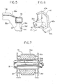
- Figure 5 is a sectional view taken along the line V-V in Figure 4;
- Figure 6 is a perspective view of a bracket used in the suspension system shown in Figures 3 and 4; and
- Figure 7 is a sectional view of one example of the rubber bush for attaching the swing arm to the vehicle body.
- Referring to the drawings, particularly to Figures 1 and 2, there is shown a vehicle
rear suspension system 14 for connecting arear wheel 10 rotatably carried by awheel carrier 12 with a vehicle body 16. Thesuspension system 14 includes a substantially longitudinally extendingswing arm 18, a firstlateral link 20, a secondlateral link 22 and a thirdlateral link 24. Theswing arm 18 is constituted by a plate member having a substantial heightwise dimension and a relatively small thickness. - The
vehicle body 16 includes asub-frame 28 which has a substantially longitudinally extendingsection 30 and a pair ofcross-members longitudinal section 30 to the correspondinglongitudinal section 30 at the other side of thevehicle body 16. Thesection 30 of thesub-frame 28 has afront end portion 30a and arear end portion 30b mounted on thevehicle body 16 respectively throughrubber mounts swing arm 18 is attached at thefront end portion 18a through arubber bush 34 and amounting bolt 32 to thesection 30 of thesub-frame 28 for swingable movement about the axis of thebolt 32. Therubber bush 34 may be of a structure as shown in Figure 7 and include anouter tube 34a secured to thefront end portion 18a of theswing arm 18, aninner tube 34b and a cylindrical rubber member 34c attached at the outer and inner peripheries to theouter tube 34a and theinner tube 34b, respectively. - Referring to Figure 2, it will be noted that the
longitudinal section 30 of thesub-frame 28 is curved upward from thefront end portion 30a toward therear end portion 30b so that therear end portion 30b is mounted on thevehicle body 16 at a position higher than the position where thefront end portion 30a is mounted on the vehicle body 16. At thefront end portion 30a, thesection 30 is provided with abracket 30e which projects upward from the upper surface of thesection 30. Referring to Figure 7, it will be noted that thebracket 30e has a pair ofmounting flanges 30f. Therubber bush 34 has aspacer tube 34d on which theinner tube 34b is axially slidably mounted. Thespacer tube 34d is placed between themounting flanges 30f and themounting bolt 32 is inserted through theflanges 30f and thespacer tube 34d. Theswing arm 18 is securely connected at therear end portion 18b to thewheel carrier 12. It will be understood that, with this arrangement, thefront end portion 18a of theswing arm 18 is attached to thesub-frame 28 at a heightwise position between thefront end portion 30a and therear end portion 30b of thesection 30 so that the longitudinal load transmitted through theswing arm 18 is shared by therubber mounts - The
lateral links vehicle body 16. Thelateral links outer ends wheel carrier 12 at spaced apart positions by means ofball joints 21. The positions of connections of theouter ends wheel carrier 12 are such that lateral projections of these positions on a longitudinally vertical plane are not aligned on a straight line. - The
lateral links inner ends longitudinal section 30 of thesub-frame 28 by means ofrubber bushes rubber bush 22c. As shown, thebush 22c includes an outer tube 23a secured to thelateral link 22, andinner tube 23b and acylindrical rubber member 23c secured at the outer and inner peripheral surfaces to the outer tube 23a and theinner tube 23b, respectively. Thesub-frame section 30 is provided with a mounting bracket 30g having a pair of mountingflanges 30h. Theinner tube 23b of therubber bush 22c is held between theflanges 30h of the mounting bracket 30g and a mountingbolt 25 is inserted through theflanges 30h and theinner tube 23b. Therubber bushes lateral links - Referring to Figure 2, it will be noted that the
rubber bush 22c for thelateral link 22 is arranged such that its axis as defined by the axis of the mountingbolt 25 is directed in a projection to a longitudinally vertical plane toward thecenter 18c of the swinging movement of theswing arm 18 as shown by aline 22d. Similarly, the projections of the axes of therubber bushes center 18c of swinging movement of theswing arm 18 as shown bylines rubber bushes arrows - The
suspension system 14 further includesshock absorber 26 which extends substantially vertically. Theshock absorber 26 may be of a known structure including a damping strut and a coil spring. Theshock absorber 26 has a lower end attached to thewheel carrier 12 for swinging movement about a laterally extending horizontal axis and an upper end pivotably attached to the vehicle body. - In the arrangement described above, the
lateral lines arrows arrows swing arm 18. It will therefore be understood that thelateral links rubber bushes swing arm 18. It is therefore possible to prevent undesirable deformations of the rubber bushes. - Referring to Figu(6S 4 through 6, there is shown an alternate example of the connection between the
inner end portion 20b and thesub-frame section 30. As described with reference to the previous embodiment, thesub-frame 28 includescross-members longitudinal sections 30. As shown in Figure 5, the cross-member 38 comprises anupper panel 38a and alower panel 38b which are welded together at their peripheries to form a structure of closed cross-section. At the end portion, theupper panel 38a is welded to the upper surface of thelongitudinal section 30. Thelower panel 38b has a . downwardly bulgedextension 38c which is located beneath thesection 30 and welded to the lower side of thelongitudinal section 30. On thelongitudinal section 30, there is provided a mountingbracket 40 for mounting theinner end portion 20b of thelateral link 20. As shown in Figure 6, thebraket 40 has anupper flange 40a which is welded to the lower side of thesection 30, afront flange 40b welded to arear side wall 38d of theextension 38c in the cross-member 38 and alower flange 40c welded to the lower side of theextension 38c. Therubber bush 20c for mounting thelateral link 20 is placed in thebracket 40 as shown in Figure 6. Thebracket 40 has abolt hole 42 and therear side wall 38d of the cross-member 38 is formed with abolt hole 44 which is aligned with thebolt hole 42. A bolt (not shown) for mounting therubber bush 20c is passed through the bolt holes 42 and 44. This arrangement provides a rigid structure for supporting therubber bush 20c. - The invention has thus been shown and described with reference to specific embodiments, however, it should be noted that the invention is in no way limited to the details of the illustrated structures but changes and modifications may be made without departing from the scope of the appended claims.
Claims (10)
Applications Claiming Priority (8)
| Application Number | Priority Date | Filing Date | Title |
|---|---|---|---|
| JP3729785A JPS61196812A (en) | 1985-02-26 | 1985-02-26 | Rear suspension for automobile |
| JP37295/85 | 1985-02-26 | ||
| JP3729585A JPS61196810A (en) | 1985-02-26 | 1985-02-26 | Rear suspension for automobile |
| JP37296/85 | 1985-02-26 | ||
| JP37297/85 | 1985-02-26 | ||
| JP3729685A JPS61196811A (en) | 1985-02-26 | 1985-02-26 | Rear suspension for automobile |
| JP31247/85 | 1985-03-05 | ||
| JP1985031247U JPH0451050Y2 (en) | 1985-03-05 | 1985-03-05 |
Publications (2)
| Publication Number | Publication Date |
|---|---|
| EP0193847A1 true EP0193847A1 (en) | 1986-09-10 |
| EP0193847B1 EP0193847B1 (en) | 1990-09-12 |
Family
ID=27459405
Family Applications (1)
| Application Number | Title | Priority Date | Filing Date |
|---|---|---|---|
| EP86102440A Expired - Lifetime EP0193847B1 (en) | 1985-02-26 | 1986-02-25 | Vehicle rear suspension system |
Country Status (3)
| Country | Link |
|---|---|
| US (1) | US4650209A (en) |
| EP (1) | EP0193847B1 (en) |
| DE (1) | DE3674021D1 (en) |
Cited By (8)
| Publication number | Priority date | Publication date | Assignee | Title |
|---|---|---|---|---|
| EP0268007A1 (en) * | 1986-11-06 | 1988-05-25 | Dr.Ing.h.c. F. Porsche Aktiengesellschaft | Mounting device for a motor vehicle wheel suspension arm |
| EP0285131A2 (en) * | 1987-03-31 | 1988-10-05 | Mazda Motor Corporation | Automotive rear underbody structure |
| EP0325899A1 (en) * | 1987-12-30 | 1989-08-02 | FIAT AUTO S.p.A. | Rear suspension for motor vehicles with independent wheels |
| EP0389363A1 (en) * | 1989-03-22 | 1990-09-26 | Automobiles Peugeot | Motor vehicle rear wheel set |
| FR2645475A1 (en) * | 1989-04-11 | 1990-10-12 | Renault | SUSPENSION FOR MOTOR VEHICLES |
| EP0413158A1 (en) * | 1989-07-20 | 1991-02-20 | Mazda Motor Corporation | Vehicle rear suspension mounting structure |
| WO1998038055A1 (en) * | 1997-03-01 | 1998-09-03 | Adam Opel Ag | Rear wheel suspension and subframe for the front or rear wheel suspension of a motor vehicle |
| DE10011141A1 (en) * | 2000-03-07 | 2001-09-13 | Bayerische Motoren Werke Ag | Rear axle especially for private motor vehicle has longitudinal link fastened to axle support outside mounting points, and longitudinal link housing on axle support has vertical offset in relation to adjacent axle support mounting points |
Families Citing this family (15)
| Publication number | Priority date | Publication date | Assignee | Title |
|---|---|---|---|---|
| DE3434790A1 (en) * | 1983-09-22 | 1985-04-18 | Honda Giken Kogyo K.K., Tokio/Tokyo | REAR SUSPENSION FOR A MOTOR VEHICLE |
| US4790560A (en) * | 1984-09-06 | 1988-12-13 | Honda Giken Kogyo Kabushiki Kaisha | Independent rear suspension for use on motor vehicles |
| JPS61278407A (en) * | 1985-06-03 | 1986-12-09 | Honda Motor Co Ltd | Independent suspension type rear suspension |
| US4943082A (en) * | 1987-09-19 | 1990-07-24 | Mazda Motor Corporation | Vehicle suspension mechanism |
| US5009449A (en) * | 1988-07-27 | 1991-04-23 | Mazda Motor Corporation | Vehicle rear suspension system |
| JPH0775929B2 (en) * | 1988-07-28 | 1995-08-16 | マツダ株式会社 | Vehicle suspension system |
| US4989894A (en) * | 1989-10-30 | 1991-02-05 | Chrysler Corporation | Independent rear suspension |
| US6022034A (en) * | 1996-10-09 | 2000-02-08 | Toyota Jidosha Kabushiki Kaisha | Twist beam suspension |
| US6416030B1 (en) * | 2000-06-29 | 2002-07-09 | Ford Global Technologies, Inc. | De-coupling mechanism for separating axial radial spring rates in an elastomeric mounting/isolation system |
| FR2875739B1 (en) * | 2004-09-28 | 2010-01-15 | Peugeot Citroen Automobiles Sa | MOTOR VEHICLE HAVING A MULTIBRAS AXLE HAVING LONGITUDINAL FLEXIBLE ARM |
| FR2875740B1 (en) * | 2004-09-28 | 2010-01-08 | Peugeot Citroen Automobiles Sa | MOTOR VEHICLE HAVING A MULTIBRAS AXLE HAVING LONGITUDINAL FLEXIBLE ARM |
| FR2875741B1 (en) * | 2004-09-28 | 2010-01-08 | Peugeot Citroen Automobiles Sa | MOTOR VEHICLE HAVING A MULTIBRAS AXLE HAVING LONGITUDINAL FLEXIBLE ARM |
| US7594559B2 (en) * | 2005-04-08 | 2009-09-29 | Nissan Motor Co., Ltd. | Sub-frame connecting structure |
| DE102016220325A1 (en) * | 2016-10-18 | 2018-04-19 | Volkswagen Aktiengesellschaft | Spring device for a motor vehicle suspension |
| US10494031B2 (en) * | 2017-03-27 | 2019-12-03 | Mazda Motor Corporation | Rear vehicle-body structure of vehicle |
Citations (6)
| Publication number | Priority date | Publication date | Assignee | Title |
|---|---|---|---|---|
| GB432157A (en) * | 1934-10-24 | 1935-07-22 | Albert Henry Godfrey Girling | Improvements in or relating to vehicle suspensions |
| FR1425504A (en) * | 1964-12-10 | 1966-01-24 | Publicite Francaise | Vehicle rear suspension |
| DE1680696A1 (en) * | 1966-03-02 | 1970-05-14 | Fischer Heinrich Dieter | Driven rear independent vehicle wheel suspension with transverse and longitudinal suspension |
| US4269432A (en) * | 1978-05-24 | 1981-05-26 | Toyo Kogyo Co., Ltd. | Independent wheel suspension for motor vehicles |
| EP0083183A2 (en) * | 1981-12-24 | 1983-07-06 | Ford Motor Company Limited | Independent rear wheel suspension |
| EP0136563A2 (en) * | 1983-09-02 | 1985-04-10 | Mazda Motor Corporation | Vehicle rear suspension system |
Family Cites Families (5)
| Publication number | Priority date | Publication date | Assignee | Title |
|---|---|---|---|---|
| DE2038880A1 (en) * | 1970-08-05 | 1972-02-10 | Daimler Benz Ag | Wheel suspension, in particular rear wheel suspension on motor vehicles |
| JPS5662205A (en) * | 1979-10-26 | 1981-05-28 | Toshiba Corp | Fixed optical attenuator |
| EP0052663B1 (en) * | 1980-11-14 | 1984-06-27 | Bayerische Motoren Werke Aktiengesellschaft, Patentabteilung AJ-3 | Independent suspension for non-steered wheels of motor vehicles exhibiting a camber variation during suspension movement, especially for passenger vehicles |
| US4471974A (en) * | 1980-11-14 | 1984-09-18 | Bayerische Motoren Werke Ag | Individual wheel suspension for non-steered wheels of motor vehicles, especially automobiles |
| DE3048864C2 (en) * | 1980-12-23 | 1986-11-13 | Daimler-Benz Ag, 7000 Stuttgart | Axle, especially rear axle for passenger cars, with independently guided wheels |
-
1986
- 1986-02-25 EP EP86102440A patent/EP0193847B1/en not_active Expired - Lifetime
- 1986-02-25 US US06/832,654 patent/US4650209A/en not_active Expired - Lifetime
- 1986-02-25 DE DE8686102440T patent/DE3674021D1/en not_active Expired - Lifetime
Patent Citations (6)
| Publication number | Priority date | Publication date | Assignee | Title |
|---|---|---|---|---|
| GB432157A (en) * | 1934-10-24 | 1935-07-22 | Albert Henry Godfrey Girling | Improvements in or relating to vehicle suspensions |
| FR1425504A (en) * | 1964-12-10 | 1966-01-24 | Publicite Francaise | Vehicle rear suspension |
| DE1680696A1 (en) * | 1966-03-02 | 1970-05-14 | Fischer Heinrich Dieter | Driven rear independent vehicle wheel suspension with transverse and longitudinal suspension |
| US4269432A (en) * | 1978-05-24 | 1981-05-26 | Toyo Kogyo Co., Ltd. | Independent wheel suspension for motor vehicles |
| EP0083183A2 (en) * | 1981-12-24 | 1983-07-06 | Ford Motor Company Limited | Independent rear wheel suspension |
| EP0136563A2 (en) * | 1983-09-02 | 1985-04-10 | Mazda Motor Corporation | Vehicle rear suspension system |
Cited By (14)
| Publication number | Priority date | Publication date | Assignee | Title |
|---|---|---|---|---|
| EP0268007A1 (en) * | 1986-11-06 | 1988-05-25 | Dr.Ing.h.c. F. Porsche Aktiengesellschaft | Mounting device for a motor vehicle wheel suspension arm |
| US4793629A (en) * | 1986-11-06 | 1988-12-27 | Dr. Ing. H.C.F. Porsche Aktiengesellschaft | Guiding link bearing system for a wheel suspension of a motor vehicle |
| EP0285131A2 (en) * | 1987-03-31 | 1988-10-05 | Mazda Motor Corporation | Automotive rear underbody structure |
| EP0285131A3 (en) * | 1987-03-31 | 1990-02-07 | Mazda Motor Corporation | Automotive rear underbody structure |
| EP0325899A1 (en) * | 1987-12-30 | 1989-08-02 | FIAT AUTO S.p.A. | Rear suspension for motor vehicles with independent wheels |
| FR2644733A1 (en) * | 1989-03-22 | 1990-09-28 | Peugeot | REAR TRAIN OF A MOTOR VEHICLE |
| EP0389363A1 (en) * | 1989-03-22 | 1990-09-26 | Automobiles Peugeot | Motor vehicle rear wheel set |
| FR2645475A1 (en) * | 1989-04-11 | 1990-10-12 | Renault | SUSPENSION FOR MOTOR VEHICLES |
| EP0392891A1 (en) * | 1989-04-11 | 1990-10-17 | Regie Nationale Des Usines Renault | Vehicle suspension system |
| EP0413158A1 (en) * | 1989-07-20 | 1991-02-20 | Mazda Motor Corporation | Vehicle rear suspension mounting structure |
| US5127666A (en) * | 1989-07-20 | 1992-07-07 | Mazda Motor Corporation | Vehicle rear suspension mounting structure |
| WO1998038055A1 (en) * | 1997-03-01 | 1998-09-03 | Adam Opel Ag | Rear wheel suspension and subframe for the front or rear wheel suspension of a motor vehicle |
| US6357772B1 (en) | 1997-03-01 | 2002-03-19 | Adam Opeiag | Rear wheel suspension and subframe for the front or rear wheel suspension of a motor vehicle |
| DE10011141A1 (en) * | 2000-03-07 | 2001-09-13 | Bayerische Motoren Werke Ag | Rear axle especially for private motor vehicle has longitudinal link fastened to axle support outside mounting points, and longitudinal link housing on axle support has vertical offset in relation to adjacent axle support mounting points |
Also Published As
| Publication number | Publication date |
|---|---|
| DE3674021D1 (en) | 1990-10-18 |
| EP0193847B1 (en) | 1990-09-12 |
| US4650209A (en) | 1987-03-17 |
Similar Documents
| Publication | Publication Date | Title |
|---|---|---|
| US4650209A (en) | Vehicle rear suspension system | |
| EP0302226B1 (en) | Vehicle rear suspension system | |
| US4832363A (en) | Independent rear wheel suspension | |
| EP0071250A2 (en) | Swing-arm-type suspension with a lateral rod for an automotive vehicle | |
| JP2003512221A (en) | Independent wheel suspension | |
| US4968056A (en) | Wheel suspension of vehicle having combination of inverse A-type arm and I-type arm | |
| EP0301782B1 (en) | Vehicle wheel suspension unit | |
| JPS6053412A (en) | Rear suspension of car | |
| US20060001311A1 (en) | Front steer axle air suspension system | |
| JPH0274408A (en) | Suspension device for vehicle | |
| JPS6248602B2 (en) | ||
| JPS61196810A (en) | Rear suspension for automobile | |
| JPS6053414A (en) | Rear suspension of car | |
| JP3135236B2 (en) | Vehicle suspension device | |
| JPH0444406Y2 (en) | ||
| JPH0585117A (en) | Vehicle rear suspension | |
| JPH0451050Y2 (en) | ||
| JPH01182105A (en) | Vehicle rear suspension unit | |
| JPH07164847A (en) | Mount structure of suspension member | |
| JPH06262920A (en) | Link fitting structure | |
| JPS6053409A (en) | Rear suspension of car | |
| JPH02306805A (en) | Suspension device of vehicle | |
| JPH0585116A (en) | Double wishbone type suspension | |
| JPS61202906A (en) | Rear suspension of car | |
| JPS62105708A (en) | Rear suspension device of vehicle |
Legal Events
| Date | Code | Title | Description |
|---|---|---|---|
| PUAI | Public reference made under article 153(3) epc to a published international application that has entered the european phase |
Free format text: ORIGINAL CODE: 0009012 |
|
| AK | Designated contracting states |
Kind code of ref document: A1 Designated state(s): DE FR GB |
|
| 17P | Request for examination filed |
Effective date: 19861120 |
|
| 17Q | First examination report despatched |
Effective date: 19871211 |
|
| GRAA | (expected) grant |
Free format text: ORIGINAL CODE: 0009210 |
|
| AK | Designated contracting states |
Kind code of ref document: B1 Designated state(s): DE FR GB |
|
| REF | Corresponds to: |
Ref document number: 3674021 Country of ref document: DE Date of ref document: 19901018 |
|
| ET | Fr: translation filed | ||
| PLBE | No opposition filed within time limit |
Free format text: ORIGINAL CODE: 0009261 |
|
| STAA | Information on the status of an ep patent application or granted ep patent |
Free format text: STATUS: NO OPPOSITION FILED WITHIN TIME LIMIT |
|
| 26N | No opposition filed | ||
| REG | Reference to a national code |
Ref country code: GB Ref legal event code: IF02 |
|
| PGFP | Annual fee paid to national office [announced via postgrant information from national office to epo] |
Ref country code: FR Payment date: 20050208 Year of fee payment: 20 |
|
| PGFP | Annual fee paid to national office [announced via postgrant information from national office to epo] |
Ref country code: DE Payment date: 20050217 Year of fee payment: 20 |
|
| PGFP | Annual fee paid to national office [announced via postgrant information from national office to epo] |
Ref country code: GB Payment date: 20050223 Year of fee payment: 20 |
|
| REG | Reference to a national code |
Ref country code: GB Ref legal event code: PE20 |
|
| PG25 | Lapsed in a contracting state [announced via postgrant information from national office to epo] |
Ref country code: GB Free format text: LAPSE BECAUSE OF EXPIRATION OF PROTECTION Effective date: 20060224 |