EP0193591B2 - Verbesserungen an kolben - Google Patents
Verbesserungen an kolben Download PDFInfo
- Publication number
- EP0193591B2 EP0193591B2 EP85904653A EP85904653A EP0193591B2 EP 0193591 B2 EP0193591 B2 EP 0193591B2 EP 85904653 A EP85904653 A EP 85904653A EP 85904653 A EP85904653 A EP 85904653A EP 0193591 B2 EP0193591 B2 EP 0193591B2
- Authority
- EP
- European Patent Office
- Prior art keywords
- piston
- gudgeon pin
- arcuate skirt
- axis
- skirt portions
- Prior art date
- Legal status (The legal status is an assumption and is not a legal conclusion. Google has not performed a legal analysis and makes no representation as to the accuracy of the status listed.)
- Expired - Lifetime
Links
- 241001125879 Gobio Species 0.000 claims abstract description 36
- 238000002485 combustion reaction Methods 0.000 claims description 12
- 238000005461 lubrication Methods 0.000 description 4
- XEEYBQQBJWHFJM-UHFFFAOYSA-N Iron Chemical compound [Fe] XEEYBQQBJWHFJM-UHFFFAOYSA-N 0.000 description 2
- 229910000838 Al alloy Inorganic materials 0.000 description 1
- 241000282421 Canidae Species 0.000 description 1
- 229910001208 Crucible steel Inorganic materials 0.000 description 1
- 229910000831 Steel Inorganic materials 0.000 description 1
- 239000004411 aluminium Substances 0.000 description 1
- XAGFODPZIPBFFR-UHFFFAOYSA-N aluminium Chemical compound [Al] XAGFODPZIPBFFR-UHFFFAOYSA-N 0.000 description 1
- 229910052782 aluminium Inorganic materials 0.000 description 1
- 238000005266 casting Methods 0.000 description 1
- 239000000919 ceramic Substances 0.000 description 1
- 229910010293 ceramic material Inorganic materials 0.000 description 1
- 239000011248 coating agent Substances 0.000 description 1
- 238000000576 coating method Methods 0.000 description 1
- 239000000446 fuel Substances 0.000 description 1
- 229910052742 iron Inorganic materials 0.000 description 1
- 239000000463 material Substances 0.000 description 1
- 239000007921 spray Substances 0.000 description 1
- 239000010959 steel Substances 0.000 description 1
Images

Classifications
-
- F—MECHANICAL ENGINEERING; LIGHTING; HEATING; WEAPONS; BLASTING
- F02—COMBUSTION ENGINES; HOT-GAS OR COMBUSTION-PRODUCT ENGINE PLANTS
- F02F—CYLINDERS, PISTONS OR CASINGS, FOR COMBUSTION ENGINES; ARRANGEMENTS OF SEALINGS IN COMBUSTION ENGINES
- F02F3/00—Pistons
-
- F—MECHANICAL ENGINEERING; LIGHTING; HEATING; WEAPONS; BLASTING
- F02—COMBUSTION ENGINES; HOT-GAS OR COMBUSTION-PRODUCT ENGINE PLANTS
- F02F—CYLINDERS, PISTONS OR CASINGS, FOR COMBUSTION ENGINES; ARRANGEMENTS OF SEALINGS IN COMBUSTION ENGINES
- F02F3/00—Pistons
- F02F3/02—Pistons having means for accommodating or controlling heat expansion
- F02F3/027—Pistons having means for accommodating or controlling heat expansion the skirt wall having cavities
-
- F—MECHANICAL ENGINEERING; LIGHTING; HEATING; WEAPONS; BLASTING
- F02—COMBUSTION ENGINES; HOT-GAS OR COMBUSTION-PRODUCT ENGINE PLANTS
- F02F—CYLINDERS, PISTONS OR CASINGS, FOR COMBUSTION ENGINES; ARRANGEMENTS OF SEALINGS IN COMBUSTION ENGINES
- F02F3/00—Pistons
- F02F3/0015—Multi-part pistons
- F02F3/0069—Multi-part pistons the crown and skirt being interconnected by the gudgeon pin
-
- F—MECHANICAL ENGINEERING; LIGHTING; HEATING; WEAPONS; BLASTING
- F02—COMBUSTION ENGINES; HOT-GAS OR COMBUSTION-PRODUCT ENGINE PLANTS
- F02F—CYLINDERS, PISTONS OR CASINGS, FOR COMBUSTION ENGINES; ARRANGEMENTS OF SEALINGS IN COMBUSTION ENGINES
- F02F3/00—Pistons
- F02F3/0076—Pistons the inside of the pistons being provided with ribs or fins
-
- F—MECHANICAL ENGINEERING; LIGHTING; HEATING; WEAPONS; BLASTING
- F16—ENGINEERING ELEMENTS AND UNITS; GENERAL MEASURES FOR PRODUCING AND MAINTAINING EFFECTIVE FUNCTIONING OF MACHINES OR INSTALLATIONS; THERMAL INSULATION IN GENERAL
- F16J—PISTONS; CYLINDERS; SEALINGS
- F16J1/00—Pistons; Trunk pistons; Plungers
- F16J1/02—Bearing surfaces
-
- F—MECHANICAL ENGINEERING; LIGHTING; HEATING; WEAPONS; BLASTING
- F05—INDEXING SCHEMES RELATING TO ENGINES OR PUMPS IN VARIOUS SUBCLASSES OF CLASSES F01-F04
- F05C—INDEXING SCHEME RELATING TO MATERIALS, MATERIAL PROPERTIES OR MATERIAL CHARACTERISTICS FOR MACHINES, ENGINES OR PUMPS OTHER THAN NON-POSITIVE-DISPLACEMENT MACHINES OR ENGINES
- F05C2201/00—Metals
- F05C2201/02—Light metals
- F05C2201/021—Aluminium
-
- F—MECHANICAL ENGINEERING; LIGHTING; HEATING; WEAPONS; BLASTING
- F05—INDEXING SCHEMES RELATING TO ENGINES OR PUMPS IN VARIOUS SUBCLASSES OF CLASSES F01-F04
- F05C—INDEXING SCHEME RELATING TO MATERIALS, MATERIAL PROPERTIES OR MATERIAL CHARACTERISTICS FOR MACHINES, ENGINES OR PUMPS OTHER THAN NON-POSITIVE-DISPLACEMENT MACHINES OR ENGINES
- F05C2201/00—Metals
- F05C2201/04—Heavy metals
- F05C2201/0433—Iron group; Ferrous alloys, e.g. steel
- F05C2201/0448—Steel
Definitions
- the invention relates to a piston for an internal combustion engine comprising a crown, a piston axis, a ring band extending around the crown, gudgeon pin bosses supporting the crown and defining a gudgeon pin bore having an axis, and a skirt.
- the skirt is to transmit lateral thrust forces from the piston to an associted cylinder or liner.
- the skirt is formed by a generally cylindrical surface extending around the piston and depending from the ring band for lubricated contact with the associated cylinder or liner.
- Such a skirt has the disadvantage that the oil film between the skirt and the associated cylinder or liner is of substantial area and so the frictional forces generated by such film are also substantial.
- such a skirt is comparatively rigid and this requires the skirt to be a comparatively ioose fit in the associated cylinder or liner in order to accommodate changes in piston and cylinder shape due to temperature changes, since the rigidity of the skirt does not allow the skirt to flex to accommodate such changes. Such a loose fit increase the incidence of piston slap so increasing noise.
- GB-A-720172 shows a piston in which the skirt is formed by two parts of arcuate skirt portions interconnected by a recessed zone and on opposite sides of the gudgeon pin bore.
- the pairs of skirt portions and their associated recessed zones are supported by struts.
- the upper arcuate skirt portions are spaced from the ring band by a gap.
- the struts provide radial yieldability to distribute the pressure on the cylinder wall throughout the bearing faces of the skirt portions.
- EP-A-0154405 shows a piston in which lateral loads from an associated cylinder or liner are supported by bearing pads that are mounted for pivotal movement during reciprocation in the cylinder or liner in order to ensure by hydrodynamic lubrication over the bearing pads during such reciprocation.
- US-A-2032849 shows a piston having a double-X-web skirt whose entire surface rides the cylinder wall and which in spite of its cut-out design has more surface contact with the cylinder than a conventional piston.
- the double-X-skirt is joined at the X-crossing points to pin bosses, which in turn are joined to the lower ends of struts which carry the piston head, the piston head being entirely separated from the skirt.
- the bosses retain more heat than the skirt and the expansion dissipates itself, at first vertically, then diagonally along the X-webs, and then horizontally to points at right angles to the piston pin.
- the piston skirt lengthens when its diametric expansion is limited by contact with the cylinder wall consequently reducing the wall pressure whilst at the same time ensuring that during the expansion of the skirt, its cylindrical form is not varied with the result that the pin bosses are not thrown out of alignment and caused to bind tightly upon the piston pin.
- a piston for an internal combustion engine of the kind comprising a crown, a piston axis, a ring band extending around the crown, gudgeon pin bosses supporting the crown and defining a gudgeon pin bore having an axis, and a skirt formed by two pairs of arcuate skirt portions on opposite sides of the gudgeon pin bore and supported by struts, each pair of arcuate skirt portions including upper and lower arcuate skirt portions disposed about a plane including the piston axis and normal to the gudgeon pin bore axis and extending only partially around the piston, the upper arcuate skirt portions being spaced from the ring band by an axially and circumferentially extending gap, said struts being formed by four struts extending from each gudgeon pin boss, two of each said four struts extending upwardly and outwardly of, and from opposite sides of, the associated gudgeon pin boss and being connected to respective upper arcuate skirt portions, the
- Both the piston of Figures 1 and 2 and the piston of Figures 3 and 4 are made by a casting process using either an iron or a steel material, aluminium or an aluminium alloy. They are pistons for Diesel engines.
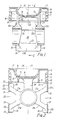
- this piston comprises a crown 10 surrounded by a ring band 11 and having two gudgeon pin bosses 12a, 12b.
- the crown 10 is provided with a depression 13 which receives a precision cast steel combustion bowl 14 having on its undersurface projections 15 which space the bowl 14 from the depression 13 and so form an insulating air gap 16 therebetween.
- the combustion bowl 14 is a shrink- fit in the depression.
- the crown 10 also has an annular outer surface which is spray-coated with a suitable ceramic 17 to a depth of 2mm in order to provide a heat-resistant coating on the crown 10.
- the ring band 11 depends from the crown 10 and is formed with a plurality of piston ring grooves 18. Webs 19 are provided between the crown 10 and the ring band 11 in order to provide a ring band with the required rigidity.
- a support 20 extends upwardly from each gudgeon pin boss 12a, 12b and is connected to the undersurface of the depression 13 in order to support the crown 10 and the ring band 11 on the gudgeon pin bosses 12a, 12b.
- Each gudgeon pin boss 12a, 12b is also formed with four struts 21 a, 21 b, 21 c, 21 d. Two of these struts 21 a, 21 b extend upwardly and outwardly from the associated gudgeon pin boss 12a, 12b on opposite sides thereof (see Fig. 2). The other two struts 21 c, 21 d extend downwardly and outwardly from the associated boss 12a, 12b on opposite sides thereof (see also Fig. 2).
- Each pair of struts 21 carries an associated arcuate skirt portion 22.
- Each arcuate skirt portion 22 has circumferentially extending upper and lower edges 23, 24 which lie in respective planes normal to the piston axis 26. These circumferential edges 23, 24 are interconnected by side edges 26 which lie in respective planes including a piston axis so that each arcuate skirt portion 22 is the shape of a segment of a cylinder.
- Each arcuate skirt portion 22 is symmetrically disposed about a plane including the piston axis and normal to the gudgeon pin bore axis (the plane of the section of Fig. 2) and is of limited arcuate extent. This extent may be between 70 ° and 110 ° but is preferably 80 ° .
- each gap 25 is constant.
- the axis 28 of the depression 13 and the combustion bowl 14 are symmetrical about an axis 28 which is offset from a vertical plane including the gudgeon pin bore axis 27. This is to provide a correct positioning of the combustion bowl 14 in relation to a fuel injector of the associated Diesel engine.
- the piston of Figures 1 and 2 reciprocates in a cylinder of an internal combustion engine, mounted on a connecting rod by a gudgeon pin extending through the gudgeon pin bosses 12a, 12b.
- the limited arcuate extent of the arcuate skirt portions 22 and their spaced support on the associated struts 21 allow the arcuate skirt portions 22 readily to adapt to the cross-sectional shape of an associated cylinder or liner.
- the arcuate skirt portions 22 are connected to the gudgeon pin bosses 12a, 12b and are not connected directly to the crown 10, the temperature of these parts is much reduced in comparison with pistons where the skirt is connected directly to the crown.
- the piston is light in weight because the traditional full cylindrical skirt is dispensed with. Due to its conformability, the piston can be fitted more closely within an associated cylinder or liner than conventional full-skirted pistons and this tends to reduce the noisiness of the engine.
- the arcuate skirt portions provide a reduced area of contact between the piston and the associated cylinder or liner, in comparison with a piston having a cylindrical skirt, it has been found that these arcuate skirt portions are adequately lubricated at all times and that there is no mixed or boundary lubrication. This is due partly to the provision of wide gaps 25 which allow oil, thrown-up from the sump of the associated engine, to pass onto the cylinder liner wall.
- the circumferential edges of the arcuate skirt portions may, be provided with hydrodynamic ramps having a ramp angle of no more than 20. These, in co-operation with the associated cylinder or liner, provide a hydrodynamic wedge action which foxes oil on the cylinder or liner over the bearing surfaces of the acruate skirt portions and thus ensures hydrodynamic lubrication under all conditions.
- the crown 10 is not insulated by any ceramic material and the combustion bowl 29 is formed directly in the crown surface. In use, this piston operates in substantially the same way as the piston of Figures 1 and 2.
Landscapes
- Engineering & Computer Science (AREA)
- General Engineering & Computer Science (AREA)
- Chemical & Material Sciences (AREA)
- Combustion & Propulsion (AREA)
- Mechanical Engineering (AREA)
- Pistons, Piston Rings, And Cylinders (AREA)
Claims (4)
Applications Claiming Priority (3)
| Application Number | Priority Date | Filing Date | Title |
|---|---|---|---|
| GB8423050 | 1984-09-12 | ||
| GB848423050A GB8423050D0 (en) | 1984-09-12 | 1984-09-12 | Pistons |
| PCT/GB1985/000416 WO1986001858A1 (en) | 1984-09-12 | 1985-09-12 | Improvements in or relating to pistons |
Publications (3)
| Publication Number | Publication Date |
|---|---|
| EP0193591A1 EP0193591A1 (de) | 1986-09-10 |
| EP0193591B1 EP0193591B1 (de) | 1989-01-04 |
| EP0193591B2 true EP0193591B2 (de) | 1994-11-09 |
Family
ID=10566624
Family Applications (1)
| Application Number | Title | Priority Date | Filing Date |
|---|---|---|---|
| EP85904653A Expired - Lifetime EP0193591B2 (de) | 1984-09-12 | 1985-09-12 | Verbesserungen an kolben |
Country Status (8)
| Country | Link |
|---|---|
| US (1) | US4702151A (de) |
| EP (1) | EP0193591B2 (de) |
| JP (1) | JPH0713496B2 (de) |
| KR (1) | KR950000916B1 (de) |
| CA (1) | CA1252677A (de) |
| DE (1) | DE3567244D1 (de) |
| GB (2) | GB8423050D0 (de) |
| WO (1) | WO1986001858A1 (de) |
Families Citing this family (21)
| Publication number | Priority date | Publication date | Assignee | Title |
|---|---|---|---|---|
| JPH0415968Y2 (de) * | 1985-10-18 | 1992-04-09 | ||
| DE3542800C1 (de) * | 1985-12-04 | 1987-05-14 | Mahle Gmbh | Zweiteiliger Tauchkolben,insbesondere fuer Verbrennungsmotoren |
| GB8606998D0 (en) * | 1986-03-20 | 1986-04-23 | Ae Plc | Pistons |
| DE3609752A1 (de) * | 1986-03-22 | 1987-10-01 | Kloeckner Humboldt Deutz Ag | Thermisch isolierter kolben |
| JPS6373551U (de) * | 1986-10-31 | 1988-05-17 | ||
| BR8700642A (pt) * | 1987-02-09 | 1988-08-30 | Metal Leve Sa | Embolo articulado |
| GB8724026D0 (en) * | 1987-10-13 | 1987-11-18 | T & N Technology Ltd | Pistons |
| GB8824222D0 (en) * | 1988-10-15 | 1988-11-23 | Wellworthy Ltd | Pistons |
| JP2561798Y2 (ja) * | 1989-05-22 | 1998-02-04 | 株式会社ユニシアジェックス | エンジン用ピストン |
| DE4122921C2 (de) * | 1990-07-18 | 1999-04-08 | Mahle Gmbh | Tauchkolben für Verbrennungsmotoren mit ballig ovaler Außenform des Kolbenschaftes |
| DE19547157A1 (de) * | 1995-12-16 | 1997-06-19 | Mahle Gmbh | Kolben-Zylinder-Baueinheit |
| DE19629399B4 (de) * | 1996-07-20 | 2008-10-16 | Mahle Gmbh | Kolben für Verbrennungsmotoren mit einem Kolbenboden oder Kolbenoberteil |
| US7406941B2 (en) * | 2004-07-21 | 2008-08-05 | Federal - Mogul World Wide, Inc. | One piece cast steel monobloc piston |
| US8474366B2 (en) * | 2007-08-13 | 2013-07-02 | Federal-Mogul Corporation | Piston with a skirt having oil flow slots and method of construction thereof |
| US8042453B2 (en) * | 2007-08-13 | 2011-10-25 | Federal-Mogul Corporation | Piston with a skirt having oil flow slots |
| EP2344744A1 (de) | 2008-10-13 | 2011-07-20 | Delaware Capital Formation, Inc. | Kolben mit verbessertem seitenbelastungswiderstand |
| USD645883S1 (en) | 2009-10-27 | 2011-09-27 | Federal-Mogul Corporation | Piston lower crown |
| EP2623760B1 (de) * | 2012-01-27 | 2017-08-02 | BRP-Rotax GmbH & Co. KG | Kolben für einen Verbrennungsmotor |
| US8662026B2 (en) | 2012-02-10 | 2014-03-04 | Federal-Mogul Corporation | Piston with supplemental cooling gallery and internal combustion engine therewith |
| DE102012014193A1 (de) * | 2012-07-18 | 2014-05-15 | Mahle International Gmbh | Kolben für einen Verbrennungsmotor |
| US10151269B2 (en) | 2016-06-16 | 2018-12-11 | GM Global Technology Operations LLC | Mass efficient piston |
Family Cites Families (15)
| Publication number | Priority date | Publication date | Assignee | Title |
|---|---|---|---|---|
| GB201142A (en) * | 1923-04-19 | 1924-09-19 | Hermann Francois Antoine Sprin | Pistons for explosion motors |
| GB266343A (en) * | 1926-02-18 | 1927-08-18 | Weiss Johann | Improvements in and relating to pistons particularly pistons for internal combustionengines |
| US2066613A (en) * | 1926-03-01 | 1937-01-05 | Ray E Day | Piston |
| US1774396A (en) * | 1927-03-04 | 1930-08-26 | Noble Warren | Piston |
| US1842910A (en) * | 1928-04-05 | 1932-01-26 | Lister William | Piston |
| US2032849A (en) * | 1934-10-15 | 1936-03-03 | Arthur A Nelson | Piston |
| FR720172A (fr) * | 1950-07-25 | 1932-02-16 | Budd Int Corp | Perfectionnements à la soudure |
| FR1394022A (fr) * | 1963-10-28 | 1965-04-02 | Piston léger rationnel pour moteurs et toutes machines | |
| DE2058410A1 (de) * | 1970-11-27 | 1972-06-08 | Daimler Benz Ag | Kolben fuer Brennkraftmaschinen |
| US3987709A (en) * | 1975-04-07 | 1976-10-26 | Day Ray E | Piston |
| AU503148B2 (en) * | 1975-06-16 | 1979-08-23 | Cummins Engine Company, Inc | Piston with flexible heat dam |
| DE2949091A1 (de) * | 1979-12-06 | 1981-06-11 | Karl Schmidt Gmbh, 7107 Neckarsulm | Leichtmetall-regelkolben |
| DE3039382A1 (de) * | 1980-10-18 | 1982-04-22 | Mahle Gmbh, 7000 Stuttgart | Leichter tachkolben fuer verbrennungsmotoren |
| IT1144621B (it) * | 1981-07-31 | 1986-10-29 | Ae Borgo Spa | Perfezionamento relativo all architettura degli stantuffi per motori endotermici |
| GB8403522D0 (en) * | 1984-02-10 | 1984-03-14 | Ae Plc | Pistons |
-
1984
- 1984-09-12 GB GB848423050A patent/GB8423050D0/en active Pending
-
1985
- 1985-09-11 GB GB08522476A patent/GB2164419B/en not_active Expired
- 1985-09-12 JP JP60504103A patent/JPH0713496B2/ja not_active Expired - Lifetime
- 1985-09-12 US US06/860,318 patent/US4702151A/en not_active Expired - Lifetime
- 1985-09-12 CA CA000490570A patent/CA1252677A/en not_active Expired
- 1985-09-12 WO PCT/GB1985/000416 patent/WO1986001858A1/en not_active Ceased
- 1985-09-12 DE DE8585904653T patent/DE3567244D1/de not_active Expired
- 1985-09-12 KR KR1019860700230A patent/KR950000916B1/ko not_active Expired - Fee Related
- 1985-09-12 EP EP85904653A patent/EP0193591B2/de not_active Expired - Lifetime
Also Published As
| Publication number | Publication date |
|---|---|
| KR860700280A (ko) | 1986-08-01 |
| EP0193591A1 (de) | 1986-09-10 |
| EP0193591B1 (de) | 1989-01-04 |
| GB2164419B (en) | 1988-04-07 |
| DE3567244D1 (en) | 1989-02-09 |
| GB8522476D0 (en) | 1985-10-16 |
| JPS62500186A (ja) | 1987-01-22 |
| WO1986001858A1 (en) | 1986-03-27 |
| KR950000916B1 (ko) | 1995-02-03 |
| CA1252677A (en) | 1989-04-18 |
| GB2164419A (en) | 1986-03-19 |
| US4702151A (en) | 1987-10-27 |
| JPH0713496B2 (ja) | 1995-02-15 |
| GB8423050D0 (en) | 1984-10-17 |
Similar Documents
| Publication | Publication Date | Title |
|---|---|---|
| EP0193591B2 (de) | Verbesserungen an kolben | |
| EP0364810B1 (de) | Kolben | |
| US6357341B1 (en) | Piston of internal combustion engine | |
| CA1037802A (en) | Piston assembly | |
| EP0071361B1 (de) | Kolben für eine Brennkraftmaschine | |
| US4466399A (en) | Piston-cylinder set for reciprocating internal-combustion engines, especially Otto and diesel engines | |
| EP0238146B1 (de) | Kolben | |
| US4599935A (en) | Plunger piston for internal combustion engines | |
| GB2148451A (en) | Structure of internal-combustion engine piston | |
| EP0188108B1 (de) | Kolben | |
| US4751871A (en) | Multisectional piston with plural ceramic parts and rigidly connected piston rod for use in horizontally opposed piston internal combustion engine | |
| KR900004612B1 (ko) | 피스톤 | |
| JPH0337026B2 (de) | ||
| EP0238152B1 (de) | Kolben für eine Brennkraftmaschine | |
| WO1986005249A1 (en) | Pistons | |
| CA1255553A (en) | Pistons | |
| US5809946A (en) | Structure of an open deck type cylinder block | |
| GB2162614A (en) | Bearing surfaces for internal combustion engine pistons | |
| JPH0148386B2 (de) | ||
| GB2050563A (en) | Pistons and Cylinder Liners | |
| CA1092453A (en) | Piston for an internal combustion engine | |
| WO1993006389A1 (en) | Piston for use in an engine or motor |
Legal Events
| Date | Code | Title | Description |
|---|---|---|---|
| PUAI | Public reference made under article 153(3) epc to a published international application that has entered the european phase |
Free format text: ORIGINAL CODE: 0009012 |
|
| 17P | Request for examination filed |
Effective date: 19860502 |
|
| AK | Designated contracting states |
Kind code of ref document: A1 Designated state(s): DE FR IT NL SE |
|
| 17Q | First examination report despatched |
Effective date: 19870422 |
|
| GRAA | (expected) grant |
Free format text: ORIGINAL CODE: 0009210 |
|
| AK | Designated contracting states |
Kind code of ref document: B1 Designated state(s): DE FR IT NL SE |
|
| PG25 | Lapsed in a contracting state [announced via postgrant information from national office to epo] |
Ref country code: NL Effective date: 19890104 |
|
| REF | Corresponds to: |
Ref document number: 3567244 Country of ref document: DE Date of ref document: 19890209 |
|
| ET | Fr: translation filed | ||
| ITF | It: translation for a ep patent filed | ||
| NLV1 | Nl: lapsed or annulled due to failure to fulfill the requirements of art. 29p and 29m of the patents act | ||
| PLBI | Opposition filed |
Free format text: ORIGINAL CODE: 0009260 |
|
| 26 | Opposition filed |
Opponent name: MAHLE GMBH Effective date: 19891003 |
|
| ITTA | It: last paid annual fee | ||
| PUAH | Patent maintained in amended form |
Free format text: ORIGINAL CODE: 0009272 |
|
| STAA | Information on the status of an ep patent application or granted ep patent |
Free format text: STATUS: PATENT MAINTAINED AS AMENDED |
|
| 27A | Patent maintained in amended form |
Effective date: 19941109 |
|
| AK | Designated contracting states |
Kind code of ref document: B2 Designated state(s): DE FR IT NL SE |
|
| ITF | It: translation for a ep patent filed | ||
| EAL | Se: european patent in force in sweden |
Ref document number: 85904653.4 |
|
| ET3 | Fr: translation filed ** decision concerning opposition | ||
| APAC | Appeal dossier modified |
Free format text: ORIGINAL CODE: EPIDOS NOAPO |
|
| APAC | Appeal dossier modified |
Free format text: ORIGINAL CODE: EPIDOS NOAPO |
|
| PGFP | Annual fee paid to national office [announced via postgrant information from national office to epo] |
Ref country code: FR Payment date: 20000807 Year of fee payment: 16 |
|
| PGFP | Annual fee paid to national office [announced via postgrant information from national office to epo] |
Ref country code: SE Payment date: 20000814 Year of fee payment: 16 |
|
| PGFP | Annual fee paid to national office [announced via postgrant information from national office to epo] |
Ref country code: DE Payment date: 20000823 Year of fee payment: 16 |
|
| PG25 | Lapsed in a contracting state [announced via postgrant information from national office to epo] |
Ref country code: SE Free format text: LAPSE BECAUSE OF NON-PAYMENT OF DUE FEES Effective date: 20010913 |
|
| PG25 | Lapsed in a contracting state [announced via postgrant information from national office to epo] |
Ref country code: DE Free format text: LAPSE BECAUSE OF NON-PAYMENT OF DUE FEES Effective date: 20020501 |
|
| EUG | Se: european patent has lapsed |
Ref document number: 85904653.4 |
|
| PG25 | Lapsed in a contracting state [announced via postgrant information from national office to epo] |
Ref country code: FR Free format text: LAPSE BECAUSE OF NON-PAYMENT OF DUE FEES Effective date: 20020531 |
|
| REG | Reference to a national code |
Ref country code: FR Ref legal event code: ST |
|
| APAH | Appeal reference modified |
Free format text: ORIGINAL CODE: EPIDOSCREFNO |