EP0193149A1 - Joint mechanism for manipulators - Google Patents
Joint mechanism for manipulators Download PDFInfo
- Publication number
- EP0193149A1 EP0193149A1 EP86102353A EP86102353A EP0193149A1 EP 0193149 A1 EP0193149 A1 EP 0193149A1 EP 86102353 A EP86102353 A EP 86102353A EP 86102353 A EP86102353 A EP 86102353A EP 0193149 A1 EP0193149 A1 EP 0193149A1
- Authority
- EP
- European Patent Office
- Prior art keywords
- actuator
- shoulder frame
- bevel gear
- arm
- joint mechanism
- Prior art date
- Legal status (The legal status is an assumption and is not a legal conclusion. Google has not performed a legal analysis and makes no representation as to the accuracy of the status listed.)
- Granted
Links
- 230000007246 mechanism Effects 0.000 title claims abstract description 37
- 210000000323 shoulder joint Anatomy 0.000 abstract description 10
- 210000002310 elbow joint Anatomy 0.000 abstract description 7
- 210000001503 joint Anatomy 0.000 description 6
- 230000000712 assembly Effects 0.000 description 2
- 238000000429 assembly Methods 0.000 description 2
- 125000006414 CCl Chemical group ClC* 0.000 description 1
- 230000001133 acceleration Effects 0.000 description 1
Images

Classifications
-
- B—PERFORMING OPERATIONS; TRANSPORTING
- B25—HAND TOOLS; PORTABLE POWER-DRIVEN TOOLS; MANIPULATORS
- B25J—MANIPULATORS; CHAMBERS PROVIDED WITH MANIPULATION DEVICES
- B25J9/00—Programme-controlled manipulators
- B25J9/0084—Programme-controlled manipulators comprising a plurality of manipulators
- B25J9/0087—Dual arms
-
- B—PERFORMING OPERATIONS; TRANSPORTING
- B25—HAND TOOLS; PORTABLE POWER-DRIVEN TOOLS; MANIPULATORS
- B25J—MANIPULATORS; CHAMBERS PROVIDED WITH MANIPULATION DEVICES
- B25J15/00—Gripping heads and other end effectors
- B25J15/0052—Gripping heads and other end effectors multiple gripper units or multiple end effectors
-
- B—PERFORMING OPERATIONS; TRANSPORTING
- B25—HAND TOOLS; PORTABLE POWER-DRIVEN TOOLS; MANIPULATORS
- B25J—MANIPULATORS; CHAMBERS PROVIDED WITH MANIPULATION DEVICES
- B25J19/00—Accessories fitted to manipulators, e.g. for monitoring, for viewing; Safety devices combined with or specially adapted for use in connection with manipulators
- B25J19/0008—Balancing devices
- B25J19/002—Balancing devices using counterweights
-
- B—PERFORMING OPERATIONS; TRANSPORTING
- B25—HAND TOOLS; PORTABLE POWER-DRIVEN TOOLS; MANIPULATORS
- B25J—MANIPULATORS; CHAMBERS PROVIDED WITH MANIPULATION DEVICES
- B25J9/00—Programme-controlled manipulators
- B25J9/0006—Exoskeletons, i.e. resembling a human figure
-
- B—PERFORMING OPERATIONS; TRANSPORTING
- B25—HAND TOOLS; PORTABLE POWER-DRIVEN TOOLS; MANIPULATORS
- B25J—MANIPULATORS; CHAMBERS PROVIDED WITH MANIPULATION DEVICES
- B25J9/00—Programme-controlled manipulators
- B25J9/0084—Programme-controlled manipulators comprising a plurality of manipulators
-
- B—PERFORMING OPERATIONS; TRANSPORTING
- B25—HAND TOOLS; PORTABLE POWER-DRIVEN TOOLS; MANIPULATORS
- B25J—MANIPULATORS; CHAMBERS PROVIDED WITH MANIPULATION DEVICES
- B25J9/00—Programme-controlled manipulators
- B25J9/02—Programme-controlled manipulators characterised by movement of the arms, e.g. cartesian coordinate type
- B25J9/04—Programme-controlled manipulators characterised by movement of the arms, e.g. cartesian coordinate type by rotating at least one arm, excluding the head movement itself, e.g. cylindrical coordinate type or polar coordinate type
Definitions
- the present invention relates to a joint mechanism used with robots, manipulators, etc., and more specifically to the joint mechanism for driving right and left upper arms and lower arms freely and independently in multi-directions.
- the motors are concentratedly disposed on an appropriate position and one joint is driven by way of the other joints. Therefore, when the upper or lower arms are required to drive in predetermined directions, there exist problems in that plural joints should be driven simultaneously. That is, it is impossible to drive a joint independently without relation to other joints or without interference in movement between joints.
- the shoulder joint should be such that the pivotal axis of the arm is located on a straight line connecting the shoulder and the hand or fingers and the arm is pivoted about a horizontal pivotal axis perpendicular to the above straight line.
- the joint mechanism for a manipulator including a manipulator base, a shoulder frame, an upper arm, and a lower arm comprises: (a) a first actuator mounted on the shoulder frame; (b) a second actuator mounted on the shoulder frame; (c) a third actuator mounted on the shoulder frame; (d) a first gear assembly housed within the shoulder frame for moving the shoulder frame back and forth together with the upper and lower arms when said first actuator is driven; (e) a second gear assembly housed within the shoulder frame for moving the upper and lower arms clockwise or counterclockwise when said second actuator is driven; and (f) a third gear assembly housed within the lower arm for moving only the lower arm back and forth or up and down when said third actuator is driven.
- the shoulder frame is moved back and forth by the first actuator; the upper and lower arms are moved clockwise or counterclockwise by the second actuator; and only the lower arm is moved back and forth or up and down by the third actuator, respectively and independently.
- a balance weight and a balance weight gear assembly are attached to the upper portion of the upper arm and driven by the third actuator in order to keep momental balance of the lower arms when the lower arm is moved.
- a fourth actuator and a fourth gear assembly are provided for further moving the shoulder frame right and left.
- each actuator is arranged on the shoulder frame of the manipulator, and each joint (gear assembly) is driven independently in multi-directions without interference in movement with other joints (gear assemblies) in the manner similar to human shoulder and elbow joints.
- the joint mechanism shown in Fig. 1 is roughly made up of a manipulator base 10, a shoulder frame 20, an upper arm 30, a lower arm 40, a balance weight 31, a first actuator 50 for a first drive mode of the (A-A') direction, a second actuator 60 for a second drive mode of the (B-B') direction, and a third actuator 70 for a third drive mode of the (C-C l ) direction.
- Each actuator 50, 60 or 70 is composed of a motor, a speed reducing gear, etc. and mounted on the shoulder frame 20.
- the balance weight 31 is mounted on the upper side of the upper arm 30 so as to keep weight balance of the arm relative to three actuators and other elements.
- the second actuator 60 is provided with a spur gear 61 housed within the shoulder frame 20.
- a spur gear 32 is fixed to top of the upper arm 30 in mesh with the spur gear 61. Therefore, when the second actuator 60 such as a motor drives the spur gear 61, the spur gear 32 is rotated, so that the whole arm assembly including the upper arm 30, the lower arm 40, the third actuator 70, and the balance weight 31 are all pivoted in either (B-B') direction as depicted in Fig. l.
- the third actuator 70 such as a motor rotates the shaft 71
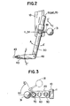
- the bevel gear 72 is rotated, so that the lower arm 40 is pivoted or swung via the bevel gear 41 in the back and forth or up and down (C-C') direction as depicted Fig. 2.
- the drive shaft 71 is loosely passed through the center hole of the spur gear 32, the spur gear 32 is never driven by the third actuator 70 itself.
- the two bevel gears 41 and 72 for pivoting the lower arm 40 are the same in diameter and module as those 37 and 73 for pivoting the balance weight 31, the pivot angles of both are equal to each other for keeping the momental balance between the lower arm 40 and the balance weight 31.
- the shoulder frame support axle 11 about which the shoulder frame 20 is pivoted back and forth is located at the same height on the same plane as that of the balance weight support axle 34 about which the balance weight 31 is pivoted.
- Fig. 3 shows the case where both the upper and lower arms 30 and 40 are pivoted in the (B-B') direction by the second actuator 60 and further only the lower arm 40 (not shown) is pivoted frontward and therefore the balance weight 31 is pivoted rearward to keep the momental balance between the lower arm 40 and the balance weight 31. Therefore, the balance weight 31 is effective when the lower arm 40 is pivoted in either direction.
- the balance weight 31 is disposed near the shoulder portion so as not to obstruct the way of operation area of the manipulator. In human, the arm is moved back and forth or twisted with the shoulder as its center. Although the above motion is ideal, it is impossible to realize the above motion in robots or manipulators.
- the aim of this invention is to realize the arm motion as closely to the human motion as possible.
- the reference numeral 43 shown in Fig. 2 denotes fingers of the manipulator. These fingers are driven by another actuator (not shown) housed within the lower arm 40. The detail of the finger actuator are not described herein because not being directly related to the present invention.
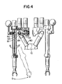
- the joint mechanism further includes a fourth actuator 80 to pivot the shoulder frame 20 in the (D-D') direction.
- the fourth actuator 80 such as a motor is provided with a bevel gear 81.
- Another bevel gear 82 is pivotably supported by a second shoulder frame support axle 83 fixed to a base plate 84 extending from the base 10 in mesh with the bevel gear 81.
- the first shoulder frame support axle 11A is fixed to the bevel gear 82.
- the joint mechanism for manipulators according to the present invention has the following features:
Abstract
Description
- The present invention relates to a joint mechanism used with robots, manipulators, etc., and more specifically to the joint mechanism for driving right and left upper arms and lower arms freely and independently in multi-directions.
- In robots or manipulators, there are provided mechanisms for driving shoulder joints to move upper arms and mechanisms for driving elbow joints to move only lower arms. Actuators or motors included in these mechanisms are usually arranged concentratively at a position (called concentrated actuator arrangement system) or separately at some positions (called separated actuator arrangement system).
- In the concentrated actuator arrangement system, the motors are concentratedly disposed on an appropriate position and one joint is driven by way of the other joints. Therefore, when the upper or lower arms are required to drive in predetermined directions, there exist problems in that plural joints should be driven simultaneously. That is, it is impossible to drive a joint independently without relation to other joints or without interference in movement between joints.
- In the separated actuator arrangement system, since each motor is arranged at each joint, there exist problems in that it is rather difficult to keep balance of the arm in relation to the motor weight. Further, the balance weight is inevitably increased, thus causing an increase in dimensions or weight. In addition, another problem arises such that when the weight of the arm increases, it is necessary to increase the rigidity of the arm so that the arm can withstand acceleration or deceleration caused when moved quickly.
- In addition, there exists another manipulator such that the shoulder joint is only pivoted and the drive shaft is arranged eccentrically with respect to the center line of the arm. In the manipulator of this type, since the rotational axis of the upper arm about the shoulder joint and the pivotal axis thereof in the back and forth direction are located at two different positions, it is difficult to manipulate or operate the manipulator by use of operation rods in the case of feedback control system.
- In summary, it is ideal to construct and operate the manipulator joints as humanly as possible. In practice, the shoulder joint should be such that the pivotal axis of the arm is located on a straight line connecting the shoulder and the hand or fingers and the arm is pivoted about a horizontal pivotal axis perpendicular to the above straight line.
- In the prior-art manipulators, it has been difficult to realize a humanized shoulder joint motion and a humanized elbow joint motion. In other words, there exists no manipulator easy for the operator to handle in accordance with human sense.
- With these problems in mind, therefore, it is the primary object of the present invention to provide a joint mechanism for driving the upper and lower arms used with a robot or manipulator which is constructed and operable as humanly as possible.
- To achieve the above-mentioned object, the joint mechanism for a manipulator including a manipulator base, a shoulder frame, an upper arm, and a lower arm according to the present invention comprises: (a) a first actuator mounted on the shoulder frame; (b) a second actuator mounted on the shoulder frame; (c) a third actuator mounted on the shoulder frame; (d) a first gear assembly housed within the shoulder frame for moving the shoulder frame back and forth together with the upper and lower arms when said first actuator is driven; (e) a second gear assembly housed within the shoulder frame for moving the upper and lower arms clockwise or counterclockwise when said second actuator is driven; and (f) a third gear assembly housed within the lower arm for moving only the lower arm back and forth or up and down when said third actuator is driven.
- In the joint mechanism for a manipulator according to the present invention, the shoulder frame is moved back and forth by the first actuator; the upper and lower arms are moved clockwise or counterclockwise by the second actuator; and only the lower arm is moved back and forth or up and down by the third actuator, respectively and independently.
- Further, a balance weight and a balance weight gear assembly are attached to the upper portion of the upper arm and driven by the third actuator in order to keep momental balance of the lower arms when the lower arm is moved.
- Further, a fourth actuator and a fourth gear assembly are provided for further moving the shoulder frame right and left.
- The pivotal center of said first gear assembly and the pivotal center of said balance weight gear assembly lie on a straight lie. The first, second and third actuators are disposed above the pivotal center of said first gear assembly and the third actuator is disposed over the upper arm. The balance weight is disposed above the pivotal center of said first gear assembly.
- In summary, in the joint mechanism for a manipulator according to the present invention, each actuator is arranged on the shoulder frame of the manipulator, and each joint (gear assembly) is driven independently in multi-directions without interference in movement with other joints (gear assemblies) in the manner similar to human shoulder and elbow joints.
- The features and advantages of the joint mechanism for an manipulator according to the present invention will be more clearly appreciated from the following description of the preferred embodiments of the invention taken in conjunction with the accompanying drawings in which like reference numerals designate the same or similar elements or sections throughout the figures thereof and in which:
- Fig. 1 is a front view showing a first embodiment of the joint mechanism of a manipulator according to the present invention, in which only the righthand portion thereof is shown by a cross-sectional view;
- Fig. 2 is a side view of the joint mechanism shown in Fig. 1;
- Fig. 3 is a top view of the joint mechanism shown in Fig. 1; and
- Fig. 4 is a front view showing a second embodiment of the joint mechanism of a manipulator according to the present invention, in which only the righthand portion thereof is shown by a cross-sectional view.
- Fig. 1 shows a first embodiment of the present invention. In Fig. 1, a pair of arms and two sets of arm driving joint mechanisms are shown. However, only the lefthand arm and lefthand joint mechanisms of the manipulator (when seen from the back) will be described hereinafter, because the righthand arm and righthand joint mechanisms are the same as the lefthand ones being disposed mirror symmetrically.
- In this first embodiment, the joint mechanism serves to drive the arm in three operational modes: pivotal movement of upper and lower arms in the back and forth (A-A') direction (perpendicular to the plane of Fig. 1) as shown in Fig. 2, pivotal movement of upper and lower arms in the (B-B') direction as shown in Fig. 1; and pivotal movement of only the lower arm in the back and forth or up and down (C-C') direction as shown in Fig. 2.
- The joint mechanism shown in Fig. 1 is roughly made up of a
manipulator base 10, ashoulder frame 20, anupper arm 30, alower arm 40, abalance weight 31, afirst actuator 50 for a first drive mode of the (A-A') direction, asecond actuator 60 for a second drive mode of the (B-B') direction, and athird actuator 70 for a third drive mode of the (C-Cl) direction. - Each
actuator shoulder frame 20. Thebalance weight 31 is mounted on the upper side of theupper arm 30 so as to keep weight balance of the arm relative to three actuators and other elements. - : The
manipulator base 10 is provided with a shoulder frame support axle 11 for supporting the shoulder frame horizontally. This support axle also supports the whole shoulder assembly. Abevel gear 12 is fixed to this shoulder frame support axle 11 being housed within theshoulder frame 20. Theshoulder frame 20 is pivotably supported by the shoulder frame support axle 11 via a pair ofbearings first actuator 50 is provided with a bevel gear.51 being in mesh with thebevel gear 12 within theshoulder frame 20. Therefore, when thefirst actuator 50 such as a motor drives thebevel gear 51 in either direction, thisbevel gear 51 moves along the circumference of thefixed bevel gear 12, so that the whole shoulder assembly is pivoted or swung with the shoulder frame support axle 11 as its center in the back and forth (A-A') direction as depicted in Fig. 2. - The
second actuator 60 is provided with aspur gear 61 housed within theshoulder frame 20. Aspur gear 32 is fixed to top of theupper arm 30 in mesh with thespur gear 61. Therefore, when thesecond actuator 60 such as a motor drives thespur gear 61, thespur gear 32 is rotated, so that the whole arm assembly including theupper arm 30, thelower arm 40, thethird actuator 70, and thebalance weight 31 are all pivoted in either (B-B') direction as depicted in Fig. l. - The
third actuator 70 is pivotably supported via twobearings shoulder frame 20. Thisthird actuator 70 is fixedly mounted on thespur gear 32. A long actuator shaft 71 extends within theupper arm 30 being loosely passed through a center hole (not shown) formed in thespur gear 32. Asmall bevel gear 72 is fixed to the lower end of this shaft 71. Thisbevel gear 72 is in mesh with anothersmall bevel gear 41 fixed to the upper end of thelower arm 40. A lowerarm support axle 42 is fixed to the center of thebevel gear 41 at one end thereof and pivotably supported at its lower end via a set ofbearings 43. Therefore, when thethird actuator 70 such as a motor rotates the shaft 71, thebevel gear 72 is rotated, so that thelower arm 40 is pivoted or swung via thebevel gear 41 in the back and forth or up and down (C-C') direction as depicted Fig. 2. Here, it should be noted that since the drive shaft 71 is loosely passed through the center hole of thespur gear 32, thespur gear 32 is never driven by thethird actuator 70 itself. - Further, another
small bevel gear 73 is fixed to the shaft 71 near the top of theupper arm 30. Abalance weight axle 34 is pivotably supported via twobearings 35 disposed in a horizontally cylindricalupper arm frame 36. Asmall bevel gear 37 is fixed to thebalance weight axle 34 at one end thereof in mesh with thebevel gear 73. Abalance weight rod 38 is fixed to thebalance weight axle 34 at the other end thereof. Therefore, when thethird actuator 70 rotates the shaft 71 to pivot thelower arm 40 with theaxle 42 as its center, thebalance weight 31 is also pivoted in. the same direction as that of thelower arm 40, so that the momental balance due to weight between thelower arm 40 and thebalance weight 31 is maintained as depicted in Fig. 2. - Here, since the two
bevel gears lower arm 40 are the same in diameter and module as those 37 and 73 for pivoting thebalance weight 31, the pivot angles of both are equal to each other for keeping the momental balance between thelower arm 40 and thebalance weight 31. Further, it should be noted that the shoulder frame support axle 11 about which theshoulder frame 20 is pivoted back and forth is located at the same height on the same plane as that of the balanceweight support axle 34 about which thebalance weight 31 is pivoted. - Further, since the shoulder frame support axle 11 about which the
shoulder frame 20 is pivoted back and forth and the shaft 71 about which both thearms fingers 43 are located on the extension line of the shaft 71, the above arrangement permits the movement similar to that of human shoulder joint and elbow joint. - In the above description, the first gear assembly including two
bevel gears spur gears bevel gears - Fig. 3 shows the case where both the upper and
lower arms second actuator 60 and further only the lower arm 40 (not shown) is pivoted frontward and therefore thebalance weight 31 is pivoted rearward to keep the momental balance between thelower arm 40 and thebalance weight 31. Therefore, thebalance weight 31 is effective when thelower arm 40 is pivoted in either direction. In this embodiment, it is necessary to decide the magnitude ofbalance weight 31 and the length of thebalance rod 38 under consideration of various factors as weights and lengths of the upper andlower arms actuators balance weight 31 is disposed near the shoulder portion so as not to obstruct the way of operation area of the manipulator. In human, the arm is moved back and forth or twisted with the shoulder as its center. Although the above motion is ideal, it is impossible to realize the above motion in robots or manipulators. The aim of this invention is to realize the arm motion as closely to the human motion as possible. - As well understood by the above description, since the three pivotal movements of the arm (in the (A-A') direction that the arm is pivoted back and forth about the shoulder frame support axle 11, in the (B-B') direction that the arm is pivoted clockwise or counterclockwise about the shaft 71, and in the (C-C') direction that the lower arm is pivoted back and forth or up and down about the lower arm support axle 42) are all achieved independently, it is possible to drive, stop or control each actuator 50, 60 or 70 separately.
- Further, the
reference numeral 43 shown in Fig. 2 denotes fingers of the manipulator. These fingers are driven by another actuator (not shown) housed within thelower arm 40. The detail of the finger actuator are not described herein because not being directly related to the present invention. - Fig. 4. shows a second embodiment of the present invention. In this embodiment, the joint mechanism serves to drive the arm in four operational modes: the pivotal movement of the upper and lower arms in the back and forth (A-A') direction, the pivotal movement of upper and lower arm in the clockwise or counterclockwise (B-B') direction, the pivotal movement of only lower arm in the back and forth or up and down (C-C') direction, and additionally the pivotal movement of the upper and lower arms in right and left (D-D') direction as depicted in Fig. 4.
- In Fig. 4, the joint mechanism further includes a
fourth actuator 80 to pivot theshoulder frame 20 in the (D-D') direction. Thefourth actuator 80 such as a motor is provided with abevel gear 81. Anotherbevel gear 82 is pivotably supported by a second shoulderframe support axle 83 fixed to a base plate 84 extending from the base 10 in mesh with thebevel gear 81. The first shoulder frame support axle 11A is fixed to thebevel gear 82. - In the first embodiment shown in Fig. 1, the shoulder frame support axle 11 is fixed to the
base 10. However, in this second embodiment shown in Fig. 4, the first shoulder frame support axle 11A is supported by the second shoulder frame support axle 11 and pivoted around the second shoulderframe support axle 83 by twobevel gears fourth actuator 80 is driven, so that the whole shoulder frame including the arms is pivoted or swung in the (D-D') direction as depicted in Fig. 4. - As described above, the joint mechanism for manipulators according to the present invention has the following features:
- (1) The three or four actuators and other elements are concentratively disposed on the shoulder section of the mechanism without obstruction of the operation range of the manipulator.
- (2) The three or four pivotal movements can be controlled independently by a simple control system without motional interference with each other.
- (3) The arrangement and movement of gear assemblies are similar to the shoulder and elbow joints of human.
- (4) The operation is free, natural and easy to handle the manipulator on the basis of the operator's sense without movement restriction.
- (5) The horizontal axis of back and forth pivotal movement of the arm is perpendicular to the vertical axis of clockwise or counterclockwise movement of the arm on a single plane as in human shoulder and further the fingers are located on an extension of the vertical axis of the clockwise movement, so that the manipulatability can be improved in the manipulator.
- (6) The balance weight is effective when the lower arm is pivoted up and down without obstruction of way of manipulation operation.
- (7) The balance weight is disposed near the shoulder section without obstruction of way of manipulation operation.
Claims (11)
Applications Claiming Priority (4)
| Application Number | Priority Date | Filing Date | Title |
|---|---|---|---|
| JP25886/85 | 1985-02-25 | ||
| JP1985025886U JPH0243671Y2 (en) | 1985-02-25 | 1985-02-25 | |
| JP25885/85 | 1985-02-25 | ||
| JP2588585U JPH035438Y2 (en) | 1985-02-25 | 1985-02-25 |
Publications (2)
| Publication Number | Publication Date |
|---|---|
| EP0193149A1 true EP0193149A1 (en) | 1986-09-03 |
| EP0193149B1 EP0193149B1 (en) | 1989-11-15 |
Family
ID=26363576
Family Applications (1)
| Application Number | Title | Priority Date | Filing Date |
|---|---|---|---|
| EP86102353A Expired EP0193149B1 (en) | 1985-02-25 | 1986-02-24 | Joint mechanism for manipulators |
Country Status (3)
| Country | Link |
|---|---|
| US (1) | US4717303A (en) |
| EP (1) | EP0193149B1 (en) |
| DE (1) | DE3666925D1 (en) |
Cited By (3)
| Publication number | Priority date | Publication date | Assignee | Title |
|---|---|---|---|---|
| CN104308859A (en) * | 2014-09-19 | 2015-01-28 | 重庆交通大学 | Heavy-load precision redundant three-arm mechanical hand based on traveling crane |
| CN106041957A (en) * | 2016-07-20 | 2016-10-26 | 北京光年无限科技有限公司 | Upper limb structure of humanoid robot and humanoid robot |
| CN109571421A (en) * | 2017-09-29 | 2019-04-05 | 克诺有限公司 | Work robot |
Families Citing this family (9)
| Publication number | Priority date | Publication date | Assignee | Title |
|---|---|---|---|---|
| US4780047A (en) * | 1985-04-05 | 1988-10-25 | Martin Marietta Energy Systems, Inc. | Advanced servo manipulator |
| US4762455A (en) * | 1987-06-01 | 1988-08-09 | Remote Technology Corporation | Remote manipulator |
| US4775289A (en) * | 1987-09-25 | 1988-10-04 | Regents Of The University Of Minnesota | Statically-balanced direct-drive robot arm |
| IT1245512B (en) * | 1991-02-15 | 1994-09-29 | Comau Spa | ARTICULATED ROBOT WITH DOUBLE FOREARM |
| KR101013792B1 (en) | 2008-09-18 | 2011-02-14 | 주식회사 로보테크 | Driving apparatus of 2 degree of freedom for robot upper-arm |
| US8496416B1 (en) * | 2009-05-21 | 2013-07-30 | The Boeing Company | Method and apparatus for drilling operations |
| US9314934B2 (en) * | 2014-02-27 | 2016-04-19 | Disney Enterprises, Inc. | Gravity-counterbalanced robot arm |
| US20190240831A1 (en) * | 2018-02-05 | 2019-08-08 | Kimball Electronics Indiana, Inc. | Robot Having Vertically Oriented Articulated Arm Motion |
| JP6770019B2 (en) * | 2018-05-10 | 2020-10-14 | ファナック株式会社 | A drive device in which a plurality of motors drive one operating axis, and a robot including a drive device |
Citations (9)
| Publication number | Priority date | Publication date | Assignee | Title |
|---|---|---|---|---|
| US2858947A (en) * | 1953-11-16 | 1958-11-04 | Garrett Corp | Remote control manipulating apparatus |
| FR1537663A (en) * | 1964-04-28 | 1968-09-07 | Programmed & Remote Syst Corp | Remote position control manipulator |
| FR2155848A1 (en) * | 1971-10-11 | 1973-05-25 | Commissariat Energie Atomique | |
| FR2183583A2 (en) * | 1972-05-10 | 1973-12-21 | Commissariat Energie Atomique | |
| US3817403A (en) * | 1972-05-10 | 1974-06-18 | Commissariat Energie Atomique | Remote manipulator |
| US3922930A (en) * | 1974-12-23 | 1975-12-02 | Nasa | Remotely operable articulated manipulator |
| US4062455A (en) * | 1976-11-22 | 1977-12-13 | Flatau Carl R | Remote manipulator |
| FR2450673A1 (en) * | 1979-03-05 | 1980-10-03 | Jungheinrich Kg | AUTOMATIC MACHINE FOR HANDLING WORKPIECES AND / OR TOOLS |
| FR2521056A1 (en) * | 1982-02-06 | 1983-08-12 | Hartmann & Laemmle | INDUSTRIAL ROBOT |
Family Cites Families (6)
| Publication number | Priority date | Publication date | Assignee | Title |
|---|---|---|---|---|
| US2061256A (en) * | 1935-01-16 | 1936-11-17 | Eugene J Romano | Submarine salvage apparatus |
| US3272347A (en) * | 1963-01-14 | 1966-09-13 | Jerome H Lemelson | Article manipulation apparatus |
| JPS5273463A (en) * | 1975-12-13 | 1977-06-20 | Kawasaki Heavy Ind Ltd | Robot for industrial use |
| SU573339A1 (en) * | 1976-06-21 | 1977-09-25 | Проектно-Конструкторское И Технологическое Бюро По Машиностроению | Robot |
| SU763082A1 (en) * | 1977-07-01 | 1980-09-15 | Предприятие П/Я Р-6930 | Modular manipulator |
| US4507043A (en) * | 1982-09-14 | 1985-03-26 | Textron, Inc. | Counterbalance robot arm |
-
1986
- 1986-02-21 US US06/832,270 patent/US4717303A/en not_active Expired - Lifetime
- 1986-02-24 DE DE8686102353T patent/DE3666925D1/en not_active Expired
- 1986-02-24 EP EP86102353A patent/EP0193149B1/en not_active Expired
Patent Citations (9)
| Publication number | Priority date | Publication date | Assignee | Title |
|---|---|---|---|---|
| US2858947A (en) * | 1953-11-16 | 1958-11-04 | Garrett Corp | Remote control manipulating apparatus |
| FR1537663A (en) * | 1964-04-28 | 1968-09-07 | Programmed & Remote Syst Corp | Remote position control manipulator |
| FR2155848A1 (en) * | 1971-10-11 | 1973-05-25 | Commissariat Energie Atomique | |
| FR2183583A2 (en) * | 1972-05-10 | 1973-12-21 | Commissariat Energie Atomique | |
| US3817403A (en) * | 1972-05-10 | 1974-06-18 | Commissariat Energie Atomique | Remote manipulator |
| US3922930A (en) * | 1974-12-23 | 1975-12-02 | Nasa | Remotely operable articulated manipulator |
| US4062455A (en) * | 1976-11-22 | 1977-12-13 | Flatau Carl R | Remote manipulator |
| FR2450673A1 (en) * | 1979-03-05 | 1980-10-03 | Jungheinrich Kg | AUTOMATIC MACHINE FOR HANDLING WORKPIECES AND / OR TOOLS |
| FR2521056A1 (en) * | 1982-02-06 | 1983-08-12 | Hartmann & Laemmle | INDUSTRIAL ROBOT |
Cited By (5)
| Publication number | Priority date | Publication date | Assignee | Title |
|---|---|---|---|---|
| CN104308859A (en) * | 2014-09-19 | 2015-01-28 | 重庆交通大学 | Heavy-load precision redundant three-arm mechanical hand based on traveling crane |
| CN104308859B (en) * | 2014-09-19 | 2016-03-23 | 重庆交通大学 | Based on the heavy-loaded precision redundancy three arm manipulator of driving |
| CN106041957A (en) * | 2016-07-20 | 2016-10-26 | 北京光年无限科技有限公司 | Upper limb structure of humanoid robot and humanoid robot |
| CN106041957B (en) * | 2016-07-20 | 2019-03-01 | 北京光年无限科技有限公司 | A kind of Arm structure and anthropomorphic robot of anthropomorphic robot |
| CN109571421A (en) * | 2017-09-29 | 2019-04-05 | 克诺有限公司 | Work robot |
Also Published As
| Publication number | Publication date |
|---|---|
| US4717303A (en) | 1988-01-05 |
| DE3666925D1 (en) | 1989-12-21 |
| EP0193149B1 (en) | 1989-11-15 |
Similar Documents
| Publication | Publication Date | Title |
|---|---|---|
| US7281447B2 (en) | Articulated mechanism comprising a cable reduction gear for use in a robot arm | |
| EP1084802B1 (en) | Four-degree-of-freedom parallel robot | |
| US5673595A (en) | Four degree-of-freedom manipulator | |
| US4248103A (en) | Straight line mechanism | |
| EP0193149A1 (en) | Joint mechanism for manipulators | |
| US4177002A (en) | Cooperative drive robot | |
| JP3413730B2 (en) | Horizontal articulated robot | |
| US4812104A (en) | Electrical robot | |
| US4762459A (en) | Industrial robot | |
| US4522555A (en) | Handling apparatus | |
| GB2143498A (en) | Improvements in or relating to assembly robots | |
| JPH04250988A (en) | Leg mechanism for walking robot | |
| JPH06270077A (en) | Parallel robot | |
| JPH07308876A (en) | Arm mechanism of robot | |
| JP3777783B2 (en) | Robot with horizontal arm | |
| JPH1094983A (en) | Actuator mechanism | |
| JPH06179192A (en) | Robot arm | |
| JPH0641119B2 (en) | Manipulator | |
| JPS6327113B2 (en) | ||
| JPH02303791A (en) | Industrial robot | |
| JPH035438Y2 (en) | ||
| JPS61203281A (en) | Handling device | |
| JPH04372382A (en) | Rectangular coordinate system robot | |
| JPH0243671Y2 (en) | ||
| JPH0567394B2 (en) |
Legal Events
| Date | Code | Title | Description |
|---|---|---|---|
| PUAI | Public reference made under article 153(3) epc to a published international application that has entered the european phase |
Free format text: ORIGINAL CODE: 0009012 |
|
| AK | Designated contracting states |
Kind code of ref document: A1 Designated state(s): DE FR GB |
|
| 17P | Request for examination filed |
Effective date: 19870227 |
|
| 17Q | First examination report despatched |
Effective date: 19880211 |
|
| GRAA | (expected) grant |
Free format text: ORIGINAL CODE: 0009210 |
|
| AK | Designated contracting states |
Kind code of ref document: B1 Designated state(s): DE FR GB |
|
| ET | Fr: translation filed | ||
| REF | Corresponds to: |
Ref document number: 3666925 Country of ref document: DE Date of ref document: 19891221 |
|
| PLBE | No opposition filed within time limit |
Free format text: ORIGINAL CODE: 0009261 |
|
| STAA | Information on the status of an ep patent application or granted ep patent |
Free format text: STATUS: NO OPPOSITION FILED WITHIN TIME LIMIT |
|
| 26N | No opposition filed | ||
| REG | Reference to a national code |
Ref country code: FR Ref legal event code: CD Ref country code: FR Ref legal event code: CA |
|
| REG | Reference to a national code |
Ref country code: GB Ref legal event code: IF02 |
|
| PGFP | Annual fee paid to national office [announced via postgrant information from national office to epo] |
Ref country code: GB Payment date: 20040202 Year of fee payment: 19 |
|
| PGFP | Annual fee paid to national office [announced via postgrant information from national office to epo] |
Ref country code: FR Payment date: 20040217 Year of fee payment: 19 |
|
| PGFP | Annual fee paid to national office [announced via postgrant information from national office to epo] |
Ref country code: DE Payment date: 20040325 Year of fee payment: 19 |
|
| PG25 | Lapsed in a contracting state [announced via postgrant information from national office to epo] |
Ref country code: GB Free format text: LAPSE BECAUSE OF NON-PAYMENT OF DUE FEES Effective date: 20050224 |
|
| PG25 | Lapsed in a contracting state [announced via postgrant information from national office to epo] |
Ref country code: DE Free format text: LAPSE BECAUSE OF NON-PAYMENT OF DUE FEES Effective date: 20050901 |
|
| GBPC | Gb: european patent ceased through non-payment of renewal fee |
Effective date: 20050224 |
|
| PG25 | Lapsed in a contracting state [announced via postgrant information from national office to epo] |
Ref country code: FR Free format text: LAPSE BECAUSE OF NON-PAYMENT OF DUE FEES Effective date: 20051031 |
|
| REG | Reference to a national code |
Ref country code: FR Ref legal event code: ST Effective date: 20051031 |