EP0191710A2 - Fahrrad - Google Patents
Fahrrad Download PDFInfo
- Publication number
- EP0191710A2 EP0191710A2 EP86450002A EP86450002A EP0191710A2 EP 0191710 A2 EP0191710 A2 EP 0191710A2 EP 86450002 A EP86450002 A EP 86450002A EP 86450002 A EP86450002 A EP 86450002A EP 0191710 A2 EP0191710 A2 EP 0191710A2
- Authority
- EP
- European Patent Office
- Prior art keywords
- housing
- hub
- cage
- bearing
- frame
- Prior art date
- Legal status (The legal status is an assumption and is not a legal conclusion. Google has not performed a legal analysis and makes no representation as to the accuracy of the status listed.)
- Granted
Links
Images


Classifications
-
- B—PERFORMING OPERATIONS; TRANSPORTING
- B62—LAND VEHICLES FOR TRAVELLING OTHERWISE THAN ON RAILS
- B62K—CYCLES; CYCLE FRAMES; CYCLE STEERING DEVICES; RIDER-OPERATED TERMINAL CONTROLS SPECIALLY ADAPTED FOR CYCLES; CYCLE AXLE SUSPENSIONS; CYCLE SIDE-CARS, FORECARS, OR THE LIKE
- B62K25/00—Axle suspensions
- B62K25/02—Axle suspensions for mounting axles rigidly on cycle frame or fork, e.g. adjustably
-
- B—PERFORMING OPERATIONS; TRANSPORTING
- B60—VEHICLES IN GENERAL
- B60B—VEHICLE WHEELS; CASTORS; AXLES FOR WHEELS OR CASTORS; INCREASING WHEEL ADHESION
- B60B27/00—Hubs
- B60B27/02—Hubs adapted to be rotatably arranged on axle
- B60B27/023—Hubs adapted to be rotatably arranged on axle specially adapted for bicycles
Definitions
- the present invention relates to an improved bicycle.
- the hubs of the front and rear wheels consist of a rotating part composed of two flanges receiving the spokes and a fixed axis engaged in the rotating part.
- This fixed axis is drilled along its length to allow the passage of the axis of the eccentric.
- the wheels are fixed to the legs of the forks of the bicycle.
- This kind of hub has the drawback of being complex.
- the object of the present invention is to overcome the drawbacks mentioned above.
- the bicycle according to the present invention is essentially characterized in that the crowns of the free wheel of the rear wheel are mounted outside the frame.
- the tubes constituting the rear fork of the bicycle are arranged in two parallel planes, that is to say that the two tubes starting from the bottom bracket are parallel to each other. other and that the tubes starting from the saddle support collar are parallel to each other from the brake carrier spacer.
- the tubes of the rear fork are less subject to bending forces due to the forces exerted by the chain on one of the crowns of the freewheel and can be of smaller section.
- Another advantage of such a configuration lies in the fact that the spokes of the rear wheel of the bicycle can be arranged symmetrically with respect to the plane of the wheel, which increases the rigidity of said rear wheel.
- the hubs of the front and rear wheels are provided with two rolling members arranged on either side of the flanges as close to these and the corresponding forks are equipped two cages which receive in locking the rolling members of the hub.
- each cage has coaxial with the axis of rotation of the wheel, a housing open towards the inside of the frame in which the corresponding rolling member is mounted, is provided with a means for blocking the member.
- bearing in the housing and has a radial groove in the housing, this groove opening into the housing and at the edge of said cage, the width of said groove being at least equal to the external diameter of the rolling member so that the latter can be introduced radially into the housing by passage through the groove.
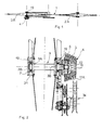
- the bicycle according to the invention comprises a frame 1, a front wheel 2A, a rear wheel 28, the hub 3 of which is provided with two flanges 3A receiving the spokes and receiving a freewheel device 4 constituted in particular by toothed rings. 5 and by a snap mechanism 4A
- the toothed rings 5 of the freewheel device 4 are mounted outside the frame of the bicycle.
- the hub has on either side of the flanges 3A as close as possible to these two rolling members 7 which cooperate in locking with the rear fork of the bicycle.
- the hub 3A has two bearing surfaces 3B.
- the hub 3 of the rear wheel is in one piece and is constituted by an axis equipped with the flanges 3A and has externally to the frame of the bicycle an extra length 6 to which is fixed the freewheel device.
- the extra length is provided beyond one of the bearing surfaces 3B of the hub.
- the extra length 6 receives an adapter nose 11 or spacer on which the freewheel device is screwed (fig.2).
- This generally cylindrical adapter nose has a thread along its axis to be screwed onto the threaded end of the extra length 6.
- the adapter nose has a threaded seat 11A onto which the freewheel device is screwed. has for this purpose a threaded orifice 12.
- the adapter nose 11 allows the mounting on the hub 3 of freewheel devices of the trade, the dia meter of the orifice 12 as well as the pitch being standardized.
- the hub 3 of the rear wheel consists of a cylindrical tubular element 8 provided with two flanges 3A and the rolling members 7 and by a shaft 9 mounted in the tubular element and coping with the latter via the snap mechanism 4A (shown diagrammatically) of the freewheel device.
- the shaft is extended axially, outside the frame and the tubular element by the extra length 6 which receives the toothed crowns 5 in fixation.
- the shaft 9 is carried in the tubular element 8 by two bearings 10.
- the latching mechanism 4A known per se is arranged around the shaft 9 between the bearings 10.
- the frame 1 of a bicycle provided with a freewheel device mounted on the outside is advantageously provided with a rear fork (13) the tubes of which are arranged in two parallel planes, that is to say that the two tubes 14 starting from the nut 15 of the bottom bracket are parallel to each other and that the two tubes 16 starting from the collar 17 saddle support are parallel to each other from the spacer 18 brake holder , each tube 14 being connected to a tube 16.
- the rear fork of the latter may be narrow, which will improve the aerodynamic qualities.
- tubes 14 of the rear fork are less subject to the effects of bending forces and can therefore be of smaller cross section, which reduces the weight of the bicycle.
- the rear fork of the bicycle is fitted with two cages 19 in each of which one of the rolling members 7 is blocked.
- the front fork of the bicycle is also equipped with two cages 19, the hub of the front wheel 2A on either side of the flanges 3A, being also equipped with rolling members 7.
- the cages 19 described above may also be mounted on the rear fork of a bicycle receiving the freewheeling device inside the frame. Such a configuration is shown in FIG. 6.
- the hub 3 is in one piece and also consists of an axis 3 equipped with two flanges 3A.
- This hub is also equipped with an extra length 6 to receive the freewheel device 4 inside the frame. At each end, this hub has two bearing surfaces 7. These bearings engage in the cages 19 of the rear fork.
- the cages 19 of the rear fork of a bicycle fitted with a free wheel device outside the frame are each fixed at the end of a tube 16 and of a tube 14.
- the cages 19 equipping the front fork are each fixed at the end of one of the tubes constituting this fork.
- Each cage 19 constituted for example by a disk-shaped wall has, coaxially to the axis of rotation of the wheel, a housing 20 open towards the inside of the frame in which the corresponding rolling member 7 is mounted, is provided with a means for blocking the rolling member 7 in the housing 20 and has a groove 21 radial to the housing 20 opening into the latter and at the peripheral edge, the width of this groove being at least equal to the outside diameter of the member bearing 7 so that the latter can be introduced radially into the housing 20 by passing through the groove 21.
- the groove 21 at the peripheral edge of the cage has chamfers 22 to facilitate the introduction of the rolling members 7.
- the grooves 21 of the cages 19 of the rear fork are oriented more towards the rear of the bicycle so that under the combined effect of the weight of the cyclist and the tensile force of the chain on the hub, the blocking of the rolling members in their housing 20 is reinforced.
- each cage 19 of the front fork develops under the housing 20 and is oriented towards the ground and slightly towards the front of the bicycle always to reinforce the locking of the bearings in the cages.
- the cage 19 disposed near these crowns has a slot 23 formed in the bottom of the groove 21 and of the housing 20. This slot has a width equal to or greater than the diameter of the extra length 6.
- each cage 19 is constituted by a bore with a diameter equal to the outside diameter of the rolling member 7 and the width of the groove 21 is equal to the diameter of the bore.
- the means for blocking the rolling members 7 in their cage 19, is constituted by a cylindrical cavity 24 of diameter equal to the outside diameter of the bearing 7 formed coaxially with the bore 20 in the bottom of the latter, said imprint was of shallower depth, for example 1 mm and being intended to receive the bearing.
- the normal distance between the two bottoms of the grooves 14 of the cages 19 of the same fork is less than the distance outside the bearing 7 of the corresponding hub.
- non-bearing distance means the normal distance measured between the bearings 7 increased by the thickness of the latter.
- the normal distance between the two bottoms of the imprints of the cages 19 of the same fork is equal to the distance without bearing.
- the hub by the rolling members 7, is pinched in the imprints 24 of the cages 19.
- each groove 21 has a chamfer at the level of the cavity 24.
- the means for locking the bearing in the housing 20 is constituted by a removable pin 25 disposed transversely in the groove 21 parallel to the bottom of the latter.
- This pin 25 engages at its ends in two orifices made in the pledge 19.
- the pin 25 is constituted by a screw. It is obvious that this pin can be formed by any other suitable member.
- the means for blocking the bearing in the housing 20 of the cag " consists of a pressure screw 26 engaged in a tapped orifice of which the axis is parallel to the bottom of the housing 20. This orifice opens into the said housing.
- the pressure screw 26 is brought into pressure against the bearing 7.
- the means for blocking the bearing in the housing 20 is constituted by a flange 27, shaped in an arc of circumference, brought to bear against the bearing 7.
- This flange in combination with the housing 20 of the cage 19 defines a cylindrical space in which the bearing is trapped.
- the flange is articulated at its ends to the cage 19 and cooperates at its other end with an elastic member 28 for example a clip which keeps it in abutment against the bearing.
- each cage 19 is equipped with a stop 29 which opposes the axial movement of the bearing relative to its housing ( Figure 12).
- the stop 29 is formed on the side of the cage facing the flanges 3A, is arranged opposite the housing 20 and is spaced from the bottom of the housing by a value equal to or slightly greater than the thickness of the bearing. This stop coming to bear against the bearing 7 opposes the spacing of the cages 19 as long as the wheel is in place in the fork.
- the hub of the front wheel and the hub of the rear wheel are equipped with a means opposing an excessive axial movement of the cages with respect to the bearing.
- the hubs are extended at at least one of their ends by a cylindrical portion 36, of smaller diameter than the axis making them up, terminated by a cylindrical button (31), the diameter of this button being larger. than that of the said portion.
- the corresponding cage 19 is provided with a slot 32 formed in the bottom of the groove 21 and in the bottom of the housing 20.
- This slot is very slightly greater than the diameter of the cylindrical portion 30 and is less than the diameter of the button 31.
- the button 31 is moved away from the cage 2 to avoid any friction problem. It should also be noted that the button 31 makes it easier to remove the wheel.
- the cage 19 which is on the side of the crowns 5 is provided with a lug 33 for fixing the derailleur 34.
Landscapes
- Engineering & Computer Science (AREA)
- Mechanical Engineering (AREA)
- Automatic Cycles, And Cycles In General (AREA)
- Motorcycle And Bicycle Frame (AREA)
- Axle Suspensions And Sidecars For Cycles (AREA)
- Steering Devices For Bicycles And Motorcycles (AREA)
- Artificial Filaments (AREA)
- Lubricants (AREA)
- Rolling Contact Bearings (AREA)
Priority Applications (3)
| Application Number | Priority Date | Filing Date | Title |
|---|---|---|---|
| AT86450002T ATE71335T1 (de) | 1985-01-11 | 1986-01-10 | Fahrrad. |
| PCT/FR1986/000446 WO1987004129A1 (fr) | 1986-01-10 | 1986-12-24 | Bicyclette perfectionnee |
| AU68401/87A AU6840187A (en) | 1986-01-10 | 1986-12-24 | Improved bicycle |
Applications Claiming Priority (4)
| Application Number | Priority Date | Filing Date | Title |
|---|---|---|---|
| FR858519460A FR2592353B1 (fr) | 1985-01-11 | 1985-01-11 | Bicyclette avec roue libre exterieure au cable. |
| FR8500674 | 1985-01-11 | ||
| FR8519460 | 1985-01-11 | ||
| FR8500674A FR2581954B1 (fr) | 1985-01-11 | 1985-01-11 | Moyeu pour roue de bicyclette a blocage dans des empreintes de la fourche et bicyclettes dont les roues sont equipees d'un tel moyeu |
Publications (3)
| Publication Number | Publication Date |
|---|---|
| EP0191710A2 true EP0191710A2 (de) | 1986-08-20 |
| EP0191710A3 EP0191710A3 (en) | 1987-07-01 |
| EP0191710B1 EP0191710B1 (de) | 1992-01-08 |
Family
ID=26224339
Family Applications (1)
| Application Number | Title | Priority Date | Filing Date |
|---|---|---|---|
| EP86450002A Expired - Lifetime EP0191710B1 (de) | 1985-01-11 | 1986-01-10 | Fahrrad |
Country Status (5)
| Country | Link |
|---|---|
| EP (1) | EP0191710B1 (de) |
| AT (1) | ATE71335T1 (de) |
| DE (1) | DE3683303D1 (de) |
| ES (1) | ES8707695A1 (de) |
| FR (1) | FR2592353B1 (de) |
Cited By (14)
| Publication number | Priority date | Publication date | Assignee | Title |
|---|---|---|---|---|
| WO1992001573A1 (en) * | 1990-07-23 | 1992-02-06 | E.I. Du Pont De Nemours And Company | Vehicle wheel |
| WO1997002149A1 (fr) * | 1995-06-30 | 1997-01-23 | Etablissement Bollini Batiment Et Industrie | Dispositif d'entrainement a roue libre, notamment pour une bicyclette |
| GB2392140A (en) * | 2002-08-23 | 2004-02-25 | Kenneth William Baldwin | Mounting of cycle wheel between fork legs |
| FR2894928A1 (fr) * | 2005-12-21 | 2007-06-22 | Cycles Pierre Soc Par Actions | Velo pliable articule |
| US7396304B2 (en) * | 2004-09-01 | 2008-07-08 | Shimano Inc. | Bicycle rear derailleur |
| WO2011056084A1 (en) * | 2009-11-09 | 2011-05-12 | Zielinski Grzegorz | Bicycle transmission system |
| US7963870B2 (en) | 2008-05-01 | 2011-06-21 | Shimano Inc. | Bicycle rear derailleur |
| FR2989660A1 (fr) * | 2012-04-19 | 2013-10-25 | Mavic Sas | Moyeu pour roue de cycle et roue de cycle comprenant un tel moyeu |
| WO2018011709A1 (en) * | 2016-07-11 | 2018-01-18 | Mariusz Kozak | Vehicle wheel axle |
| US11208171B2 (en) * | 2017-09-21 | 2021-12-28 | Veselin Mandaric | Drive assembly for a bicycle |
| US11975802B1 (en) | 2023-09-05 | 2024-05-07 | Red Star Holdings, Llc | Bicycle hub system, method and device including an interchangeable rear hub with a direct mount derailleur |
| US12059924B1 (en) | 2023-09-05 | 2024-08-13 | Red Star Holdings, Llc | Bicycle hub system, method and device including a front hub locking mechanism |
| US12059923B1 (en) | 2023-09-05 | 2024-08-13 | Red Star Holdings, Llc | Bicycle hub system, method and device including a rear hub locking mechanism |
| US12059922B1 (en) | 2023-09-05 | 2024-08-13 | Red Star Holdings, Llc | Bicycle hub system, method and device including an interchangeable hub locking mechanism |
Family Cites Families (4)
| Publication number | Priority date | Publication date | Assignee | Title |
|---|---|---|---|---|
| US2018973A (en) * | 1935-04-19 | 1935-10-29 | Matthews Mfg Company | Front fork for vehicles |
| FR1388952A (fr) * | 1963-12-24 | 1965-02-12 | Perfectionnements aux moyeux et aux dispositifs d'entraînement pour roues de cycles | |
| FR2340830A1 (fr) * | 1976-02-16 | 1977-09-09 | Pelissier Sarl Anc Ets Cl | Moyeu a roulements perfectionne pour cycles et vehicules |
| US4102215A (en) * | 1976-05-19 | 1978-07-25 | Shimano Industrial Company Limited | Multi-speed freewheel for a bicycle |
-
1985
- 1985-01-11 FR FR858519460A patent/FR2592353B1/fr not_active Expired - Lifetime
-
1986
- 1986-01-10 EP EP86450002A patent/EP0191710B1/de not_active Expired - Lifetime
- 1986-01-10 DE DE8686450002T patent/DE3683303D1/de not_active Expired - Lifetime
- 1986-01-10 AT AT86450002T patent/ATE71335T1/de not_active IP Right Cessation
- 1986-01-10 ES ES550794A patent/ES8707695A1/es not_active Expired
Cited By (20)
| Publication number | Priority date | Publication date | Assignee | Title |
|---|---|---|---|---|
| WO1992001573A1 (en) * | 1990-07-23 | 1992-02-06 | E.I. Du Pont De Nemours And Company | Vehicle wheel |
| WO1997002149A1 (fr) * | 1995-06-30 | 1997-01-23 | Etablissement Bollini Batiment Et Industrie | Dispositif d'entrainement a roue libre, notamment pour une bicyclette |
| US6059305A (en) * | 1995-06-30 | 2000-05-09 | Jean Bollini | Freewheel drive device, particularly for a bicycle |
| GB2392140A (en) * | 2002-08-23 | 2004-02-25 | Kenneth William Baldwin | Mounting of cycle wheel between fork legs |
| GB2392140B (en) * | 2002-08-23 | 2004-06-30 | Kenneth William Baldwin | Cycle wheel mounting components thereof and cycle including wheel mounting |
| US7396304B2 (en) * | 2004-09-01 | 2008-07-08 | Shimano Inc. | Bicycle rear derailleur |
| FR2894928A1 (fr) * | 2005-12-21 | 2007-06-22 | Cycles Pierre Soc Par Actions | Velo pliable articule |
| EP1803634A1 (de) * | 2005-12-21 | 2007-07-04 | Cycles Lapierre | Zusammenklappbares Fahrrad mit einem am Tretkurbelkasten positionierten Gelenk |
| US7963870B2 (en) | 2008-05-01 | 2011-06-21 | Shimano Inc. | Bicycle rear derailleur |
| WO2011056084A1 (en) * | 2009-11-09 | 2011-05-12 | Zielinski Grzegorz | Bicycle transmission system |
| FR2989660A1 (fr) * | 2012-04-19 | 2013-10-25 | Mavic Sas | Moyeu pour roue de cycle et roue de cycle comprenant un tel moyeu |
| WO2018011709A1 (en) * | 2016-07-11 | 2018-01-18 | Mariusz Kozak | Vehicle wheel axle |
| CN110023183A (zh) * | 2016-07-11 | 2019-07-16 | 马里乌什·科扎克 | 车辆轮轴 |
| US11077912B2 (en) | 2016-07-11 | 2021-08-03 | Mariusz Kozak | Vehicle wheel axle |
| CN110023183B (zh) * | 2016-07-11 | 2021-11-09 | 马里乌什·科扎克 | 车辆轮轴 |
| US11208171B2 (en) * | 2017-09-21 | 2021-12-28 | Veselin Mandaric | Drive assembly for a bicycle |
| US11975802B1 (en) | 2023-09-05 | 2024-05-07 | Red Star Holdings, Llc | Bicycle hub system, method and device including an interchangeable rear hub with a direct mount derailleur |
| US12059924B1 (en) | 2023-09-05 | 2024-08-13 | Red Star Holdings, Llc | Bicycle hub system, method and device including a front hub locking mechanism |
| US12059923B1 (en) | 2023-09-05 | 2024-08-13 | Red Star Holdings, Llc | Bicycle hub system, method and device including a rear hub locking mechanism |
| US12059922B1 (en) | 2023-09-05 | 2024-08-13 | Red Star Holdings, Llc | Bicycle hub system, method and device including an interchangeable hub locking mechanism |
Also Published As
| Publication number | Publication date |
|---|---|
| FR2592353B1 (fr) | 1991-05-10 |
| FR2592353A1 (fr) | 1987-07-03 |
| ES550794A0 (es) | 1987-08-16 |
| ATE71335T1 (de) | 1992-01-15 |
| EP0191710A3 (en) | 1987-07-01 |
| ES8707695A1 (es) | 1987-08-16 |
| EP0191710B1 (de) | 1992-01-08 |
| DE3683303D1 (de) | 1992-02-20 |
Similar Documents
| Publication | Publication Date | Title |
|---|---|---|
| EP0191710B1 (de) | Fahrrad | |
| EP0890505B1 (de) | Zweirad-Radnaben-Montagevorrichtung | |
| EP3187402B1 (de) | Sattelträger einer scheibenbremse für ein fahrrad oder ähnlich | |
| EP4182652A1 (de) | Fahrradantriebsvorrichtung mit drehmomentsensor | |
| FR2640222A1 (fr) | Mecanisme d'entrainement a axe unique | |
| CH676086A5 (de) | ||
| FR2533283A1 (fr) | Moyeu a roue libre pour bicyclette | |
| FR2521656A1 (fr) | Dispositif de fixation des deux ailes d'une chape de derailleur de pedalier pour bicyclette | |
| EP3187406A1 (de) | Lasche eines hinteren arms eines fahrrads oder ähnlichem, und fahrrad, das eine solche lasche eines hinteren arms umfasst | |
| FR2921630A1 (fr) | Pedalier multi plateaux a roue libre integree | |
| WO1987004129A1 (fr) | Bicyclette perfectionnee | |
| EP2879943B1 (de) | In ein steckenpferd umwandelbares fahrrad | |
| WO1991012167A1 (fr) | Dispositif de propulsion pour bicyclette a deux roues motrices et bicyclette munie de ce dispositif | |
| FR2843364A1 (fr) | Pedalier pour cycle avec un bras de levier optimise | |
| FR2720367A1 (fr) | Dispositif de roue libre compound résistant aux chocs pour bicyclettes. | |
| FR2822433A1 (fr) | Pedale de bicyclette a fixation de securite | |
| CA2457257C (fr) | Dispositif de transfert perfectionne pour systeme de transport, tel que trottoir roulant | |
| EP0983186B1 (de) | Fahrradpedal mit kraftübersetzungsgetriebe | |
| EP0284535A1 (de) | Fahrrad, dessen Räder nur an einer Seite des Rahmens befestigt sind | |
| FR2792250A1 (fr) | Roue de bicyclette a rayons | |
| FR2616384A1 (fr) | Roue a rayons, en particulier pour bicyclettes, velomoteurs, cyclomoteurs, vehicules automobiles et autres | |
| FR2550752A1 (fr) | Pedalier a developpement variable | |
| FR2543098A1 (fr) | Vehicule propulse par un systeme de pedales | |
| EP1762658A1 (de) | Vorrichtung zur Beschränkung des Zugriffs eines Motorrads in eine Zone | |
| BE855828A (fr) | Frein de bicyclette actionne par les petales |
Legal Events
| Date | Code | Title | Description |
|---|---|---|---|
| PUAI | Public reference made under article 153(3) epc to a published international application that has entered the european phase |
Free format text: ORIGINAL CODE: 0009012 |
|
| AK | Designated contracting states |
Kind code of ref document: A2 Designated state(s): AT BE CH DE FR GB IT LI LU NL SE |
|
| PUAL | Search report despatched |
Free format text: ORIGINAL CODE: 0009013 |
|
| AK | Designated contracting states |
Kind code of ref document: A3 Designated state(s): AT BE CH DE FR GB IT LI LU NL SE |
|
| 17P | Request for examination filed |
Effective date: 19871231 |
|
| RAP3 | Party data changed (applicant data changed or rights of an application transferred) |
Owner name: BARRAU, CARMEN Owner name: ALVAREZ, MICHEL |
|
| 17Q | First examination report despatched |
Effective date: 19890525 |
|
| RAP3 | Party data changed (applicant data changed or rights of an application transferred) |
Owner name: BARRAU, CARMEN Owner name: ALVAREZ, MICHEL |
|
| GRAA | (expected) grant |
Free format text: ORIGINAL CODE: 0009210 |
|
| AK | Designated contracting states |
Kind code of ref document: B1 Designated state(s): AT BE CH DE FR GB IT LI LU NL SE |
|
| PG25 | Lapsed in a contracting state [announced via postgrant information from national office to epo] |
Ref country code: IT Free format text: LAPSE BECAUSE OF FAILURE TO SUBMIT A TRANSLATION OF THE DESCRIPTION OR TO PAY THE FEE WITHIN THE PRE;WARNING: LAPSES OF ITALIAN PATENTS WITH EFFECTIVE DATE BEFORE 2007 MAY HAVE OCCURRED AT ANY TIME BEFORE 2007. THE CORRECT EFFECTIVE DATE MAY BE DIFFERENT FROM THE ONE RECORDED.SCRIBED TIME-LIMIT Effective date: 19920108 Ref country code: AT Effective date: 19920108 Ref country code: NL Effective date: 19920108 Ref country code: GB Effective date: 19920108 Ref country code: SE Effective date: 19920108 |
|
| REF | Corresponds to: |
Ref document number: 71335 Country of ref document: AT Date of ref document: 19920115 Kind code of ref document: T |
|
| PG25 | Lapsed in a contracting state [announced via postgrant information from national office to epo] |
Ref country code: LI Effective date: 19920131 Ref country code: BE Effective date: 19920131 Ref country code: LU Free format text: LAPSE BECAUSE OF NON-PAYMENT OF DUE FEES Effective date: 19920131 Ref country code: CH Effective date: 19920131 |
|
| REF | Corresponds to: |
Ref document number: 3683303 Country of ref document: DE Date of ref document: 19920220 |
|
| NLV1 | Nl: lapsed or annulled due to failure to fulfill the requirements of art. 29p and 29m of the patents act | ||
| GBV | Gb: ep patent (uk) treated as always having been void in accordance with gb section 77(7)/1977 [no translation filed] | ||
| BERE | Be: lapsed |
Owner name: ALVAREZ MICHEL Effective date: 19920131 Owner name: BARRAU CARMEN Effective date: 19920131 |
|
| REG | Reference to a national code |
Ref country code: CH Ref legal event code: PL |
|
| PG25 | Lapsed in a contracting state [announced via postgrant information from national office to epo] |
Ref country code: DE Effective date: 19921001 |
|
| PLBE | No opposition filed within time limit |
Free format text: ORIGINAL CODE: 0009261 |
|
| STAA | Information on the status of an ep patent application or granted ep patent |
Free format text: STATUS: NO OPPOSITION FILED WITHIN TIME LIMIT |
|
| PG25 | Lapsed in a contracting state [announced via postgrant information from national office to epo] |
Ref country code: FR Effective date: 19921130 |
|
| 26N | No opposition filed | ||
| REG | Reference to a national code |
Ref country code: FR Ref legal event code: ST |
|
| PG25 | Lapsed in a contracting state [announced via postgrant information from national office to epo] |
Ref country code: FR Effective date: 19920131 |