EP0191653B1 - Appareil de mesure de la résistance au choc - Google Patents
Appareil de mesure de la résistance au choc Download PDFInfo
- Publication number
- EP0191653B1 EP0191653B1 EP86400009A EP86400009A EP0191653B1 EP 0191653 B1 EP0191653 B1 EP 0191653B1 EP 86400009 A EP86400009 A EP 86400009A EP 86400009 A EP86400009 A EP 86400009A EP 0191653 B1 EP0191653 B1 EP 0191653B1
- Authority
- EP
- European Patent Office
- Prior art keywords
- anvil
- mass
- opening
- male part
- test
- Prior art date
- Legal status (The legal status is an assumption and is not a legal conclusion. Google has not performed a legal analysis and makes no representation as to the accuracy of the status listed.)
- Expired
Links
Images
Classifications
-
- G—PHYSICS
- G01—MEASURING; TESTING
- G01N—INVESTIGATING OR ANALYSING MATERIALS BY DETERMINING THEIR CHEMICAL OR PHYSICAL PROPERTIES
- G01N3/00—Investigating strength properties of solid materials by application of mechanical stress
- G01N3/30—Investigating strength properties of solid materials by application of mechanical stress by applying a single impulsive force, e.g. by falling weight
- G01N3/303—Investigating strength properties of solid materials by application of mechanical stress by applying a single impulsive force, e.g. by falling weight generated only by free-falling weight
-
- G—PHYSICS
- G01—MEASURING; TESTING
- G01N—INVESTIGATING OR ANALYSING MATERIALS BY DETERMINING THEIR CHEMICAL OR PHYSICAL PROPERTIES
- G01N2203/00—Investigating strength properties of solid materials by application of mechanical stress
- G01N2203/02—Details not specific for a particular testing method
- G01N2203/022—Environment of the test
- G01N2203/0222—Temperature
- G01N2203/0228—Low temperature; Cooling means
Definitions
- the present invention relates to an apparatus for measuring impact resistance and more particularly to a system for bringing the test pieces to temperature, prior to measurement, adapted to the apparatus.
- the impact resistance measuring devices essentially consist of an anvil, hollow in the axis of the fall of the mass, and possibly jaws serving to fix the test tube at the anvil.
- anvil essentially consist of an anvil, hollow in the axis of the fall of the mass, and possibly jaws serving to fix the test tube at the anvil.
- jaws serving to fix the test tube at the anvil.
- the present invention consists of an apparatus making it possible to cool only the test piece. Briefly, a thermal means coming into contact with the test piece is introduced into the hollow part of the anvil; when the latter is at the right temperature, the thermal means is removed while, substantially simultaneously, by means of an appropriate servo means, a moving mass comes into contact with the test piece. Given the mobility of the thermal means, the device is not exclusively reserved for cold shock measurements.
- the appended figure illustrates the description of the device.
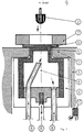
- the apparatus consisting of an anvil 1 pierced right through the axis of the fall of a mass 2 and preferably fixed on a frame 3 and of thermal means 4 is characterized in that the thermal means, independent of the anvil and movable with respect to it, has a male part 5, the perimeter of which preferably corresponds substantially to that of the pierced part of the anvil while leaving this male part free in this female part of the anvil , and the surface of which comes at least vertically above the surface of the anvil to come into contact with the test piece 6 in the heat exchange phase. It is not excluded to provide jaws 7 allowing the specimen to be immobilized on the anvil.
- the thermal means 4 is usually a reservoir in which, for example, a liquid circulates via the tubes 8, or containing a means allowing the heat exchange. It can simply be envisaged, in the case where it is desired to reheat the test piece, to place a heating resistor in the male part (5). It may also, for reasons of economy, be envisaged to insulate 9 the thermal means 4.
- the advantage of the apparatus lies in the mobility of the thermal means 4.
- the thermal means When the test piece is at the desired temperature, the thermal means is allowed to escape while releasing the mass 2 on the test piece.
- the reliability of the measurement lies in the minimum time difference which must exist between the break in contact between the test piece and the thermal means, and the moment of impact of the mass with the test piece.
- An effective means for limiting this time difference as much as possible consists in controlling the release of the mass 2 to the exhaust of the thermal means 4.
- This control means may consist in switching on, by contact with the thermal means, a system for releasing the mass located on the exhaust path of said thermal means.
- the contact 10 can for example be a switch controlling an electromagnet system or even a pneumatic system.
Description
- La présente invention concerne un appareil de mesure de la résistance au choc et plus particulièrement un système de mise en température des éprouvettes, préalablement à la mesure, adapté sur l'appareil.
- De façon simplifiée, les appareils de mesure de résistance au choc, plus particulièrement adaptés pour contrôler les matières plastiques, sont essentiellement constitués d'une enclume, creuse dans l'axe de la chute de la masse, et éventuellement de mors servant à fixer l'éprouvette à l'enclume. Bien entendu sont également additionnés des moyens de mesure et d'enregistrement des résultats qui ne concernent pas directement l'invention.
- Dans le cas des mesures à froid, selon l'art antérieur tel que par exemple le US-A-4 405 243, pour refroidir l'éprouvette il est nécessaire de la placer avec l'enclume et les mors de fixation dans une enceinte refroidie. Lorsque l'éprouvette a atteint la température souhaitée l'ensemble est retiré de l'enceinte pour que l'éprouvette soit immédiatement soumise au choc. Un tel système nécessite un appareillage de refroidissement volumineux; de plus la méthode est lente et onéreuse, inconvénients dûs en particulier à la perte de temps pour le refroidissement de l'ensemble de fixation de l'éprouvette et à une perte d'énergie pour ce même refroidissement.
- La présente invention consiste en un appareillage permettant de ne refroidir que l'éprouvette. Succinctement, on introduit dans la partie creuse de l'enclume un moyen thermique venant en contact avec l'éprouvette; lorsque cette dernière se trouve à la bonne température, le moyen thermique est retiré tandis que, sensiblement simultanément, grâce à un moyen d'asservissement approprié, une masse en mouvement entre en contact avec l'éprouvette. Compte tenu de la mobilité du moyen thermique, l'appareil n'est pas exclusivement reservé aux mesures de choc à froid.
- La figure annexée permet d'illustrer la description de l'appareil. L'appareil constitué d'une enclume 1 percée de part en part dans l'axe de la chute d'une masse 2 et de préférence fixée sur un bâti 3 et d'un moyen thermique 4 est caractérisé en ce que le moyen thermique, indépendant de l'enclume et mobile par rapport à elle, possède une partie mâle 5, dont le périmètre correspond de préférence sensiblement à celle de la partie percée de l'enclume tout en laissant libre cette partie mâle dans cette partie femelle de l'enclume, et dont la surface vient au minimum à l'aplomb de la surface de l'enclume pour entrer en contact avec l'éprouvette 6 dans la phase d'échange thermique. Il n'est pas exclu de prévoir des mors 7 permettant d'immobiliser l'éprouvette sur l'enclume. Le moyen thermique 4 est habituellement un réservoir dans lequel, par exemple, circule un liquide par l'intermédiaire des tubes 8, ou contenant un moyen permettant l'échange thermique. Il peut tout simplement être envisagé, dans le cas où on souhaite réchauffer l'éprouvette, de placer une résistance chauffante dans la partie mâle (5). Il peut également, par mesure d'économie, être envisagé decalorifuger 9 le moyen thermique 4.
- L'intérêt de l'appareillage se trouve dans la mobilité du moyen thermique 4. Lorsque l'éprouvette se trouve à la température souhaitée on laisse s'échapper le moyen thermique tout en lâchant la masse 2 sur l'éprouvette. Bien entendu la fiabilité de la mesure réside dans l'écart de temps minimum qui doit exister entre la rupture du contact entre l'éprouvette et le moyen thermique, et le moment d'impact de la masse avec l'éprouvette. Un moyen efficace pour limiter au maximum cet écart de temps consiste à asservir la libération de la masse 2 à l'échappement du moyen thermique 4. Ce moyen d'asservissement peut consister à enclancher, par contact du moyen thermique, un système de libération de la masse situé sur le parcours d'échappement dudit moyen thermique.
- Un exemple concret, mais non limitatif, peut illustrer l'invention. Il es possible de monter le moyen thermique sur un système hydraulique, tel un vérin. Lors de la libération du piston 11 du vérin, le moyen thermique chute brutalement; sur le parcours de la chute il rencontre le contact 10 qui déclanche la libération de la masse 2. Le contact 10 peut par exemple être un interrupteur commandant un système d'électro-aimant ou encore un système pneumatique.
Claims (6)
Priority Applications (1)
| Application Number | Priority Date | Filing Date | Title |
|---|---|---|---|
| AT86400009T ATE45038T1 (de) | 1985-01-14 | 1986-01-03 | Stosspruefgeraet. |
Applications Claiming Priority (2)
| Application Number | Priority Date | Filing Date | Title |
|---|---|---|---|
| FR8500426A FR2576101B1 (fr) | 1985-01-14 | 1985-01-14 | Appareil de mesure de la resistance au choc |
| FR8500426 | 1985-01-14 |
Publications (2)
| Publication Number | Publication Date |
|---|---|
| EP0191653A1 EP0191653A1 (fr) | 1986-08-20 |
| EP0191653B1 true EP0191653B1 (fr) | 1989-07-26 |
Family
ID=9315225
Family Applications (1)
| Application Number | Title | Priority Date | Filing Date |
|---|---|---|---|
| EP86400009A Expired EP0191653B1 (fr) | 1985-01-14 | 1986-01-03 | Appareil de mesure de la résistance au choc |
Country Status (6)
| Country | Link |
|---|---|
| US (1) | US4674318A (fr) |
| EP (1) | EP0191653B1 (fr) |
| JP (1) | JPS62282240A (fr) |
| AT (1) | ATE45038T1 (fr) |
| DE (1) | DE3664685D1 (fr) |
| FR (1) | FR2576101B1 (fr) |
Families Citing this family (3)
| Publication number | Priority date | Publication date | Assignee | Title |
|---|---|---|---|---|
| US5092179A (en) * | 1991-03-08 | 1992-03-03 | Duffers Scientific, Inc. | Dynamic material testing system having independent control over specimen deformation and strain rate and a method for use therein |
| US5686652A (en) * | 1996-09-09 | 1997-11-11 | Pfund; Bruce | Portable test hammer apparatus |
| CN108169038B (zh) * | 2018-01-11 | 2024-01-19 | 山东建筑大学 | 一种大直径钻头冲击破岩检测装置 |
Family Cites Families (9)
| Publication number | Priority date | Publication date | Assignee | Title |
|---|---|---|---|---|
| DE1075868B (de) * | 1960-02-18 | Alfred J Amsler S. Co Schaffhausen (Schweiz), Vextr Di K Griesmg Pat -Anw Honebach bei Bebra | Pendelschlagwerk | |
| GB666058A (en) * | 1949-09-21 | 1952-02-06 | Meehanite Metal Corp | Apparatus for testing moulding sand |
| US2748596A (en) * | 1951-11-19 | 1956-06-05 | American Viscose Corp | Rupture tester |
| US2892342A (en) * | 1954-12-30 | 1959-06-30 | Gen Electric | Plastic testing machine |
| US3056279A (en) * | 1959-10-22 | 1962-10-02 | Thiokol Chemical Corp | Apparatus for impact testing |
| DE1900802U (de) * | 1964-05-12 | 1964-09-17 | Hoechst Ag | Geraet zur pruefung des stossverhaltens von folien, geweben und aehnlichen flaechenhaften gebilden. |
| FR2195343A5 (fr) * | 1972-08-02 | 1974-03-01 | Comp Generale Electricite | |
| US4405243A (en) * | 1980-12-26 | 1983-09-20 | Hoxan Corporation | Cryogenic impact testing method and machine |
| JPS57163843A (en) * | 1981-04-02 | 1982-10-08 | Toshiba Corp | Testing apparatus for high temperature impact fatigue |
-
1985
- 1985-01-14 FR FR8500426A patent/FR2576101B1/fr not_active Expired
- 1985-12-17 US US06/809,735 patent/US4674318A/en not_active Expired - Fee Related
-
1986
- 1986-01-03 EP EP86400009A patent/EP0191653B1/fr not_active Expired
- 1986-01-03 DE DE8686400009T patent/DE3664685D1/de not_active Expired
- 1986-01-03 AT AT86400009T patent/ATE45038T1/de not_active IP Right Cessation
- 1986-01-14 JP JP61006175A patent/JPS62282240A/ja active Granted
Also Published As
| Publication number | Publication date |
|---|---|
| ATE45038T1 (de) | 1989-08-15 |
| FR2576101A1 (fr) | 1986-07-18 |
| JPS62282240A (ja) | 1987-12-08 |
| EP0191653A1 (fr) | 1986-08-20 |
| JPH0343578B2 (fr) | 1991-07-03 |
| FR2576101B1 (fr) | 1987-02-06 |
| DE3664685D1 (en) | 1989-08-31 |
| US4674318A (en) | 1987-06-23 |
Similar Documents
| Publication | Publication Date | Title |
|---|---|---|
| US4474015A (en) | Method of and apparatus for the controlled cooling of a product | |
| US6581438B1 (en) | Capillary test specimen, system, and methods for in-situ visualization of capillary flow and fillet formation | |
| EP0349042A3 (fr) | Système de contrôle automatique de circuits intégrés | |
| US3315529A (en) | Method and apparatus for taking samples from melts in order to obtain the gases evolved during solidification | |
| EP0191653B1 (fr) | Appareil de mesure de la résistance au choc | |
| US3913404A (en) | Sampling device | |
| US3936587A (en) | Electrode construction for resistance heating furnace | |
| US4941364A (en) | Holder for molten metal sampling device | |
| US5084229A (en) | Critical heat flux test apparatus | |
| JP2002181671A (ja) | 試料導入アセンブリ | |
| US3496760A (en) | Method and apparatus for determining the pour point of liquids | |
| EP0397936A1 (fr) | Détermination de la température à laquelle une substance change d'état | |
| US4176956A (en) | Sample tube mounting structure for flameless atomic absorption spectroscopy | |
| CA2583853C (fr) | Methode et appareillage de controle de l'aptitude au brasage d'elements electriques | |
| JPS59202063A (ja) | 検査試料ろ過装置 | |
| US3507144A (en) | Gas content analysis with a metal levitation system | |
| JP2515573B2 (ja) | 試料凍結装置 | |
| KR960003191B1 (ko) | 산화물을 발생시키지 않는 샘플러 | |
| US4371262A (en) | Holder for absorption spectrometer atomizing furnace capsules | |
| CA2007179C (fr) | Support pour dispositif de prise d'echantillons de metal en fusion | |
| RU2121674C1 (ru) | Экстракционно-загрузочный узел прибора для определения содержания водорода в алюминии и его сплавах методом вакуум-нагрева | |
| US3765248A (en) | Molten metal sampler and method of use | |
| IE46941B1 (en) | Sample tube mounting | |
| US4322967A (en) | Method and apparatus for measuring optical coupling coefficients | |
| JPH0612960U (ja) | ピンサンプラ用ホルダ |
Legal Events
| Date | Code | Title | Description |
|---|---|---|---|
| PUAI | Public reference made under article 153(3) epc to a published international application that has entered the european phase |
Free format text: ORIGINAL CODE: 0009012 |
|
| 17P | Request for examination filed |
Effective date: 19860108 |
|
| AK | Designated contracting states |
Kind code of ref document: A1 Designated state(s): AT BE CH DE FR GB IT LI LU NL SE |
|
| 17Q | First examination report despatched |
Effective date: 19880407 |
|
| GRAA | (expected) grant |
Free format text: ORIGINAL CODE: 0009210 |
|
| AK | Designated contracting states |
Kind code of ref document: B1 Designated state(s): AT BE CH DE FR GB IT LI LU NL SE |
|
| REF | Corresponds to: |
Ref document number: 45038 Country of ref document: AT Date of ref document: 19890815 Kind code of ref document: T |
|
| ITF | It: translation for a ep patent filed |
Owner name: JACOBACCI & PERANI S.P.A. |
|
| GBT | Gb: translation of ep patent filed (gb section 77(6)(a)/1977) | ||
| REF | Corresponds to: |
Ref document number: 3664685 Country of ref document: DE Date of ref document: 19890831 |
|
| PLBE | No opposition filed within time limit |
Free format text: ORIGINAL CODE: 0009261 |
|
| STAA | Information on the status of an ep patent application or granted ep patent |
Free format text: STATUS: NO OPPOSITION FILED WITHIN TIME LIMIT |
|
| 26N | No opposition filed | ||
| ITTA | It: last paid annual fee | ||
| EPTA | Lu: last paid annual fee | ||
| PGFP | Annual fee paid to national office [announced via postgrant information from national office to epo] |
Ref country code: GB Payment date: 19941228 Year of fee payment: 10 |
|
| PGFP | Annual fee paid to national office [announced via postgrant information from national office to epo] |
Ref country code: FR Payment date: 19950110 Year of fee payment: 10 Ref country code: DE Payment date: 19950110 Year of fee payment: 10 |
|
| PGFP | Annual fee paid to national office [announced via postgrant information from national office to epo] |
Ref country code: AT Payment date: 19950111 Year of fee payment: 10 |
|
| PGFP | Annual fee paid to national office [announced via postgrant information from national office to epo] |
Ref country code: CH Payment date: 19950113 Year of fee payment: 10 |
|
| PGFP | Annual fee paid to national office [announced via postgrant information from national office to epo] |
Ref country code: SE Payment date: 19950118 Year of fee payment: 10 |
|
| EAL | Se: european patent in force in sweden |
Ref document number: 86400009.6 |
|
| PGFP | Annual fee paid to national office [announced via postgrant information from national office to epo] |
Ref country code: NL Payment date: 19950131 Year of fee payment: 10 |
|
| PGFP | Annual fee paid to national office [announced via postgrant information from national office to epo] |
Ref country code: LU Payment date: 19950201 Year of fee payment: 10 |
|
| PGFP | Annual fee paid to national office [announced via postgrant information from national office to epo] |
Ref country code: BE Payment date: 19950302 Year of fee payment: 10 |
|
| PG25 | Lapsed in a contracting state [announced via postgrant information from national office to epo] |
Ref country code: LU Free format text: LAPSE BECAUSE OF NON-PAYMENT OF DUE FEES Effective date: 19960103 Ref country code: GB Effective date: 19960103 Ref country code: AT Effective date: 19960103 |
|
| PG25 | Lapsed in a contracting state [announced via postgrant information from national office to epo] |
Ref country code: SE Effective date: 19960104 |
|
| PG25 | Lapsed in a contracting state [announced via postgrant information from national office to epo] |
Ref country code: LI Effective date: 19960131 Ref country code: CH Effective date: 19960131 Ref country code: BE Effective date: 19960131 |
|
| BERE | Be: lapsed |
Owner name: ATOCHEM Effective date: 19960131 |
|
| PG25 | Lapsed in a contracting state [announced via postgrant information from national office to epo] |
Ref country code: NL Effective date: 19960801 |
|
| GBPC | Gb: european patent ceased through non-payment of renewal fee |
Effective date: 19960103 |
|
| REG | Reference to a national code |
Ref country code: CH Ref legal event code: PL |
|
| PG25 | Lapsed in a contracting state [announced via postgrant information from national office to epo] |
Ref country code: FR Effective date: 19960930 |
|
| NLV4 | Nl: lapsed or anulled due to non-payment of the annual fee |
Effective date: 19960801 |
|
| PG25 | Lapsed in a contracting state [announced via postgrant information from national office to epo] |
Ref country code: DE Effective date: 19961001 |
|
| EUG | Se: european patent has lapsed |
Ref document number: 86400009.6 |
|
| REG | Reference to a national code |
Ref country code: FR Ref legal event code: ST |
|
| PG25 | Lapsed in a contracting state [announced via postgrant information from national office to epo] |
Ref country code: IT Free format text: LAPSE BECAUSE OF NON-PAYMENT OF DUE FEES;WARNING: LAPSES OF ITALIAN PATENTS WITH EFFECTIVE DATE BEFORE 2007 MAY HAVE OCCURRED AT ANY TIME BEFORE 2007. THE CORRECT EFFECTIVE DATE MAY BE DIFFERENT FROM THE ONE RECORDED. Effective date: 20050103 |