EP0190939B1 - High frequency attenuation cable and harness - Google Patents
High frequency attenuation cable and harness Download PDFInfo
- Publication number
- EP0190939B1 EP0190939B1 EP86300836A EP86300836A EP0190939B1 EP 0190939 B1 EP0190939 B1 EP 0190939B1 EP 86300836 A EP86300836 A EP 86300836A EP 86300836 A EP86300836 A EP 86300836A EP 0190939 B1 EP0190939 B1 EP 0190939B1
- Authority
- EP
- European Patent Office
- Prior art keywords
- high frequency
- cable
- dielectric constant
- layer
- conductor
- Prior art date
- Legal status (The legal status is an assumption and is not a legal conclusion. Google has not performed a legal analysis and makes no representation as to the accuracy of the status listed.)
- Expired - Lifetime
Links
Images


Classifications
-
- H—ELECTRICITY
- H01—ELECTRIC ELEMENTS
- H01B—CABLES; CONDUCTORS; INSULATORS; SELECTION OF MATERIALS FOR THEIR CONDUCTIVE, INSULATING OR DIELECTRIC PROPERTIES
- H01B11/00—Communication cables or conductors
- H01B11/02—Cables with twisted pairs or quads
- H01B11/06—Cables with twisted pairs or quads with means for reducing effects of electromagnetic or electrostatic disturbances, e.g. screens
-
- H—ELECTRICITY
- H01—ELECTRIC ELEMENTS
- H01B—CABLES; CONDUCTORS; INSULATORS; SELECTION OF MATERIALS FOR THEIR CONDUCTIVE, INSULATING OR DIELECTRIC PROPERTIES
- H01B11/00—Communication cables or conductors
- H01B11/02—Cables with twisted pairs or quads
- H01B11/12—Arrangements for exhibiting specific transmission characteristics
- H01B11/14—Continuously inductively loaded cables, e.g. Krarup cables
- H01B11/146—Continuously inductively loaded cables, e.g. Krarup cables using magnetically loaded coatings
Definitions
- This invention relates to a high frequency attenuation cable and to a high frequency attenuation cable harness.
- High frequency attenuation cables are well known.
- such cables include an absorption medium which filters out high frequency energy which could otherwise interfere with the operation of the cable.
- the effectiveness with which the high frequency energy is filtered out is referred to as the high frequency attenuation. The greater the attenuation, the higher the effectiveness.
- One aspect of this invention comprises a high frequency attenuation cable comprising a core comprising at least one conductor, each said conductor being surrounded by a layer of high dielectric constant material having a dielectric constant greater than about 4 when measured at 10 MHz and a volume resistivity of at least about 1013 ohm-cm; and a layer of high frequency absorption medium.
- the high dielectric constant material preferably also has a tensile strength of at least about 4,000 pounds per square inch (psi) (285 Kg/cm2). Additional layers of the absorption medium and/or the high dielectric material and/or a second dielectric material may also be present.
- the core is that portion of the cable which is surrounded by the electrically conductive shield and any outer or protective jacketing.
- Figure 1 is a cut-away side view of one embodiment of a cable construction according to the invention.
- Figure 2 is a cut-away side view of another embodiment of a cable construction according to the invention.
- Figure 3 is a cross-sectional view of one embodiment of a cable harness according to the invention.
- Figure 4 is a cross-sectional view of another embodiment of a cable harness according to the invention.
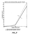
- Figures 5 and 6 are graphs of attenuation versus frequency for cable constructions according to the invention compared to cable constructions according to the prior art.
- the cable comprises a core which, in turn, comprises conductor 4, a layer of high frequency absorption medium 6 surrounding the conductor, and a layer of high dielectric constant material 8 surrounding the high frequency absorption medium.
- the cable may further comprise additional layers of absorption medium, high dielectric constant material, a second dielectric material and the like. Further the cable generally also is provided with an electrically conductive shield and a protective outer jacket.
- a layer of high dielectric constant material markedly increases the high frequency attenuation of the cable in the frequency range of 10 to 100 MHz.
- TEFZEL is a copolymer of ethylene and tetrafluoroethylene and is a product of E.I. duPont de Nemours, Wilmington, DE.
- TEFZEL is a copolymer of ethylene and tetrafluoroethylene and is a product of E.I. duPont de Nemours, Wilmington, DE.
- Both polyethylene and TEFZEL are materials having low dielectric constants ( ⁇ of about 2-3).
- prior art cables exhibit lower high frequency attenuation in the frequency range of 10-100 MHz than is desirable for certain uses.
- the high frequency absorption medium such as the well-known lossy materials disclosed in the Cornelius et al. references serves to allow the passage of low frequency energy but absorbs the high frequency energy.
- Lossy materials are also disclosed in Mayer, USP 3,309,633 and USP 3,191,132 which are incorporated herein by reference.
- a preferred lossy material for the present invention is ferrite-loaded polymer, for example, ferrite-loaded VITON® A (VITON A is a copolymer of vinylidene fluoride and hexafluoropropylene and is a product of E. I. Du Pont de Nemours, Wilmington, DE).
- FIG. 2 there is disclosed a second embodiment of the invention.
- a high frequency attenuation cable 2' The cable comprises a conductor 4, a layer of high dielectric constant material 9 surrounding the conductor, a layer of high frequency absorption medium 6 surrounding the layer 9 of high dielectric constant material, and an additional layer of dielectric material 8 surrounding the layer of high frequency absorption medium.
- the dielectric material of the additional layer can be a high dielectric constant material, as defined herein, or a second dielectric material, e.g. one having a lower dielectric constant, e.g. below about 3.
- high frequency attenuation cable (not shown) comprises a conductor, a layer of high dielectric constant material surrounding the conductor, and a high frequency absorption medium surrounding the layer of high dielectric material. It is believed that this cable construction will also lead to improved high frequency attenuation in the 10 to 100 megahertz range, as was the case with the previous embodiments.
- the high dielectric material preferably polyvinylidene fluoride
- the high dielectric material can be located either inside of the high frequency absorption medium or outside of the high frequency absorption medium or both inside and outside of the high frequency absorption medium.
- a layer of dielectric material having a dielectric constant less than about 3 can be included in the construction, preferably as an outermost layer.
- the additional layer of dielectric material can be selected to provide desired electrical and/or mechanical properties.
- the additional layer should be of a high dielectric constant material, e.g. polyvinylidene fluoride.
- a material having a lower dielectric constant e.g. polyethylene or TEFZEL, can be used.
- the selection of the additional layer of dielectric material is made to provide good mechanical properties.
- Suitable dielectric materials under these criteria include polyethylene, polyvinyl chloride, TEFZEL, polyesters, polyamides, polyamide-imides, polyether-esters, and the like also polymeric blends.
- the high dielectric constant material and the second dielectric material, if present, can include various additives such as stabilizers, pigments, flame retardants, processing aids and the like.
- the cable constructions may further comprise an electrically conductive shielding means surrounding the core and an outer jacket surrounding the shielding means.
- a high dielectric constant material leads to significantly improved performance. It has also been found that reducing the wall thickness of the high dielectric constant material will also lead to enhanced performance. Thus, in a preferred embodiment of this invention, a relatively thin layer of high dielectric constant material is used. While the reason for the improved performance is not fully understood, it is believed to be due to the increased capacitance between the absorptive material and the conductor when the high dielectric constant material is positioned therebetween or between the absorptive medium and the electrically conductive shield when the high dielectric material is positioned outside of the absorptive medium. The capacitance is further increased if the layer of the high dielectric constant material is relatively thin.
- each of the cable harnesses comprises a plurality of cables with each cable having a core as described above.
- the core will comprise a conductor, a high frequency absorption medium surrounding the conductor and at least one layer of high dielectric constant material, preferably polyvinylidene fluoride.
- the only difference between the various cores will be the location of the high dielectric constant material which may be inside or outside, or both inside and outside of the high frequency absorption medium.
- Figure 3 illustrates one embodiment of a cable harness 20 having a plurality of cables 22 in which, in each core there is a conductor 24 surrounded by a high frequency absorption medium 26 which in turn is surrounded by a layer of high dielectric constant material 28.
- each cable 42 of cable harness 40 has a core having at least one conductor 44 surrounded by a high frequency absorption medium 46 which is in turn surrounded by a layer of high dielectric constant material 48.
- each cable comprises electrically conductive shielding means 30 surrounding each of the cores and an outer jacket 32 surrounding each of the electrically conductive shielding means.
- the construction in Figure 3 may further comprise protective outer jacketing 34 surrounding the plurality of cables.
- the cable harness 40 comprises gross electrically conductive shielding means 50 surrounding the plurality of cables and protective outer jacketing 52 surrounding the shielding means.
- the high frequency absorption medium may be any of the well-known lossy materials.
- the preferred lossy material is ferrite-loaded polymer and more preferably ferrite-loaded VITON.
- the cable construction having the KYNAR insulation layer (Sample 2) is far superior over the entire frequency range to the cable construction having the TEFZEL insulation layer (Sample 1). Most importantly, in the critical range of 10 to 100 MHz the attenuation has been dramatically improved.
- Sample 1 had KYNAR (high dielectric constant material) insulation and the other sample (Sample 2) had polyethylene (low dielectric constant material) insulation.
- Sample 2 had polyethylene (low dielectric constant material) insulation.
- the sample having the KYNAR is far superior over the entire frequency range to the sample having the polyethylene insulation.
- the critical range of 10 to 100 MHz the attenuation of the sample having KYNAR insulation is markedly improved over the sample having the polyethylene insulation.
- an insulation layer of high dielectric constant material preferably polyvinylidene fluoride (commercially available as KYNAR) that the attenuation of the cable construction in the frequency range of 10 to 100 MHz is surprisingly and unexpectedly improved over the prior art cable constructions using polyethylene, TEFZEL, or other similar insulation materials.
- KYNAR polyvinylidene fluoride
- a sample was prepared by extruding a first layer of polyvinylidene fluoride having a wall thickness of 3 mils onto a stranded, tin plated 20 AWG copper conductor. Onto this was extruded a 4 mil layer of ferrite filled VITON A as described in Examples I and II.
- a third layer consisting of an ethylene tetrafluoroethylene copolymer (ETFE) with a wall thickness of 4 mils was then extruded on top of the first two layers. The sample was then surrounded with a metallic braid, and the insertion loss was measured. The results were as follows:
Priority Applications (1)
| Application Number | Priority Date | Filing Date | Title |
|---|---|---|---|
| AT86300836T ATE64795T1 (de) | 1985-02-06 | 1986-02-06 | Hochfrequenzdaempfungskabel und buendel. |
Applications Claiming Priority (2)
| Application Number | Priority Date | Filing Date | Title |
|---|---|---|---|
| US69864585A | 1985-02-06 | 1985-02-06 | |
| US698645 | 1985-02-06 |
Publications (3)
| Publication Number | Publication Date |
|---|---|
| EP0190939A2 EP0190939A2 (en) | 1986-08-13 |
| EP0190939A3 EP0190939A3 (en) | 1988-08-17 |
| EP0190939B1 true EP0190939B1 (en) | 1991-06-26 |
Family
ID=24806107
Family Applications (1)
| Application Number | Title | Priority Date | Filing Date |
|---|---|---|---|
| EP86300836A Expired - Lifetime EP0190939B1 (en) | 1985-02-06 | 1986-02-06 | High frequency attenuation cable and harness |
Country Status (9)
| Country | Link |
|---|---|
| EP (1) | EP0190939B1 (pt) |
| JP (1) | JPS61198509A (pt) |
| KR (1) | KR860006808A (pt) |
| AT (1) | ATE64795T1 (pt) |
| AU (1) | AU5323586A (pt) |
| BR (1) | BR8600498A (pt) |
| CA (1) | CA1255767A (pt) |
| DE (1) | DE3679917D1 (pt) |
| ES (1) | ES9200007A1 (pt) |
Families Citing this family (11)
| Publication number | Priority date | Publication date | Assignee | Title |
|---|---|---|---|---|
| GB2179196B (en) * | 1985-08-08 | 1989-01-11 | Pirelli General Plc | Electric cables |
| US5103067A (en) * | 1991-02-19 | 1992-04-07 | Champlain Cable Corporation | Shielded wire and cable |
| US5262592A (en) * | 1991-02-19 | 1993-11-16 | Champlain Cable Corporation | Filter line cable featuring conductive fiber shielding |
| US5206459A (en) * | 1991-08-21 | 1993-04-27 | Champlain Cable Corporation | Conductive polymeric shielding materials and articles fabricated therefrom |
| US5262591A (en) * | 1991-08-21 | 1993-11-16 | Champlain Cable Corporation | Inherently-shielded cable construction with a braided reinforcing and grounding layer |
| DE9207526U1 (pt) * | 1992-06-01 | 1992-09-10 | Siemens Ag, 8000 Muenchen, De | |
| FR2705161B1 (fr) * | 1993-05-10 | 1995-06-30 | Alcatel Cable | Câble utilisable dans le domaine des télécommunications. |
| US5545853A (en) * | 1993-07-19 | 1996-08-13 | Champlain Cable Corporation | Surge-protected cable |
| US6314182B1 (en) | 1998-08-19 | 2001-11-06 | 3M Innovative Properties Company | External filter box |
| CN108461190A (zh) * | 2018-02-07 | 2018-08-28 | 上海传输线研究所(中国电子科技集团公司第二十三研究所) | 一种耐复杂电磁环境的滤波电线 |
| CN108986961A (zh) * | 2018-07-11 | 2018-12-11 | 常州凌天达传输科技有限公司 | 一种聚偏氟乙二烯绝缘电磁滤波电缆及加工方法 |
Family Cites Families (2)
| Publication number | Priority date | Publication date | Assignee | Title |
|---|---|---|---|---|
| FR1428517A (fr) * | 1964-11-26 | 1966-02-18 | Organes de transmission d'énergie électrique à absorption sélective | |
| US4499438A (en) * | 1981-12-07 | 1985-02-12 | Raychem Corporation | High frequency attenuation core and cable |
-
1986
- 1986-02-05 AU AU53235/86A patent/AU5323586A/en not_active Abandoned
- 1986-02-05 BR BR8600498A patent/BR8600498A/pt not_active IP Right Cessation
- 1986-02-06 JP JP61025657A patent/JPS61198509A/ja active Pending
- 1986-02-06 DE DE8686300836T patent/DE3679917D1/de not_active Expired - Fee Related
- 1986-02-06 KR KR1019860000814A patent/KR860006808A/ko not_active Application Discontinuation
- 1986-02-06 EP EP86300836A patent/EP0190939B1/en not_active Expired - Lifetime
- 1986-02-06 ES ES551709A patent/ES9200007A1/es not_active Expired
- 1986-02-06 AT AT86300836T patent/ATE64795T1/de active
- 1986-02-06 CA CA000501216A patent/CA1255767A/en not_active Expired
Also Published As
| Publication number | Publication date |
|---|---|
| CA1255767A (en) | 1989-06-13 |
| JPS61198509A (ja) | 1986-09-02 |
| ES9200007A1 (es) | 1991-12-01 |
| BR8600498A (pt) | 1986-10-21 |
| AU5323586A (en) | 1986-08-14 |
| EP0190939A2 (en) | 1986-08-13 |
| EP0190939A3 (en) | 1988-08-17 |
| ATE64795T1 (de) | 1991-07-15 |
| DE3679917D1 (de) | 1991-08-01 |
| KR860006808A (ko) | 1986-09-15 |
Similar Documents
| Publication | Publication Date | Title |
|---|---|---|
| EP1335390B1 (en) | Communication cables with oppositely twinned and bunched insulated conductors | |
| US6998537B2 (en) | Multi-pair data cable with configurable core filling and pair separation | |
| US5170010A (en) | Shielded wire and cable with insulation having high temperature and high conductivity | |
| US4376920A (en) | Shielded radio frequency transmission cable | |
| EP0649561B1 (en) | Twisted pair data bus cable | |
| US6812408B2 (en) | Multi-pair data cable with configurable core filling and pair separation | |
| EP1331648B1 (en) | Electrical cable | |
| US5969295A (en) | Twisted pair communications cable | |
| US5208426A (en) | Shielded electric signal cable having a two-layer semiconductor jacket | |
| US20060254801A1 (en) | Shielded electrical transmission cables and methods for forming the same | |
| EP0190939B1 (en) | High frequency attenuation cable and harness | |
| CA2702263C (en) | Waterproof data cable with foam filler and water blocking material | |
| EP0159868A2 (en) | Transmission line | |
| EP0161065B1 (en) | Electrical transmission line | |
| EP2432090A1 (en) | Cable with a split tube and method for making the same | |
| EP0961298B1 (en) | Electrical signal bundle | |
| US20060011376A1 (en) | Multi-axial electrically conductive cable with multi-layered core and method of manufacture and use | |
| WO1994016451A1 (en) | Time-matched multivalent electrical signal cables | |
| CN213844842U (zh) | 一种阻水电缆 | |
| EP0540322A2 (en) | Foamed plastic insulated wires and coaxial cables using the same | |
| CN117043894A (zh) | 同轴电缆 | |
| CA2071417A1 (en) | Telecommunications cable | |
| JP2003346568A (ja) | Lanケーブル |
Legal Events
| Date | Code | Title | Description |
|---|---|---|---|
| PUAI | Public reference made under article 153(3) epc to a published international application that has entered the european phase |
Free format text: ORIGINAL CODE: 0009012 |
|
| 17P | Request for examination filed |
Effective date: 19860211 |
|
| AK | Designated contracting states |
Kind code of ref document: A2 Designated state(s): AT BE CH DE FR GB IT LI NL SE |
|
| RAP1 | Party data changed (applicant data changed or rights of an application transferred) |
Owner name: RAYCHEM CORPORATION (A DELAWARE CORPORATION) |
|
| PUAL | Search report despatched |
Free format text: ORIGINAL CODE: 0009013 |
|
| AK | Designated contracting states |
Kind code of ref document: A3 Designated state(s): AT BE CH DE FR GB IT LI NL SE |
|
| 17Q | First examination report despatched |
Effective date: 19900927 |
|
| GRAA | (expected) grant |
Free format text: ORIGINAL CODE: 0009210 |
|
| AK | Designated contracting states |
Kind code of ref document: B1 Designated state(s): AT BE CH DE FR GB IT LI NL SE |
|
| PG25 | Lapsed in a contracting state [announced via postgrant information from national office to epo] |
Ref country code: IT Free format text: LAPSE BECAUSE OF FAILURE TO SUBMIT A TRANSLATION OF THE DESCRIPTION OR TO PAY THE FEE WITHIN THE PRE;WARNING: LAPSES OF ITALIAN PATENTS WITH EFFECTIVE DATE BEFORE 2007 MAY HAVE OCCURRED AT ANY TIME BEFORE 2007. THE CORRECT EFFECTIVE DATE MAY BE DIFFERENT FROM THE ONE RECORDED.SCRIBED TIME-LIMIT Effective date: 19910626 Ref country code: BE Effective date: 19910626 Ref country code: SE Effective date: 19910626 Ref country code: NL Effective date: 19910626 Ref country code: LI Effective date: 19910626 Ref country code: CH Effective date: 19910626 Ref country code: AT Effective date: 19910626 |
|
| REF | Corresponds to: |
Ref document number: 64795 Country of ref document: AT Date of ref document: 19910715 Kind code of ref document: T |
|
| REF | Corresponds to: |
Ref document number: 3679917 Country of ref document: DE Date of ref document: 19910801 |
|
| ET | Fr: translation filed | ||
| REG | Reference to a national code |
Ref country code: CH Ref legal event code: PL |
|
| NLV1 | Nl: lapsed or annulled due to failure to fulfill the requirements of art. 29p and 29m of the patents act | ||
| PGFP | Annual fee paid to national office [announced via postgrant information from national office to epo] |
Ref country code: FR Payment date: 19911223 Year of fee payment: 7 |
|
| PGFP | Annual fee paid to national office [announced via postgrant information from national office to epo] |
Ref country code: GB Payment date: 19920127 Year of fee payment: 7 |
|
| PGFP | Annual fee paid to national office [announced via postgrant information from national office to epo] |
Ref country code: DE Payment date: 19920331 Year of fee payment: 7 |
|
| PLBE | No opposition filed within time limit |
Free format text: ORIGINAL CODE: 0009261 |
|
| STAA | Information on the status of an ep patent application or granted ep patent |
Free format text: STATUS: NO OPPOSITION FILED WITHIN TIME LIMIT |
|
| 26N | No opposition filed | ||
| PG25 | Lapsed in a contracting state [announced via postgrant information from national office to epo] |
Ref country code: GB Effective date: 19930206 |
|
| GBPC | Gb: european patent ceased through non-payment of renewal fee |
Effective date: 19930206 |
|
| PG25 | Lapsed in a contracting state [announced via postgrant information from national office to epo] |
Ref country code: FR Effective date: 19931029 |
|
| PG25 | Lapsed in a contracting state [announced via postgrant information from national office to epo] |
Ref country code: DE Effective date: 19931103 |
|
| REG | Reference to a national code |
Ref country code: FR Ref legal event code: ST |