EP0190862A2 - Kraftfahrzeugantennenanlage - Google Patents
Kraftfahrzeugantennenanlage Download PDFInfo
- Publication number
- EP0190862A2 EP0190862A2 EP86300548A EP86300548A EP0190862A2 EP 0190862 A2 EP0190862 A2 EP 0190862A2 EP 86300548 A EP86300548 A EP 86300548A EP 86300548 A EP86300548 A EP 86300548A EP 0190862 A2 EP0190862 A2 EP 0190862A2
- Authority
- EP
- European Patent Office
- Prior art keywords
- antenna
- signal
- output
- outputs
- pulse
- Prior art date
- Legal status (The legal status is an assumption and is not a legal conclusion. Google has not performed a legal analysis and makes no representation as to the accuracy of the status listed.)
- Granted
Links
Images




Classifications
-
- H—ELECTRICITY
- H04—ELECTRIC COMMUNICATION TECHNIQUE
- H04B—TRANSMISSION
- H04B7/00—Radio transmission systems, i.e. using radiation field
- H04B7/02—Diversity systems; Multi-antenna system, i.e. transmission or reception using multiple antennas
- H04B7/04—Diversity systems; Multi-antenna system, i.e. transmission or reception using multiple antennas using two or more spaced independent antennas
- H04B7/08—Diversity systems; Multi-antenna system, i.e. transmission or reception using multiple antennas using two or more spaced independent antennas at the receiving station
- H04B7/0802—Diversity systems; Multi-antenna system, i.e. transmission or reception using multiple antennas using two or more spaced independent antennas at the receiving station using antenna selection
- H04B7/0805—Diversity systems; Multi-antenna system, i.e. transmission or reception using multiple antennas using two or more spaced independent antennas at the receiving station using antenna selection with single receiver and antenna switching
- H04B7/0814—Diversity systems; Multi-antenna system, i.e. transmission or reception using multiple antennas using two or more spaced independent antennas at the receiving station using antenna selection with single receiver and antenna switching based on current reception conditions, e.g. switching to different antenna when signal level is below threshold
-
- H—ELECTRICITY
- H01—ELECTRIC ELEMENTS
- H01Q—ANTENNAS, i.e. RADIO AERIALS
- H01Q1/00—Details of, or arrangements associated with, antennas
- H01Q1/27—Adaptation for use in or on movable bodies
- H01Q1/32—Adaptation for use in or on road or rail vehicles
- H01Q1/325—Adaptation for use in or on road or rail vehicles characterised by the location of the antenna on the vehicle
- H01Q1/3283—Adaptation for use in or on road or rail vehicles characterised by the location of the antenna on the vehicle side-mounted antennas, e.g. bumper-mounted, door-mounted
-
- H—ELECTRICITY
- H04—ELECTRIC COMMUNICATION TECHNIQUE
- H04B—TRANSMISSION
- H04B7/00—Radio transmission systems, i.e. using radiation field
- H04B7/02—Diversity systems; Multi-antenna system, i.e. transmission or reception using multiple antennas
- H04B7/04—Diversity systems; Multi-antenna system, i.e. transmission or reception using multiple antennas using two or more spaced independent antennas
- H04B7/08—Diversity systems; Multi-antenna system, i.e. transmission or reception using multiple antennas using two or more spaced independent antennas at the receiving station
- H04B7/0802—Diversity systems; Multi-antenna system, i.e. transmission or reception using multiple antennas using two or more spaced independent antennas at the receiving station using antenna selection
- H04B7/0825—Diversity systems; Multi-antenna system, i.e. transmission or reception using multiple antennas using two or more spaced independent antennas at the receiving station using antenna selection with main and with auxiliary or diversity antennas
Definitions
- the present invention relates to an automobile antenna system, and more particularly, to an improved automobile antenna system which prevents deflection of the output level of a main antenna provided on the rear portion of an automobile.
- high-frequency waves in a VHF band such as FM broadcast waves have a strong tendency to experience rectilinear propagation,so that direct waves and other waves involving reflection from buildings, mountains or other obstacles interfere with each other and cause multipath phenomenon such as distortion or momentary interruption of sound.
- a diversity-reception type antenna system in which two antennas are disposed on the vehicle body at predetermined intervals so that receiving operation is taken over by the antenna which enjoys superior reception by automatic change-over, whereby the directivity of the antenna is improved and the amount of multipath noise is lowered.
- Some diversity-reception type automobile antenna systems are composed of two glass antennas provided on the upper portion and the lower portion of the rear windshield, which serves as the main antenna and the sub antenna, respectively, of a diversity-reception antenna.
- broadcast electric waves 12 which are transmitted from a broadcasting station 10 produce stationary waves 16 at certain places when reflected by a building or the like, as shown in Fig. 9. If a vehicle which is receiving the electric waves 12 drives into the area where the stationary waves 16 are being produced and the main antenna of the vehicle is situated at the node of the stationary wave 16, the output of the main antenna suddenly drops and the receiving quality is deteriorated. It is sometimes impossible at such times to appropriately change the main antenna over to the sub antenna for improving the receiving state under a conventional diversity-reception system which employs two antennas provided on the rear windshield.
- the present invention provides an automobile antenna system composed of two antennas attached to the rear windshield of a vehicle body, a high-frequency pickup provided on the front pillar of the vehicle body for detecting the lowering of the output level of the main antenna in advance, and an antenna selecting signal generator which actuates a switch circuit so that the main antenna, the output level of which is predicted to dip after a predetermined lapse of time, is changed over to the sub antenna, in which no dipping is occurring, whereby the output level of the diversity-reception antenna is maintained at a predetermined value or higher even when the vehicle drives into an area where stationary waves are being produced.
- Figs. 10 to 15 illustrate a process of examining the distribution characteristics of a high-frequency currents so as to ascertain the location at which an antenna system can operate most efficiently on the vehicle body of an automobile.
- Fig. 10 shows that, when external electric waves W such as broadcast waves pass through a vehicle body B of. conductive metal, surface currents I are induced at various vehicle locations at levels corresponding to the intensities of the electromagnetic waves passing therethorugh.
- the present invention aims at only electromagnetic waves of relatively high frequency bands in excess of 50 MHz, such as FM broadcast waves,.television waves and the like.
- the present invention is characterized in that the distribution of the surface currents induced on the vehicle body by electromagnetic waves within the above-described particular wave bands is measured so as to seek a location on the vehicle body which is higher in surface current density and lower in noise an at which a pickup used in the present invention is to be located.
- the distribution of surface currents is determined by a simulation using a computer and also by measuring actual intensities of surface currents at various locations of a vehicle body. The measurement is carried out by the use of a probe which can operate in accordance with the same principle as that of a later-described high-frequency pickup located on the vehicle body at a desired position. Such a probe is moved in the vehicle body throughout the entire surface thereof while varying the direction of the probe at each position.
- Fig. 11 is a schematic view of the structure of such a probe P which is constructed in accordance with substantially.the same principle as that of the high-frequency pickup described hereinafter.
- the probe P is composed of a casing 10 of electrically conductive material for preventing any external electromagnetic wave from transmitting to the interior thereof and a loop coil 12 fixed within the casing 10.
- the casing 10 includes an opening lOa formed therein through which a portion of the loop coil 12 is externally exposed.
- the exposed portion of the loop coil 12 is positioned in close proximity to the surface of the vehicle body B to detect the magnetic flux induced by surface currents on the vehicle body B.
- Another portion of the loop coil 12 is connected to the casing 10 through a short-circuiting line 14.
- the loop coil 12 further includes an output end 16 connected to a core 20 in an coaxial cable 18.
- Still another portion of the loop coil 12 includes a capacitor 22 for causing the frequency in the loop coil 12 to resonate relative to the desired frequency to be measured to increase the efficiency of the pickup.
- the distribution and direction of surface currents can accurately be determined at each of the vehicle locations.
- the output of the probe P is amplified by a high-frequency voltage amplifier 24 and the resulting output voltage is measured by a high-frequency voltmeter 26.
- This coil output voltage is read at the indicated value of the high-frequency voltmeter 26 and also is recorded by an XY recorder 28 to provide the distribution of surface currents at various vehicle locations.
- the input of the XY recorder 28 receives signals indicative of various vehicle locations from a potentiometer 30 to recognize the value of high-frequency surface currents at the corresponding vehicle location.
- Fig. 12 illustrates an angle & of deflection between the high-frequency surface currents I and the loop coil 12 of the pickup.
- magnetic flux intersects the loop coil 12 to generate a detection voltage V in the loop coil 12.
- the angle of deflection is equal to zero, that is, the surface currents I are parallel to the loop coil 12 of the pickup, the maximum voltage can be obtained.
- the direction of the surface currents I when the probe P is rotated to obtain the maximum voltage can also be known.
- Figs. 14 and 15 respectively show the magnitude and direction of high-frequency surface currents induced at various different locations of the vehicle body at the frequency of 80 MHz, the values of which are obtained from the measurements of the probe P and the simulation effected by the computer. As can be seen from Fig. 14, the distribution of surface currents has higher densities at the marginal portions of the vehicle body and lower densities at the central portions of the flat vehicle panels.
- This distribution of surface currents also shows that the surface currents are concentrated not only on the external surface of the vehicle body B but also on the front pillar at a high density.
- a high-frequency pickup 34 is provided on a front pillar 32 of the vehicle body for detecting high-frequency surface currents of broadcast waves which flow through various locations.
- a main antenna 40 and a sub antenna 42 for effecting diversity reception are attached to a rear windshield 38 of a vehicle body 36 and the high-frequency pick up 34 is provided for the purpose of detecting, prior to reception by the antennas, deflection of the output of the main antenna which occurs when the vehicle travels through an area where a stationary waves of the electric waves are being produced.
- a later-described circuit predicts the fact that the level of the main antenna 40 will dip after a predetermined lapse of time and changes the main antenna over to the sub antenna, in which no dip is being produced, whereby the output level of the antenna is maintained at a certain level or higher.
- the structure of the high-frequency pickup 34 provided on the front pillar 32 will here be explained with reference to Figs. 2 to 4.
- the high-frequency pickup 34 includes a pillar 32 and a pedestal plate 44 which is formed on a hollow prism serving as the main pillar thereof.
- a windshield molding 46 is secured to the side surface of the pedestal plate 44 which faces the exterior of the vehicle body, and the windshield glass 48 is retained by the molding 46.
- a weather strip rubber 50 is secured to the surface of . the pedestal plate 44 which faces the rear portion of the vehicle body, thereby maintaining the sealed state of the joint between a side window glass and the pedestal plate 44.
- a front pillar garnish 54 is mounted on the surface of the pedestal plate 44 which faces the interior of the vehicle body, so as to maintain the aesthetically pleasing appearance by enclosing the surface of the pedestal plate 44.
- the high-frequency pickup 34 of an electromagnetic coupling type is disposed in the longitudinal direction of the front pillar 34 in such a manner that the pickup 34 is inserted into the hollow portion of the pedestal plate 44.
- the high-frequency pickup 34 is composed of a casing 56 of a conductive material and a loop antenna 58 provided therewithin, as is obvious from Figs. 3 and 4.
- the casing 56 for shielding the loop antenna from external electromagnetic field is provided with an opening 56a at one side thereof.
- the loop antenna 58 is exposed from the opening 56a and is disposed in proximity to the pillar, in particular, the pedestal plate 44, where high-frequency surface currents concentratedly flow.
- An opening 44a is provided at a part of the pedestal plate 44 in this embodiment, in order that the high-frequency pickup 34 is inserted into the hollow pillar through the opening 44a before the front pillar garnish 54 is secured.
- brackets 60, 62 are fixed to both sides of the casing 56 by spot welding or the like, and the brackets 60, 62 are tightly screwed to the pedestal plate 44, as shown in Fig. 4.
- the loop antenna 58 in this fixed state is so disposed as to be opposed and in proximity to the opening 44a of the pedestal plate 44, and the magnetic flux induced by the high-frequency surface currents which are concentrated and flowing on the pedestal plate 44 effectively intersect the loop antenna 58.
- a circuitry 64 including a pre-amplifier and the like is housed behind the loop antenna 58 in the casing 58.
- Power, source and a signal for controlling the circuit is supplied from a cable 66 to the circuitry 64, and the high-frequency detection signal fetched by the loop antenna 58 is fetched outward from a coaxial cable 68 and is processed by a circuit similar to that used for examining distribution of surface currents.
- the loop antenna 58 is in the form of a single wound coil which is covered with an insulation such that the coil can be arranged in an electrically insulated relationship with and in close contact with the pillar pedestal plate 44..
- the magnetic flux induced by the surface currents concentratedly flowing on the pedestal plate 44 can intersect the loop antenna 58 with good efficiency.
- the front pillar 32 is covered with the front pillar garnish 54.
- the structure of the front pillar 32 is perfectly the same as an ordinary pillar in terms of external appearance.
- the interval of the dips in the stationary waves is proportional to /2lcos ⁇ , wherein represents the angle between the direction in which the vehicle is travelling and the direction in which the electric waves from the broadcasting station are being transmitted.
- the distances between the high-frequency pickup 34, the main antenna 40 and the sub antenna 42 are set to be ⁇ /2 or less, which is the shortest possible interval between the dips.
- the main antenna 40 and the sub antenna 42 When a vehicle provided with the high-frequency pickup 34, the main antenna 40 and the sub antenna 42, as shown in Fig. 1, drives into an area where stationary waves are being produced at a predetermined speed, the respective outputs of the high-frequency pickup 34, the main antenna 40 and the sub antenna 42 dip at different points depending on the distance travelled, as shown in Fig. 5.
- the points at which the outputs 34a, 40a, and 42a, of the high-frequency pickup 34, the main antenna 40 and the sub antenna 42, respectively, dip to their lowest level are here represented as C, A and B, respectively.
- the distance between each of these points is equal to the distances between the positions of the high-frequency pickup 34 and the main antenna 40, the main antenna 40 and the sub antenna 42, and the sub antenna 42 and the high-frequency pickup 34, respectively.
- the period D during which the output of the main antenna is below the output level L 0 is proportional to L 0 and 1 / vehicle speed.
- the antenna system according to the present invention is characterized in that the high-frequency pickup 34 detects the deflection of the output of the antenna prior to reception by the main antenna 40 and the sub antenna 42, that the level of the main antenna 40 is predicted to dip after lapse of the predetermined time T, and that the main antenna 40 is changed over to the sub antenna 42 which is free from any dip in output for the period D during which the main antenna 40 suffers from the lowering of output, whereby the output level of the antenna system is at all times maintained at a certain level or higher.
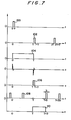
- An antenna selection signal generator 70 which actuates a switch circuit so that when the high-frequency pickup 34 detects deflection of the output of the main antenna 40, the output level of which is predicted to dip the output level after lapse of the predetermined time, is changed over to the sub antenna 42, in which no dipping in output is occurring, will now be explained with reference to Figs.-6 and 7.
- the output of the high-frequency pickup 34 is input to a level comparator 72.
- the comparator 72 outputs a mono pulse 100 and after a pulse counter 74 is reset by the pulse 100, a pulse 102 is generated every time the counter 74 counts the pulses generated by a vehicle speed pulse generator 76 up to the number of pulses which corresponds to the period T.
- a bistable multi vibrator 78 generates a signal 104 from the pulse 100, which is an ON signal, and the pulse 102, which is an OFF signal.
- a monostable multi vibrator 82 which is driven by a negative voltage produces a signal 106 which causes a pulse to be generated once the period T has elapsed.
- the signal 106 resets a pulse counter 84 which generates a pulse every time it counts up to the number of pulses which corresponds to the period D.
- signals 108 and 106 produced by the pulse counter 84 become an OFF signal and ON signal, respectively, with respect to a bistable multi vibrator 86, which produces an signal 110 serving an ON signal for a period T to T + D.
- a switch circuit 88 changes the main antenna 40 over to the sub antenna 42 for a period T to T + D in accordance with the signal 110 produced by the antenna selecting signal generator 70, and after this period has elapsed, changes the sub antenna 42 to the main antenna 40.
- the output 112 of the main antenna 40 or the sub antenna 42 is transmitted to the radio receiver.
- the output of a switch 90 which produces an output when a transmission is set in the parking range or the reverse range is divided into two.
- One is connected to the antenna selecting signal generator 70 and an AND gate 92, and the other is connected to an inverter 94.
- the output of the inverter 94 and the output of a level discriminator 96 which outputs a signal when the output of an intermediate frequency amplifier of the receiver is below a predetermined value are connected to an AND gate 98.
- Each output side of the two AND gates 92, 98 is connected to the switch circuit 88 through an OR circuit 120.
- any degeneration of the S/N ratio is prevented by the operation described in the first embodiment during travel of a vehicle.
- the degeneration of the S/N ratio is also prevented at the time of parking and reversing by having the receiving operation taken over by the antenna which is enjoying the superior receiving quality of the two antennas 40, 42 at the relevant time by automatic change-over.
- the antenna system according to the present invention enables the antenna having superior quality to be selected constantly, thereby exhibiting stable receiving sensitivity even in areas where broadcast waves are producing stationary waves due to reflection from buildings or the like.
Landscapes
- Engineering & Computer Science (AREA)
- Remote Sensing (AREA)
- Computer Networks & Wireless Communication (AREA)
- Signal Processing (AREA)
- Details Of Aerials (AREA)
- Radio Transmission System (AREA)
- Variable-Direction Aerials And Aerial Arrays (AREA)
- Support Of Aerials (AREA)
Priority Applications (1)
| Application Number | Priority Date | Filing Date | Title |
|---|---|---|---|
| AT86300548T ATE74478T1 (de) | 1985-02-01 | 1986-01-28 | Kraftfahrzeugantennenanlage. |
Applications Claiming Priority (2)
| Application Number | Priority Date | Filing Date | Title |
|---|---|---|---|
| JP18867/85 | 1985-02-01 | ||
| JP60018867A JPS61177801A (ja) | 1985-02-01 | 1985-02-01 | 自動車用アンテナ装置 |
Publications (3)
| Publication Number | Publication Date |
|---|---|
| EP0190862A2 true EP0190862A2 (de) | 1986-08-13 |
| EP0190862A3 EP0190862A3 (en) | 1988-05-25 |
| EP0190862B1 EP0190862B1 (de) | 1992-04-01 |
Family
ID=11983487
Family Applications (1)
| Application Number | Title | Priority Date | Filing Date |
|---|---|---|---|
| EP86300548A Expired - Lifetime EP0190862B1 (de) | 1985-02-01 | 1986-01-28 | Kraftfahrzeugantennenanlage |
Country Status (7)
| Country | Link |
|---|---|
| US (1) | US4742567A (de) |
| EP (1) | EP0190862B1 (de) |
| JP (1) | JPS61177801A (de) |
| AT (1) | ATE74478T1 (de) |
| CA (1) | CA1249053A (de) |
| DE (1) | DE3684623D1 (de) |
| DK (1) | DK48786A (de) |
Cited By (2)
| Publication number | Priority date | Publication date | Assignee | Title |
|---|---|---|---|---|
| US4882589A (en) * | 1986-12-29 | 1989-11-21 | Hughes Aircraft Company | Coherent switching system for a multiple beam antenna |
| AU639927B2 (en) * | 1989-05-18 | 1993-08-12 | Nec Corporation | Diversity receiving apparatus |
Families Citing this family (17)
| Publication number | Priority date | Publication date | Assignee | Title |
|---|---|---|---|---|
| US5056153A (en) * | 1987-07-29 | 1991-10-08 | Mazda Motor Corporation | Mobile electric accessory apparatus |
| US5203024A (en) * | 1990-04-27 | 1993-04-13 | Nippon Telegraph & Telephone Corp. | Antenna selection diversity reception system |
| US5481571A (en) * | 1993-11-12 | 1996-01-02 | Pacific Communication Sciences, Inc. | Method and apparatus for switching between radio frequency circuits |
| US5603107A (en) * | 1995-06-09 | 1997-02-11 | Ford Motor Company | Switching system for diversity antenna FM receiver |
| US5842118A (en) * | 1996-12-18 | 1998-11-24 | Micron Communications, Inc. | Communication system including diversity antenna queuing |
| US6289209B1 (en) | 1996-12-18 | 2001-09-11 | Micron Technology, Inc. | Wireless communication system, radio frequency communications system, wireless communications method, radio frequency communications method |
| EP1182800B1 (de) * | 2000-08-24 | 2009-04-15 | Continental Automotive GmbH | Empfangssystem mit Antennendiversität |
| USD587691S1 (en) | 2004-03-29 | 2009-03-03 | Impinj, Inc. | Radio frequency identification tag antenna assembly |
| US7528728B2 (en) * | 2004-03-29 | 2009-05-05 | Impinj Inc. | Circuits for RFID tags with multiple non-independently driven RF ports |
| US7667589B2 (en) * | 2004-03-29 | 2010-02-23 | Impinj, Inc. | RFID tag uncoupling one of its antenna ports and methods |
| US7423539B2 (en) * | 2004-03-31 | 2008-09-09 | Impinj, Inc. | RFID tags combining signals received from multiple RF ports |
| US7893813B2 (en) * | 2005-07-28 | 2011-02-22 | Intermec Ip Corp. | Automatic data collection device, method and article |
| WO2007035863A2 (en) | 2005-09-21 | 2007-03-29 | Intermec Ip Corp. | Radio frequency identification tags based on coalition formation |
| US8120461B2 (en) * | 2006-04-03 | 2012-02-21 | Intermec Ip Corp. | Automatic data collection device, method and article |
| US8002173B2 (en) * | 2006-07-11 | 2011-08-23 | Intermec Ip Corp. | Automatic data collection device, method and article |
| US7579955B2 (en) | 2006-08-11 | 2009-08-25 | Intermec Ip Corp. | Device and method for selective backscattering of wireless communications signals |
| US7616120B1 (en) | 2007-02-28 | 2009-11-10 | Impinj, Inc. | Multiple RF-port modulator for RFID tag |
Family Cites Families (6)
| Publication number | Priority date | Publication date | Assignee | Title |
|---|---|---|---|---|
| CA1048121A (en) * | 1974-04-18 | 1979-02-06 | Willis T. Lawrence | Automatic vehicle monitoring system |
| US4167738A (en) * | 1977-06-27 | 1979-09-11 | Dennis Kirkendall | Antenna mounted tuning indicator |
| US4332032A (en) * | 1979-05-24 | 1982-05-25 | Lockheed Corporation | Adaptive hybrid antenna system |
| US4566133A (en) * | 1982-12-27 | 1986-01-21 | Commtech International | Switched diversity method and apparatus for FM receivers |
| US4499606A (en) * | 1982-12-27 | 1985-02-12 | Sri International | Reception enhancement in mobile FM broadcast receivers and the like |
| JPS59181732A (ja) * | 1983-03-31 | 1984-10-16 | Toshiba Corp | 携帯用無線機におけるダイバ−シチ−受信方式 |
-
1985
- 1985-02-01 JP JP60018867A patent/JPS61177801A/ja active Pending
-
1986
- 1986-01-28 AT AT86300548T patent/ATE74478T1/de active
- 1986-01-28 EP EP86300548A patent/EP0190862B1/de not_active Expired - Lifetime
- 1986-01-28 CA CA000500475A patent/CA1249053A/en not_active Expired
- 1986-01-28 DE DE8686300548T patent/DE3684623D1/de not_active Expired - Lifetime
- 1986-01-30 US US06/824,264 patent/US4742567A/en not_active Expired - Lifetime
- 1986-01-31 DK DK48786A patent/DK48786A/da unknown
Cited By (2)
| Publication number | Priority date | Publication date | Assignee | Title |
|---|---|---|---|---|
| US4882589A (en) * | 1986-12-29 | 1989-11-21 | Hughes Aircraft Company | Coherent switching system for a multiple beam antenna |
| AU639927B2 (en) * | 1989-05-18 | 1993-08-12 | Nec Corporation | Diversity receiving apparatus |
Also Published As
| Publication number | Publication date |
|---|---|
| DK48786D0 (da) | 1986-01-31 |
| DE3684623D1 (de) | 1992-05-07 |
| EP0190862A3 (en) | 1988-05-25 |
| EP0190862B1 (de) | 1992-04-01 |
| ATE74478T1 (de) | 1992-04-15 |
| US4742567A (en) | 1988-05-03 |
| JPS61177801A (ja) | 1986-08-09 |
| DK48786A (da) | 1986-08-02 |
| CA1249053A (en) | 1989-01-17 |
Similar Documents
| Publication | Publication Date | Title |
|---|---|---|
| US4742567A (en) | Automobile antenna system | |
| EP0206775B1 (de) | Fahrzeugantennensystem | |
| CA1256988A (en) | Automobile antenna | |
| EP0191233B1 (de) | Kraftfahrzeugantennensystem | |
| US4845505A (en) | Automobile antenna system for diversity reception | |
| EP0182497B1 (de) | Kraftfahrzeugantenne | |
| EP0181120B1 (de) | Fahrzeugantennensystem | |
| EP0183443B1 (de) | Kraftfahrzeugantennensystem | |
| EP0183520A1 (de) | Fahrzeugantennensystem | |
| US4821042A (en) | Vehicle antenna system | |
| EP0223398B1 (de) | Fahrzeugantennensystem | |
| EP0180462B1 (de) | Fahrzeugantennensystem | |
| JPS61136304A (ja) | 自動車用アンテナ装置 | |
| EP0209235B1 (de) | Kraftfahrzeugfernsehantennensystem | |
| JPS61120503A (ja) | 車両用アンテナ装置 | |
| JPS61128608A (ja) | 自動車用アンテナ装置 | |
| JPS61159806A (ja) | 自動車用アンテナ装置 | |
| JPS61129906A (ja) | 車両用アンテナ装置 | |
| JPS61294904A (ja) | 自動車用tvアンテナ | |
| JPS61294902A (ja) | 自動車用アンテナ装置 | |
| JPS61174802A (ja) | 自動車用アンテナ装置 | |
| JPS623503A (ja) | 自動車用tvアンテナ装置 | |
| JPS623504A (ja) | 自動車用tvアンテナ装置 | |
| JPS623507A (ja) | 自動車用アンテナ装置 | |
| JPS61140201A (ja) | 自動車用アンテナ装置 |
Legal Events
| Date | Code | Title | Description |
|---|---|---|---|
| PUAI | Public reference made under article 153(3) epc to a published international application that has entered the european phase |
Free format text: ORIGINAL CODE: 0009012 |
|
| AK | Designated contracting states |
Kind code of ref document: A2 Designated state(s): AT CH DE FR GB LI SE |
|
| PUAL | Search report despatched |
Free format text: ORIGINAL CODE: 0009013 |
|
| AK | Designated contracting states |
Kind code of ref document: A3 Designated state(s): AT CH DE FR GB LI SE |
|
| 17P | Request for examination filed |
Effective date: 19880620 |
|
| 17Q | First examination report despatched |
Effective date: 19900710 |
|
| GRAA | (expected) grant |
Free format text: ORIGINAL CODE: 0009210 |
|
| AK | Designated contracting states |
Kind code of ref document: B1 Designated state(s): AT CH DE FR GB LI SE |
|
| REF | Corresponds to: |
Ref document number: 74478 Country of ref document: AT Date of ref document: 19920415 Kind code of ref document: T |
|
| ET | Fr: translation filed | ||
| REF | Corresponds to: |
Ref document number: 3684623 Country of ref document: DE Date of ref document: 19920507 |
|
| PLBE | No opposition filed within time limit |
Free format text: ORIGINAL CODE: 0009261 |
|
| STAA | Information on the status of an ep patent application or granted ep patent |
Free format text: STATUS: NO OPPOSITION FILED WITHIN TIME LIMIT |
|
| 26N | No opposition filed | ||
| EAL | Se: european patent in force in sweden |
Ref document number: 86300548.4 |
|
| PGFP | Annual fee paid to national office [announced via postgrant information from national office to epo] |
Ref country code: SE Payment date: 19990107 Year of fee payment: 14 |
|
| PGFP | Annual fee paid to national office [announced via postgrant information from national office to epo] |
Ref country code: FR Payment date: 19990111 Year of fee payment: 14 |
|
| PGFP | Annual fee paid to national office [announced via postgrant information from national office to epo] |
Ref country code: AT Payment date: 19990113 Year of fee payment: 14 |
|
| PGFP | Annual fee paid to national office [announced via postgrant information from national office to epo] |
Ref country code: GB Payment date: 19990128 Year of fee payment: 14 |
|
| PGFP | Annual fee paid to national office [announced via postgrant information from national office to epo] |
Ref country code: DE Payment date: 19990205 Year of fee payment: 14 |
|
| PGFP | Annual fee paid to national office [announced via postgrant information from national office to epo] |
Ref country code: CH Payment date: 19990210 Year of fee payment: 14 |
|
| PG25 | Lapsed in a contracting state [announced via postgrant information from national office to epo] |
Ref country code: GB Free format text: LAPSE BECAUSE OF NON-PAYMENT OF DUE FEES Effective date: 20000128 Ref country code: AT Free format text: LAPSE BECAUSE OF NON-PAYMENT OF DUE FEES Effective date: 20000128 |
|
| PG25 | Lapsed in a contracting state [announced via postgrant information from national office to epo] |
Ref country code: SE Free format text: LAPSE BECAUSE OF NON-PAYMENT OF DUE FEES Effective date: 20000129 |
|
| PG25 | Lapsed in a contracting state [announced via postgrant information from national office to epo] |
Ref country code: LI Free format text: LAPSE BECAUSE OF NON-PAYMENT OF DUE FEES Effective date: 20000131 Ref country code: CH Free format text: LAPSE BECAUSE OF NON-PAYMENT OF DUE FEES Effective date: 20000131 |
|
| EUG | Se: european patent has lapsed |
Ref document number: 86300548.4 |
|
| REG | Reference to a national code |
Ref country code: CH Ref legal event code: PL |
|
| GBPC | Gb: european patent ceased through non-payment of renewal fee |
Effective date: 20000128 |
|
| PG25 | Lapsed in a contracting state [announced via postgrant information from national office to epo] |
Ref country code: FR Free format text: LAPSE BECAUSE OF NON-PAYMENT OF DUE FEES Effective date: 20000929 |
|
| PG25 | Lapsed in a contracting state [announced via postgrant information from national office to epo] |
Ref country code: DE Free format text: LAPSE BECAUSE OF NON-PAYMENT OF DUE FEES Effective date: 20001101 |
|
| REG | Reference to a national code |
Ref country code: FR Ref legal event code: ST |