EP0190664A1 - Redundante Steuerschaltrug - Google Patents
Redundante Steuerschaltrug Download PDFInfo
- Publication number
- EP0190664A1 EP0190664A1 EP86101195A EP86101195A EP0190664A1 EP 0190664 A1 EP0190664 A1 EP 0190664A1 EP 86101195 A EP86101195 A EP 86101195A EP 86101195 A EP86101195 A EP 86101195A EP 0190664 A1 EP0190664 A1 EP 0190664A1
- Authority
- EP
- European Patent Office
- Prior art keywords
- analog output
- controller
- operatively connected
- signal
- controllers
- Prior art date
- Legal status (The legal status is an assumption and is not a legal conclusion. Google has not performed a legal analysis and makes no representation as to the accuracy of the status listed.)
- Granted
Links
Images

Classifications
-
- G—PHYSICS
- G05—CONTROLLING; REGULATING
- G05B—CONTROL OR REGULATING SYSTEMS IN GENERAL; FUNCTIONAL ELEMENTS OF SUCH SYSTEMS; MONITORING OR TESTING ARRANGEMENTS FOR SUCH SYSTEMS OR ELEMENTS
- G05B9/00—Safety arrangements
- G05B9/02—Safety arrangements electric
- G05B9/03—Safety arrangements electric with multiple-channel loop, i.e. redundant control systems
Definitions
- the present invention generally relates to an electrical network in which analog signals are used to actuate a device such as a switch, pump or valve; and more particularly, to such an analog network used in activating such devices in a pressurized light water nuclear power system.
- An object of the present invention is to provide multiple control paths for an actuator of a device, such as a valve.
- Another object of the present invention is to provide a current path through redundant analog output circuits in an analog output network, so that each analog output circuit can detect that one of the analog output circuits is in an on-line mode, to provide an alternate current path for actuation of the actuator, so that the actuator can be activated even if the current path through a back-up analog output circuit is defective or unavailable, to provide a feedback signal in each of the analog output circuits so that analog output circuits which are in a back-up mode do not generate an output signal as long as an output signal is being generated by an on-line analog output circuit, to provide a controller for each of the analog output circuits, each controller generating a demand signal for the corresponding analog output circuit and receiving a feedback signal from the corresponding analog output circuit, so that the controller for the on-line analog output circuit can detect a failure thereof via the feedback signal, provide a controller selector in the analog output network which receives a control signal and pulses from the controller of the on-line analog output circuit and generates an enable signal for the on-line analog
- a further object of the present invention is to provide an analog output network which includes a con- trailer selector divided into mirror image portions, each portion of the controller selector corresponding to a controller in the network, the portions of the controller selector being interconnected but capable of operating independently.
- the invention in its broad form comprises an analog output network for controlling an electrical actuator in dependence upon an input signal received from a sensor, comprising control means, operatively connepted to the sensor, for providing control signals in dependence upon the input signal; analog output circuits, each of said analog output circuits comprising actuation means operatively connected to said control means for generating an analog output signal in dependence upon one of the control signals characterized by internal loop means operatively connected to said actuation means for outputting the analog output signal and providing a current path; and loop sensing means operatively connected to said internal loop means, said actuation means and said control means, for generating a feedback signal in dependence upon electrical current flow in the current path provided by said internal loop means, and external loop means operatively connected to said analog output circuits and the actuator, for providing alternate current paths, the current path provided by said internal loop means in each of said analog output circuits being connected in parallel with one of the alternate current paths.
- a preferred embodiment described herein provides an analog output network for controlling an actuator in dependence upon an input signal received by first and second controllers from a sensor.
- the controllers are connected to a controller selector for indicating which of the controllers is in an on-line mode and which of the controllers is in a back-up mode.
- Each of the controllers is also connected to a corresponding analog output circuit which includes actuation means for generating an actuation signal, output terminals, a diode connected to one of the output terminals, and a resistor connected to the diode and the other of the output terminals.
- the analog output network further includes a first diode string connected to the actuator and the first output terminal of the first analog output circuit and includes a second diode string connected to the first diode string, the second analog output circuit and the actuator.
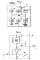
- FIG. 1 An example of such an analog output network is illustrated in Fig. 1.
- Sensors 12, 14 and 16 are located at various points in the nuclear power system.
- Sensor 14 is an example of a shared sensor which provides input signals to both controller 18 and controller 20.
- Sensors 12 and 16 are examples of redundant sensors both of which sense the same condition, e.g., temperature at a location in the nuclear power system, and each of which provide input signals to one of the controllers 18 or 20.
- an analog output network according to the present invention may derive its input signals from shared sensors only, redundant sensors only, or a combination, such as that illustrated in Fig. 1.
- the controllers 18 and 20 generate demand signals indicating an amount of activation of a device 21 such as a valve.
- the controller block diagram in Fig. 2 is an example of the construction of controllers 18 and 20, however, any process controller which provides the signals described below can be used.
- the controller illustrated in Fig. 2 utilizes a microprocessor 22, such as iSBC-286/10 manufactured by Intel Corporation connected to a memory 24, such as iSBC-556 manufactured by Intel.
- the controller 18 also includes a digital input/output interface 26, such as iSBC-556 manufactured by Intel; a digital/analog converter 28, such as MP8316-V manufactured by Burr-Brown Research Corporation; and analog/digital converters 30 and 32, such as ISV-88/40 manufactured by Intel.
- the components of the controller 18 are connected via a bus 34, e.g. the multibus used with the above components.
- the controllers 18 and 20 are connected to a controller selector 36 containing solid state components.
- the controller selector 36 may be a single "keep alive" circuit, such as the circuit illustrated in Fig. 3, if the controller 18 is preselected as a primary controller which is normally in the on-line mode and controller 20 is preselected as a secondary controller which is normally in the back-up mode.
- the keep alive circuit typically includes a monostable circuit 41, such as MC1555 manufactured by Motorola, connected to receive pulses P from the digital input/output interface 26 in the primary controller 18. So long as the pulses P are received with the proper timing, e.g.
- a high signal e.g., 5 volts
- a control signal C is also output from the digital input/output interface 26 in the primary controller 18. The control signal C is received at the output of the monostable circuit 41 so that absence of either the control signal C or the output of the monostable circuit 41 causes the voltage at node @ to drop to a low voltage, e.g., zero volts.
- Inverters 42 have commonly connected gates so that either can fail and the other will still invert the output at node A , whereby when the primary controller 18 is in an on-line mode, an enable signal E A , having a "low true" value, is output by the controller selector 36 to, the analog output circuit 38 corresponding to the primary controller 18.
- An inverter 43 inverts the enable signal E A to be output as the enable signal E B .
- a switch 44 is connected between node @ and ground to force the selection of the back-up controller 20 as the on-line controller.
- controller selector 36 must receive pulse and control signals from both controllers 18 and 20 and supply an operating status signal to each controller 18 or 20 indicating the status of the other controller 20 or 18.
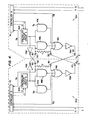
- a controller selector is illustrated in Fig. 4 which supplies such signals.
- the circuit illustrated in Fig. 4 includes cross-coupled selector circuits 36A and 36B.
- the selector circuits 36A and 36B comprise controller status circuits 46A and 46B for each of the controllers 18 and 20, respectively.
- the controller status circuits 46A and 46B perform the same function as the monostable circuit 41 in the circuit illustrated in Fig. 3.
- the outputs from the keep alive circuits 46A and 46B are supplied to AND gates 47A, 48A, 47B and 48B.
- the AND gates 47A and 47B receive select signals S A and S B , respectively, for example signals generated by normally closed switches.
- the outputs from the controller status circuits 46A and 46B are also supplied to inverters 49A and 49B which supply an operation status signal 0A or O B to the other controller 20 or 18 and to the AND gates 48B and 48A, respectively, via cable connectors 50.
- the AND gates 47A and 47B indicate that the corresponding controller 18 or 20 is to be selected when a corresponding switch is depressed if the corresponding controller 18 or 20 is operating normally, as indicated by the corresponding controller status circuit 46A or 46B.
- the AND gates 48A and 48B switch control from an on-line controller, e.g. controller 18, to a back-up controller, e.g.
- controller 20 when the controller status circuit, e.g., 46A, corresponding to the on-line controller 18 indicates that the controller 18 is no longer operating normally and the controller status circuit, e.g., 46B, corresponding to the back-up controller 20, indicates that the back-up controller 20 is alive.
- the controller status circuit e.g., 46A
- the controller status circuit e.g., 46B
- OR gates 51A and 51B so that either of the above conditions can result in a change in enable status.
- the output of the OR gates 51A and 51B pass through inverters 52A and 52B prior to being output'as the "low true" enable signals.
- the enable signals are also fed back to the opposite OR gate 51B or 51A and to the controller 20 or 18 corresponding thereto.
- the OR gates 51A and 51B and inverters 52A and 52B form a latch circuit which latches an existing pair of signals enabling only one of the two analog output circuits 38 and 40 until there is a change in status caused by depressing one of the switches 44 or 45, a change in status indicated by one of the controller status circuits 46A or 46B, or a circuit failure.
- the cable connectors 50 indicate the separation of the controller selector 36, illustrated in Fig. 4, into two portions 36A and 36B, each of which is capable of generating an enable signal without inputs from the other portion, and again providing redundant signal generation and signal paths.
- the analog output circuits 38 and 40 are modified versions of the circuits disclosed in the U.S. patent application by Sutherland and Kenny, entitled “Low Power Dissipation Analog Current Loop Output Circuit", having applicants' Docket No. 52,204 and the same assignee as the present application.
- the analog output circuits 38 and 40 each include a pulse width modulator 53 connected to a corresponding controller 18 or 20 and to the controller selector 36. Also included are a transformer 54 connected to the pulse width modulator 53, a rectifier-filter 55 connected to the transformer 54, and a diode 56 connected across the outputs of the rectifier-filter 55.
- a resistor 58 is connected to one of the outputs of the rectifier-filter 55 and to the diode 56.
- An electrically isolated amplifier 60 such as an opto- isolated differential amplifier, is connected to the resistor 58 to sense the voltage drop across the resistor 58.
- the amplifier 60 generates a feedback signal which is supplied to the pulse width modulator 53 and to the corresponding controller 18 or 20.
- the outputs of the rectifier-filter 55 are connected to output terminals 61 and 62 of the analog output circuit 38 or 40 via the resistor 58 and a surge withstand circuit 63.
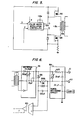
- the pulse width modulator 53 preferably includes a solid state pulse-modulation controller 64 such as illustrated in Fig. 5.
- the pulse width modulation controller 64 is preferably in the form of an integrated circuit such as the regulating pulse modulator identified as LM3524 and manufactured by National Semiconductor Corporation, or an equivalent integrated circuit.
- the pulse width modulation controller 64 receives a demand signal from the corresponding controller 18 or 20 and a feedback signal from the amplifier 60.
- the modulation controller 64 outputs a pulse train and an inverted pulse train with a duty cycle which increases when the feedback signal is lower than the demand signal.
- the pulse trains control power transistors 66 and 68 which permit current to flow through the transformer 54.
- the rectifier-filter 55 and surge withstand circuit 63 are conventional circuits, examples of which are illustrated in Fig. 6.
- the feedback signal generated by the amplifier 60 indicates the voltage drop across the resistor 58.
- the feedback signal is also supplied to the corresponding controller 18 or 20.
- the corresponding controller 18 or 20 ceases to output the pulses and drops the output of the control signal to a "low" value, e.g., zero volts.
- controller 18 Assuming that controller 18 is "on-line", the cessation of the pulse train or a low control signal from controller 18 will cause the controller selector 36 to disable the pulse width modulator 53 in the analog output circuit 38 and enable the pulse width modulator 53 in the analog output circuit 40 while simultaneously indicating the change in status to controller 20.
- the output terminals 61 and 62 of the analog output circuits 38 and 40 are connected to diode strings 70 and 72 and to the actuator 74.
- the actuator 74 may be an electro-pneumatic positioner or transducer, such as those commonly used in control systems of a nuclear power system to control the operation of the device 21 which may be a pump or valve, etc.
- Such actuators typically operate with a current of 4-20 milliamperes or 10-50 milliamperes.
- the maximum current through the resistor 58 will be 20 or 50 milliamperes, depending on the type of actuator 74 to which the analog output network is connected.
- the diode string 72 is illustrated as including a zener diode 78 and a high-power, reverse-bias diode 80, such as a Tranzorb diode manufactured by General Semiconductor Industries, Inc.
- the zener diode 78 is preferably a low-voltage zener diode with a breakdown voltage of 3-5 volts.
- An alternative diode string is the diode string 70 illustrated as a series of Tranzorb diodes which have a total forward-bias voltage drop equivalent to that of the zener-Tranzorb combination of diode string 72. While both types of diode strings are illustrated in Fig. 1, an actual analog output network would likely use the same type for both diode strings 70 and 72.
- the diode strings 70 and 72 are included to provide an alternate current path for actuation of the actuator 74.
- one of the controllers 18 or 20 is in an on-line mode and thus generates a higher voltage demand signal than the controller 20 or 18 which is in a back-up mode.
- the analog output circuit 38 or 40 corresponding to the on-line controller 18 or 20, generates an output signal which is desired to pass through the actuator 74 and through the resistor 58 and diode 56 of the back-up analog output circuit 40 or 38.
- the voltage drop across each of the diode strings 70 and 72 must be higher than the voltage drop across the resistor 58 and diode 56 caused by the maximum expected current, e.g., 20 milliamperes or 50 milliamperes.
- the amplifier 60 in the back-up analog output circuit 40 or 38 will sense a voltage drop across the resistor 58 which is higher than the demand generated by the back-up controller 20 or 18, and thus will prevent the pulse width modulator 53 in the back-up analog output circuit 40 or 38 from generating an actuation signal, even if the enable signal does not have a-"high" or "disable” value. Therefore, it would be possible to practice the present invention with a modulation controller which does not have an enable/disable pin; however, the number of communication paths provided by the above embodiment would be reduced.
- the above-described analog output network provides multiple communication paths between the redundant portions of the network.
- the analog output circuits 38 and 40 provide an alternate communication path.
- the on-line analog output circuit 38 or 40 fails to supply the actuator 74 with an actuation signal, the voltage drop across resistor 58 in the back-up analog output circuit 40 or 38 will drop to zero causing the feedback signal output by the amplifier 60 to drop below the demand signal with the result that the pulse width modulator 50 in the back-up analog output circuit 40 or 38 will turn on and generate an actuation signal. In other words, an actuation signal will be generated by the back-up analog output circuit 40 or 38 to substitute for the actuation signal from the failed analog output circuit 38 or 40.
- the diode string 72 or 70 will provide an alternate current path for current to flow through the actuator 74 and return to the on-line analog output circuit 38 or 40.
- This feature also permits one of the analog output circuits 38 or 40 and the corresponding surge withstand circuit 63 to be removed for maintenance while the remaining analog output circuit 40 or 38 can be used for control of the actuator 74.
Landscapes
- Physics & Mathematics (AREA)
- General Physics & Mathematics (AREA)
- Engineering & Computer Science (AREA)
- Automation & Control Theory (AREA)
- Safety Devices In Control Systems (AREA)
- Feedback Control In General (AREA)
- Small-Scale Networks (AREA)
Applications Claiming Priority (2)
| Application Number | Priority Date | Filing Date | Title |
|---|---|---|---|
| US06/699,367 US4652417A (en) | 1985-02-07 | 1985-02-07 | Fault-tolerant analog output network |
| US699367 | 1985-02-07 |
Publications (2)
| Publication Number | Publication Date |
|---|---|
| EP0190664A1 true EP0190664A1 (de) | 1986-08-13 |
| EP0190664B1 EP0190664B1 (de) | 1991-06-05 |
Family
ID=24809003
Family Applications (1)
| Application Number | Title | Priority Date | Filing Date |
|---|---|---|---|
| EP86101195A Expired - Lifetime EP0190664B1 (de) | 1985-02-07 | 1986-01-30 | Redundante Steuerschaltrug |
Country Status (4)
| Country | Link |
|---|---|
| US (1) | US4652417A (de) |
| EP (1) | EP0190664B1 (de) |
| JP (1) | JPH0797281B2 (de) |
| ES (1) | ES8707807A1 (de) |
Cited By (10)
| Publication number | Priority date | Publication date | Assignee | Title |
|---|---|---|---|---|
| GB2200225A (en) * | 1987-01-24 | 1988-07-27 | Lucas Ind Plc | Computer control of an apparatus, |
| EP0329774A4 (en) * | 1987-08-31 | 1991-09-04 | Triplex | Fault-tolerant output circuits |
| US5293485A (en) * | 1988-09-13 | 1994-03-08 | Kabushiki Kaisha Toshiba | Display control apparatus for converting color/monochromatic CRT gradation into flat panel display gradation |
| US5475402A (en) * | 1992-06-04 | 1995-12-12 | Kabushiki Kaisha Toshiba | Display control apparatus and method |
| GB2295032A (en) * | 1994-11-14 | 1996-05-15 | Ibm | Fault tolerant cooling in a data storage system |
| US5629715A (en) * | 1989-09-29 | 1997-05-13 | Kabushiki Kaisha Toshiba | Display control system |
| CN106357133A (zh) * | 2016-10-17 | 2017-01-25 | 株洲四方电气有限公司 | 一种用于大功率整流器的双通道热备用控制装置 |
| EP4177680A1 (de) * | 2021-11-03 | 2023-05-10 | Hamilton Sundstrand Corporation | Redundanter fehlerschutz für ein steuerungssystem mit nur zwei steuergeräten |
| EP4195436A1 (de) * | 2021-12-07 | 2023-06-14 | Hamilton Sundstrand Corporation | Festkörperleistungsregler |
| WO2025237515A1 (en) | 2024-05-15 | 2025-11-20 | Framatome Gmbh | Safety control system and method for operating the same |
Families Citing this family (17)
| Publication number | Priority date | Publication date | Assignee | Title |
|---|---|---|---|---|
| US5146401A (en) * | 1989-09-05 | 1992-09-08 | Honeywell Inc. | Apparatus for providing a universal interface in a process control system |
| US5442544A (en) * | 1990-01-26 | 1995-08-15 | Honeywell Inc. | Single input single output rate optimal controller |
| US7182272B1 (en) * | 2001-09-28 | 2007-02-27 | Hydropoint Data Systems, Inc. | System and method for facilitating control of irrigation systems |
| CA2515775A1 (en) | 2003-02-15 | 2004-09-02 | Gulfstream Aerospace Corporation | System and method for aircraft cabin atmospheric composition control |
| DE102005001680A1 (de) * | 2005-01-13 | 2006-07-27 | Siemens Ag | Analogausgabeeinheit |
| BRPI0706613A2 (pt) * | 2006-01-17 | 2011-04-05 | Gulfstream Aerospace Corp | aparelho e método para controle de backup em um sistema de controle de vÈo distribuìdo |
| CA2637331A1 (en) * | 2006-01-17 | 2007-07-26 | Gulfstream Aerospace Corporation | System and method for an integrated backup control system |
| KR100871857B1 (ko) * | 2007-06-11 | 2008-12-03 | 성균관대학교산학협력단 | 차량 내부의 네트워크 시스템 및 그 제어방법 |
| US8805593B2 (en) * | 2009-11-18 | 2014-08-12 | Energy Control Technologies, Inc. | Fault tolerant analog outputs for turbo compressors |
| US8760103B2 (en) | 2011-09-30 | 2014-06-24 | Honeywell International Inc. | Actuator power control circuit having fail-safe bypass switching |
| US9981529B2 (en) | 2011-10-21 | 2018-05-29 | Honeywell International Inc. | Actuator having a test mode |
| US8749182B2 (en) | 2011-11-08 | 2014-06-10 | Honeywell International Inc. | Actuator having an adjustable auxiliary output |
| US8922140B2 (en) | 2011-11-09 | 2014-12-30 | Honeywell International Inc. | Dual potentiometer address and direction selection for an actuator |
| US8588983B2 (en) | 2011-11-09 | 2013-11-19 | Honeywell International Inc. | Actuator with diagnostics |
| US9041319B2 (en) | 2011-11-09 | 2015-05-26 | Honeywell International Inc. | Actuator having an address selector |
| US10113762B2 (en) | 2011-11-09 | 2018-10-30 | Honeywell International Inc. | Actuator having an adjustable running time |
| US9106171B2 (en) | 2013-05-17 | 2015-08-11 | Honeywell International Inc. | Power supply compensation for an actuator |
Citations (2)
| Publication number | Priority date | Publication date | Assignee | Title |
|---|---|---|---|---|
| US3732501A (en) * | 1971-09-27 | 1973-05-08 | United Aircraft Corp | Redundant operational amplifier circuit for servo control systems |
| DE3021879A1 (de) * | 1980-06-11 | 1982-02-25 | Dornier System Gmbh, 7990 Friedrichshafen | Verfahren zur zuverlaessigen ansteuerung und ausfallerkennung fuer analog und digital angesteuerte antriebe |
Family Cites Families (12)
| Publication number | Priority date | Publication date | Assignee | Title |
|---|---|---|---|---|
| JPS5466092U (de) * | 1977-10-19 | 1979-05-10 | ||
| FR2413709A1 (fr) * | 1978-01-03 | 1979-07-27 | Thomson Csf | Dispositif de regulation d'une tension continue necessitant un isolement entre les circuits de regulation et d'utilisation et alimentation comportant un tel dispositif |
| DE3031360A1 (de) * | 1980-08-20 | 1982-04-08 | Robert Bosch Gmbh, 7000 Stuttgart | Einrichtung zum erzeugen von steuersignalen mit einer haupt- und einer hilfssteuereinheit |
| US4370805A (en) * | 1980-10-20 | 1983-02-01 | Plastronics Interconnections, Inc. | Circuit package handling apparatus |
| US4427620A (en) * | 1981-02-04 | 1984-01-24 | Westinghouse Electric Corp. | Nuclear reactor power supply |
| JPS5884302A (ja) * | 1981-11-16 | 1983-05-20 | Yokogawa Hokushin Electric Corp | プロセス制御装置 |
| JPS5890201A (ja) * | 1981-11-24 | 1983-05-28 | Hitachi Ltd | 三重系プロセス入出力装置 |
| JPS58115502A (ja) * | 1981-12-29 | 1983-07-09 | Mitsubishi Electric Corp | 燃料電池の温度調整装置 |
| JPS58168102A (ja) * | 1982-03-29 | 1983-10-04 | Yokogawa Hokushin Electric Corp | プロセス制御装置 |
| JPS58182701A (ja) * | 1982-04-19 | 1983-10-25 | Yokogawa Hokushin Electric Corp | プロセス制御装置 |
| US4584165A (en) * | 1983-02-09 | 1986-04-22 | General Electric Company | Redundant reactivity control system |
| JPS59163603A (ja) * | 1983-03-09 | 1984-09-14 | Fuji Electric Co Ltd | 二重化制御システム |
-
1985
- 1985-02-07 US US06/699,367 patent/US4652417A/en not_active Expired - Lifetime
-
1986
- 1986-01-30 EP EP86101195A patent/EP0190664B1/de not_active Expired - Lifetime
- 1986-02-06 ES ES551715A patent/ES8707807A1/es not_active Expired
- 1986-02-07 JP JP61024249A patent/JPH0797281B2/ja not_active Expired - Fee Related
Patent Citations (2)
| Publication number | Priority date | Publication date | Assignee | Title |
|---|---|---|---|---|
| US3732501A (en) * | 1971-09-27 | 1973-05-08 | United Aircraft Corp | Redundant operational amplifier circuit for servo control systems |
| DE3021879A1 (de) * | 1980-06-11 | 1982-02-25 | Dornier System Gmbh, 7990 Friedrichshafen | Verfahren zur zuverlaessigen ansteuerung und ausfallerkennung fuer analog und digital angesteuerte antriebe |
Cited By (11)
| Publication number | Priority date | Publication date | Assignee | Title |
|---|---|---|---|---|
| GB2200225A (en) * | 1987-01-24 | 1988-07-27 | Lucas Ind Plc | Computer control of an apparatus, |
| EP0329774A4 (en) * | 1987-08-31 | 1991-09-04 | Triplex | Fault-tolerant output circuits |
| US5293485A (en) * | 1988-09-13 | 1994-03-08 | Kabushiki Kaisha Toshiba | Display control apparatus for converting color/monochromatic CRT gradation into flat panel display gradation |
| US5629715A (en) * | 1989-09-29 | 1997-05-13 | Kabushiki Kaisha Toshiba | Display control system |
| US5475402A (en) * | 1992-06-04 | 1995-12-12 | Kabushiki Kaisha Toshiba | Display control apparatus and method |
| GB2295032A (en) * | 1994-11-14 | 1996-05-15 | Ibm | Fault tolerant cooling in a data storage system |
| CN106357133A (zh) * | 2016-10-17 | 2017-01-25 | 株洲四方电气有限公司 | 一种用于大功率整流器的双通道热备用控制装置 |
| EP4177680A1 (de) * | 2021-11-03 | 2023-05-10 | Hamilton Sundstrand Corporation | Redundanter fehlerschutz für ein steuerungssystem mit nur zwei steuergeräten |
| EP4195436A1 (de) * | 2021-12-07 | 2023-06-14 | Hamilton Sundstrand Corporation | Festkörperleistungsregler |
| US12271172B2 (en) | 2021-12-07 | 2025-04-08 | Hamilton Sundstrand Corporation | Solid state power controllers |
| WO2025237515A1 (en) | 2024-05-15 | 2025-11-20 | Framatome Gmbh | Safety control system and method for operating the same |
Also Published As
| Publication number | Publication date |
|---|---|
| ES551715A0 (es) | 1987-08-16 |
| US4652417A (en) | 1987-03-24 |
| ES8707807A1 (es) | 1987-08-16 |
| JPS61187001A (ja) | 1986-08-20 |
| JPH0797281B2 (ja) | 1995-10-18 |
| EP0190664B1 (de) | 1991-06-05 |
Similar Documents
| Publication | Publication Date | Title |
|---|---|---|
| US4652417A (en) | Fault-tolerant analog output network | |
| US4409635A (en) | Electrical power system with fault tolerant control unit | |
| US4667284A (en) | Multiplexing control unit | |
| US3888772A (en) | Communication between redundant protection and safeguards logic systems within nuclear reactor power plants by means of light | |
| EP0241270B1 (de) | Sich selbst prüfende Überwachungsschaltung | |
| US7149925B2 (en) | Peripheral component with high error protection for stored programmable controls | |
| US4697093A (en) | Testable, fault-tolerant power interface circuit for controlling plant process equipment | |
| WO1990010332A1 (en) | Fail-safe and fault-tolerant alternating current output circuit | |
| JP2013529832A (ja) | 設備のフェールセーフな接続または接続解除のための安全回路 | |
| US4910659A (en) | Input and output peripheral controller cards for use in a programmable logic controller system | |
| US4215340A (en) | Process for the automatic signalling of faults of a static automatic module and a module for realizing the process | |
| US5613064A (en) | Output network for a fault tolerant control system | |
| GB1565307A (en) | Fail-safe outpot unit for a data processing installation | |
| US4075502A (en) | Monitoring device | |
| EP1078304B1 (de) | Selbstüberprüfendes ausgangsmodul | |
| US4009420A (en) | Solid state power controller | |
| US3965432A (en) | High reliability pulse source | |
| GB1569049A (en) | Direct current supply voltage monitoring apparatus | |
| RU2680088C1 (ru) | Релейный коммутатор | |
| SU1379829A1 (ru) | Устройство дл контрол исправности релейной защиты | |
| SU1169079A1 (ru) | Переключатель напряжения | |
| SU687441A1 (ru) | Устройство дл контрол и сигнализации о неисправност х по меньшей мере двух вторичных источников питани | |
| EA051041B1 (ru) | Усовершенствованное устройство мониторинга состояния для мониторинга состояния исполнительного механизма | |
| SU1624543A1 (ru) | Устройство дл управлени индуктивной нагрузкой со встроенным контролем | |
| SU1273886A1 (ru) | Устройство дл контрол системы управлени электроприводом |
Legal Events
| Date | Code | Title | Description |
|---|---|---|---|
| PUAI | Public reference made under article 153(3) epc to a published international application that has entered the european phase |
Free format text: ORIGINAL CODE: 0009012 |
|
| AK | Designated contracting states |
Kind code of ref document: A1 Designated state(s): BE FR GB IT SE |
|
| 17P | Request for examination filed |
Effective date: 19870210 |
|
| 17Q | First examination report despatched |
Effective date: 19881213 |
|
| GRAA | (expected) grant |
Free format text: ORIGINAL CODE: 0009210 |
|
| AK | Designated contracting states |
Kind code of ref document: B1 Designated state(s): BE FR GB IT SE |
|
| ET | Fr: translation filed | ||
| ITF | It: translation for a ep patent filed | ||
| PLBE | No opposition filed within time limit |
Free format text: ORIGINAL CODE: 0009261 |
|
| STAA | Information on the status of an ep patent application or granted ep patent |
Free format text: STATUS: NO OPPOSITION FILED WITHIN TIME LIMIT |
|
| 26N | No opposition filed | ||
| PGFP | Annual fee paid to national office [announced via postgrant information from national office to epo] |
Ref country code: FR Payment date: 19931215 Year of fee payment: 9 |
|
| PGFP | Annual fee paid to national office [announced via postgrant information from national office to epo] |
Ref country code: SE Payment date: 19931220 Year of fee payment: 9 |
|
| PGFP | Annual fee paid to national office [announced via postgrant information from national office to epo] |
Ref country code: BE Payment date: 19940112 Year of fee payment: 9 |
|
| EAL | Se: european patent in force in sweden |
Ref document number: 86101195.5 |
|
| PG25 | Lapsed in a contracting state [announced via postgrant information from national office to epo] |
Ref country code: SE Effective date: 19950131 Ref country code: BE Effective date: 19950131 |
|
| BERE | Be: lapsed |
Owner name: WESTINGHOUSE ELECTRIC CORP. Effective date: 19950131 |
|
| PG25 | Lapsed in a contracting state [announced via postgrant information from national office to epo] |
Ref country code: FR Effective date: 19950929 |
|
| EUG | Se: european patent has lapsed |
Ref document number: 86101195.5 |
|
| REG | Reference to a national code |
Ref country code: FR Ref legal event code: ST |
|
| PGFP | Annual fee paid to national office [announced via postgrant information from national office to epo] |
Ref country code: GB Payment date: 19991202 Year of fee payment: 15 |
|
| PG25 | Lapsed in a contracting state [announced via postgrant information from national office to epo] |
Ref country code: GB Free format text: LAPSE BECAUSE OF NON-PAYMENT OF DUE FEES Effective date: 20010130 |
|
| GBPC | Gb: european patent ceased through non-payment of renewal fee |
Effective date: 20010130 |
|
| PG25 | Lapsed in a contracting state [announced via postgrant information from national office to epo] |
Ref country code: IT Free format text: LAPSE BECAUSE OF NON-PAYMENT OF DUE FEES;WARNING: LAPSES OF ITALIAN PATENTS WITH EFFECTIVE DATE BEFORE 2007 MAY HAVE OCCURRED AT ANY TIME BEFORE 2007. THE CORRECT EFFECTIVE DATE MAY BE DIFFERENT FROM THE ONE RECORDED. Effective date: 20050130 |