EP0190529B1 - Remotely controlled flow-responsive actuating device, in particular for actuating a stabilizer in a drill string - Google Patents
Remotely controlled flow-responsive actuating device, in particular for actuating a stabilizer in a drill string Download PDFInfo
- Publication number
- EP0190529B1 EP0190529B1 EP85402657A EP85402657A EP0190529B1 EP 0190529 B1 EP0190529 B1 EP 0190529B1 EP 85402657 A EP85402657 A EP 85402657A EP 85402657 A EP85402657 A EP 85402657A EP 0190529 B1 EP0190529 B1 EP 0190529B1
- Authority
- EP
- European Patent Office
- Prior art keywords
- piston
- profiled
- fluid
- duct
- actuation
- Prior art date
- Legal status (The legal status is an assumption and is not a legal conclusion. Google has not performed a legal analysis and makes no representation as to the accuracy of the status listed.)
- Expired
Links
- 239000003381 stabilizer Substances 0.000 title claims abstract description 22
- 239000012530 fluid Substances 0.000 claims abstract description 55
- 238000011144 upstream manufacturing Methods 0.000 claims abstract description 6
- 230000002829 reductive effect Effects 0.000 claims abstract description 5
- 238000005553 drilling Methods 0.000 claims description 65
- 238000005086 pumping Methods 0.000 claims description 19
- 230000006641 stabilisation Effects 0.000 claims description 10
- 238000011105 stabilization Methods 0.000 claims description 10
- 238000009530 blood pressure measurement Methods 0.000 claims description 4
- 230000000670 limiting effect Effects 0.000 claims description 3
- 238000006073 displacement reaction Methods 0.000 description 19
- 238000009434 installation Methods 0.000 description 13
- 239000012071 phase Substances 0.000 description 7
- 238000010586 diagram Methods 0.000 description 4
- 238000000605 extraction Methods 0.000 description 4
- 239000004459 forage Substances 0.000 description 3
- 125000006850 spacer group Chemical group 0.000 description 3
- 230000000087 stabilizing effect Effects 0.000 description 3
- XLYOFNOQVPJJNP-UHFFFAOYSA-N water Substances O XLYOFNOQVPJJNP-UHFFFAOYSA-N 0.000 description 3
- 230000003247 decreasing effect Effects 0.000 description 2
- 230000000694 effects Effects 0.000 description 2
- 238000002347 injection Methods 0.000 description 2
- 239000007924 injection Substances 0.000 description 2
- 230000003993 interaction Effects 0.000 description 2
- 238000005259 measurement Methods 0.000 description 2
- 239000012528 membrane Substances 0.000 description 2
- 230000002093 peripheral effect Effects 0.000 description 2
- 230000000750 progressive effect Effects 0.000 description 2
- 230000000295 complement effect Effects 0.000 description 1
- 229930195733 hydrocarbon Natural products 0.000 description 1
- 150000002430 hydrocarbons Chemical class 0.000 description 1
- 239000012073 inactive phase Substances 0.000 description 1
- 230000002262 irrigation Effects 0.000 description 1
- 238000003973 irrigation Methods 0.000 description 1
- 238000003754 machining Methods 0.000 description 1
- 238000012423 maintenance Methods 0.000 description 1
- 239000003208 petroleum Substances 0.000 description 1
- 230000000284 resting effect Effects 0.000 description 1
- 230000002441 reversible effect Effects 0.000 description 1
- 238000007789 sealing Methods 0.000 description 1
- 239000007787 solid Substances 0.000 description 1
- 230000008961 swelling Effects 0.000 description 1
- 238000004078 waterproofing Methods 0.000 description 1
Images


Classifications
-
- E—FIXED CONSTRUCTIONS
- E21—EARTH OR ROCK DRILLING; MINING
- E21B—EARTH OR ROCK DRILLING; OBTAINING OIL, GAS, WATER, SOLUBLE OR MELTABLE MATERIALS OR A SLURRY OF MINERALS FROM WELLS
- E21B34/00—Valve arrangements for boreholes or wells
- E21B34/06—Valve arrangements for boreholes or wells in wells
- E21B34/10—Valve arrangements for boreholes or wells in wells operated by control fluid supplied from outside the borehole
-
- E—FIXED CONSTRUCTIONS
- E21—EARTH OR ROCK DRILLING; MINING
- E21B—EARTH OR ROCK DRILLING; OBTAINING OIL, GAS, WATER, SOLUBLE OR MELTABLE MATERIALS OR A SLURRY OF MINERALS FROM WELLS
- E21B17/00—Drilling rods or pipes; Flexible drill strings; Kellies; Drill collars; Sucker rods; Cables; Casings; Tubings
- E21B17/10—Wear protectors; Centralising devices, e.g. stabilisers
- E21B17/1014—Flexible or expansible centering means, e.g. with pistons pressing against the wall of the well
-
- E—FIXED CONSTRUCTIONS
- E21—EARTH OR ROCK DRILLING; MINING
- E21B—EARTH OR ROCK DRILLING; OBTAINING OIL, GAS, WATER, SOLUBLE OR MELTABLE MATERIALS OR A SLURRY OF MINERALS FROM WELLS
- E21B21/00—Methods or apparatus for flushing boreholes, e.g. by use of exhaust air from motor
- E21B21/10—Valve arrangements in drilling-fluid circulation systems
-
- E—FIXED CONSTRUCTIONS
- E21—EARTH OR ROCK DRILLING; MINING
- E21B—EARTH OR ROCK DRILLING; OBTAINING OIL, GAS, WATER, SOLUBLE OR MELTABLE MATERIALS OR A SLURRY OF MINERALS FROM WELLS
- E21B33/00—Sealing or packing boreholes or wells
- E21B33/10—Sealing or packing boreholes or wells in the borehole
- E21B33/12—Packers; Plugs
- E21B33/127—Packers; Plugs with inflatable sleeve
-
- E—FIXED CONSTRUCTIONS
- E21—EARTH OR ROCK DRILLING; MINING
- E21B—EARTH OR ROCK DRILLING; OBTAINING OIL, GAS, WATER, SOLUBLE OR MELTABLE MATERIALS OR A SLURRY OF MINERALS FROM WELLS
- E21B43/00—Methods or apparatus for obtaining oil, gas, water, soluble or meltable materials or a slurry of minerals from wells
- E21B43/11—Perforators; Permeators
- E21B43/112—Perforators with extendable perforating members, e.g. actuated by fluid means
-
- E—FIXED CONSTRUCTIONS
- E21—EARTH OR ROCK DRILLING; MINING
- E21B—EARTH OR ROCK DRILLING; OBTAINING OIL, GAS, WATER, SOLUBLE OR MELTABLE MATERIALS OR A SLURRY OF MINERALS FROM WELLS
- E21B7/00—Special methods or apparatus for drilling
- E21B7/04—Directional drilling
- E21B7/06—Deflecting the direction of boreholes
-
- F—MECHANICAL ENGINEERING; LIGHTING; HEATING; WEAPONS; BLASTING
- F16—ENGINEERING ELEMENTS AND UNITS; GENERAL MEASURES FOR PRODUCING AND MAINTAINING EFFECTIVE FUNCTIONING OF MACHINES OR INSTALLATIONS; THERMAL INSULATION IN GENERAL
- F16K—VALVES; TAPS; COCKS; ACTUATING-FLOATS; DEVICES FOR VENTING OR AERATING
- F16K17/00—Safety valves; Equalising valves, e.g. pressure relief valves
- F16K17/20—Excess-flow valves
- F16K17/22—Excess-flow valves actuated by the difference of pressure between two places in the flow line
- F16K17/24—Excess-flow valves actuated by the difference of pressure between two places in the flow line acting directly on the cutting-off member
- F16K17/28—Excess-flow valves actuated by the difference of pressure between two places in the flow line acting directly on the cutting-off member operating in one direction only
- F16K17/30—Excess-flow valves actuated by the difference of pressure between two places in the flow line acting directly on the cutting-off member operating in one direction only spring-loaded
Definitions
- the invention relates generally to a device for the remote actuation of equipment associated with a conduit in which an incompressible fluid circulates and more particularly to a device for actuating a stabilizer of a drill string.
- tools In the field of research and exploitation of hydrocarbons, tools are used which must develop high powers to carry out operations such as drilling and which are located at the bottom of the hole at a very great distance from the place located at the surface where the means for controlling and producing the energy necessary for the implementation of the tools are arranged.
- These downhole tools are generally supplied with incompressible fluid such as a drilling mud via a very long pipe, one end of which is at the surface and the other end of which is at the bottom of the hole and allows the supply of drilling mud to the tool.
- the end of the pipe located on the surface is connected to a pumping installation which makes it possible to send drilling mud into the pipe under pressure with a certain practically constant flow during the operation of the tooling.
- Certain equipment associated with the pipe or the drill pipe and located at a very great distance from the surface must be remote-controlled, and controlled by telemetry devices. This is the case, for example, with devices allowing the orientation of the drilling tool and its trajectory control, in the case of inclined drilling.
- stabilization devices or stabilizers connected to the drill string, generally in its part adjacent to the tool.
- Such stabilizing devices comprise a body connected to the drill string and one or more blades capable of moving in the radial direction relative to the axis of the drill string.
- a control means ensures the extraction of the blades towards the outside of the stabilizer body in order to vary the support distance between the axis of the drill string and the edges of the drilled hole. Thanks to these support blades, it is possible, depending on the case (vertical drilling, inclined drilling of constant direction or change of drilling direction) to modify the radial forces exerted on the drill string and consequently on the tool in progress drilling, in the desired direction.
- control means allowing the actuation of the currently known stabilizers have a complex structure, are difficult to use and do not allow precise and perfectly controlled movements of the support blades.
- the object of the invention is to propose a device for the remote actuation of equipment associated with a conduit having a first end through which an incompressible fluid is sent by means of pumping, with a determined service flow and a second end remote from the first where the incompressible fluid is used, for example, as a working fluid, actuation device which is of a simple structure and of safe operation, which can be implemented without using a source of energy other than that supplied by the incompressible fluid and actuating elements external to the duct and the operation of which can be controlled.
- the equipment actuated by the piston being a stabilization device comprising a body connected to the drill string and at least one support blade mounted to move radially in the body
- the piston of the actuating device is mounted to move in the central bore of the body, not only in translation but also in rotation around of the axis of the drill string and it has, on its external lateral surface, longitudinal ramps, inclined in a radial direction relative to the axis of the rods, placed one after the other along the periphery of the piston and connected together to form a continuous actuation surface by complementary guide parts for the stepwise rotation of the piston and for its return to its initial position, at least one actuation finger mounted to move radially in the cooperating body with the continuous actuating surface on the one hand and the blade on the other hand for its radial extraction, during the displacement of the piston, in a first direction of displacement which is accompanied by
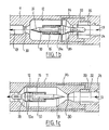
- a drilling installation which includes a drill string 1 carrying at its lower end the drilling tool 2.
- the tool 2 has been shown in the working position at the bottom of the hole 3.
- the train of hollow rods 1 constitutes a very long conduit, one end of which is connected to the tool 2 at the bottom of the hole and the other end of which which is on the surface is connected to a conduit 4 allowing the injection of drilling mud to high pressure and constant flow in the interior space of the rods 1.
- the conduit 4 is connected to a pumping installation 5 on which a measuring device 6 makes it possible to precisely determine the pumping pressure.
- the drilling mud descends in the drill string, feeds the tool 2 at the bottom of the hole and rises to the surface through the hole 3, outside the drill string 1.
- An equipment 7 for orienting the tool 2 and a telemetry assembly 8 are associated with the drill string 1, above the junction part of the tool 2 with the drill string. Pressurized drilling mud is used as the working fluid for drilling tool 2.
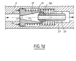
- an embodiment of an actuating device according to the invention is seen, making it possible to implement equipment such as the equipment 7 for orienting a drilling tool, at a distance, by providing it with the motive power required.
- This device is placed in a part 11 of the very long conduit formed by the drill string.
- This part 11 can itself be constituted by a connecting piece between the rods, an end part of a rod or even a part of the equipment 7 connectable to the rod train.
- This hollow part 11 receives in its central bore 12 the flow of drilling mud which circulates in the direction of the arrows 13 to reach the tool 2 at the bottom of the hole.
- the bore 12 of the part 11 of the drill string has an enlarged part 12a inside which the actuating device is mounted.
- This device comprises a differential piston 10 of tubular and profiled shape, a return spring 15 and a profiled element 16 disposed axially in the duct 11.
- the internal bore of the piston 10 comprises two successive parts in the direction 13 of circulation of the drilling mud, a first profiled part 17 constituting a diaphragm introducing a pressure drop in the conduit and a second profiled part 18 of frustoconical shape comprising a choke part 18a at its end and connected to the diaphragm 17 via a toric surface.
- This profiled surface 18 can also be of cylindrical shape.
- the profiled element 16 or needle has a front part 16a in the shape of a warhead and a rear part 16b allowing its fixing inside the conduit 11 by means of spacers 20.
- the needle is pierced with a bore central 19. In other alternative embodiments of the device, this needle 16 can be produced without central drilling.
- the piston 10 is mounted leaktight by means of a set of segment seals 22 in the part 12a of the bore of the conduit constituting the chamber of the piston 10. At its front part, the piston 10 is extended by a guide part 23 slippery rise and perfectly guided inside machined openings in part 11 of the duct. Other mechanical connections can be made between the part 11 of the duct and the piston 10. The piston 10 is returned to its front position, as shown in FIG. 1 a, by a spring 15, the force of which is provided to maintain the piston in this forward position when the drilling mud circulates in the conduit at its normal flow or service flow less than the control flow of the actuating device.
- the shape of the profiled front part 16a of the element 16 is provided to cooperate with the profile 18 of the piston to create a significant pressure drop on the circulation of the drilling mud, when the piston moves backwards, c is to say from left to right in fig. 1 a.
- This pressure drop due to the cooperation of the profiled elements 16 and 18 increases, significantly and very quickly, the total pressure drop of the device.
- the origin of the diagram represents the operating point at the QS service flow rate of the drilling mud and at zero displacement of the piston 10.
- the flow of drilling mud is gradually increased during the first period T A of the actuation cycle, to bring this flow from the value O or OS to a value Q ACT or flow d actuation.
- the pressure drop in the profiled front part 17 of the piston 10 reaches a value ⁇ Pa such that the overpressure on the front face of the piston creates a force which begins to exceed the return force of the spring. .
- the piston then moves backwards to carry out a stroke C1, the flow rate being maintained at the value Q ACT .
- the pressure drop increases slowly from the value A Pa to the value A Pb, by slow decrease of the outlet section of the piston 10 during the second phase B of the operating cycle.
- the stroke C1 of the piston 10 then brought its profile 18 opposite the profile 16a of the needle 16.
- the pressure drop AP increases very rapidly and the piston moves backwards at increased speed during the phase C of the operating cycle.
- the flow rate is maintained at the value Q ACT thanks to the pumping installation 5, the displacement of the piston is self-sustained by the increase in the pressure drop and the piston 10 moves until it comes into abutment on the part rear of its chamber 12a by performing the race C2.
- the pressure drop then goes from the value A Pb to its maximum value A Pm. This increase in the pressure drop is considerably greater than that which could be obtained by an increase in the flow in a diaphragm whose opening is constant.
- the front part 23 of the piston is connected to a movable member of the equipment 7 to give an angle of orientation to the tool 2.
- Tool 2 can then be operated by increasing the flow rate to the value of the service flow rate Q s and with the new position of the equipment associated with the actuating device.
- recording the overpressure corresponding to the pressure drop ⁇ P, as a function of time makes it possible to know the position of the piston 10 and therefore to control the actuation of the device .
- a measurement recorder of the pressure as a function of time is therefore associated with the measuring device 6.
- Tool 2 can then be operated by increasing this flow rate again to the value Q s .
- the piston 10 is this time constituted by a solid part comprising a profiled part 31 intended to cooperate with a profiled element 30 machined on the inner surface of the duct 11.
- This element 30 plays both the role of the diaphragm 17 and needle 16 of the embodiment shown in FIG. 1 a.
- the piston 10 comprises a cylindrical part 10a provided with a segment seal mounted to move inside a chamber provided in a cylinder 35 mounted along the axis of the conduit 11.
- the chamber of the piston 10 receives at one of its ends a hydraulic fluid via pipes 34 communicating at their other end with an annular chamber 33 coaxial with the conduit and closed by a flexible cylindrical membrane 32.
- the hydraulic fluid acting in the chamber of the piston and in contact with its front face is in pressure equilibrium with the drilling mud upstream of the actuation device.
- the rear face of the piston is in contact with the drilling mud at a pressure reduced by the pressure drop introduced by the profiled element 30.
- the piston 10 and spring 15 assembly is mounted leaktight inside the chamber of the cylinder 35 receiving a hydraulic fluid not polluted by the drilling mud.
- the operation of the device is practically identical to the operation of the device shown in FIG. 1 a, the pressure drop A P introduced by the element 30 becoming sufficient as soon as the flow rate reaches the value QACr, so that the piston moves in the direction of flow (arrow 13).
- the cooperation of the part 31 of the piston and of the element 30 then increases the pressure drop so that the piston moves to its extreme position.
- conduits 24 for actuating the equipment 7 associated with the conduit.
- an embodiment of the device is seen associating elements identical to those of the device of FIG. 1 b, but in a different provision.
- the cylinder 35 and the piston chamber 10 are oriented in opposite directions, with respect to the circulation of the drilling mud (arrow 13).
- a closed circuit comprising the annular chamber 33, the conduits 34 and the piston chamber 10 contains a hydraulic fluid totally isolated from the drilling mud and the profiled element 30 of the conduit introduces a pressure drop which allows the movement of the piston when the flow reaches the Q ACT value.
- the profiled part 31 of the piston then cooperates with the element 30 which plays the role of both the diaphragm 17 and the needle 16 of the embodiment of FIG. 1a.
- the piston 10 has a tubular shape and a double profile 17, 18 like the piston shown in FIG. 1a.
- the frusto-conical profile 18 cooperates with a member 36 for progressive closing of a conduit 37 fixed coaxially inside the conduit 11 by means of spacers 38 allowing the attachment of the conduit 37 and of the obturation element 36.
- the resetting of the initial position of the piston can be carried out by reducing the flow rate to a low value which may be the zero value.
- a drilling installation comprising a drill string 51 carrying at its lower end a drilling tool 52 and connected at its other end, by a conduit 54, to a pumping installation 55 allowing the injection of mud drilling from the inside of the drill string 51, at the tool 52 in the working position in the bottom of the hole 53.
- the drill string 51 comprises successive rods such as 51 a and 51 b which are, as visible in FIG. 1, connected to each other and to the drilling tool 52 by intermediate elements comprising a stabilizer 57 and connecting pieces 59.
- a means 56 for measuring the pumping pressure of the drilling mud On the pumping device 55 is placed a means 56 for measuring the pumping pressure of the drilling mud.
- a measuring assembly 58 is associated with the tool and allows in particular orientation measurements of the drill string 51.
- a stabilization device generally designated by the reference 57 which comprises a body 60 of generally tubular shape having tapped ends 61 a and 61 b allowing the stabilizer 57 to be joined to the drill string or to the tool by the 'through threaded connections such as 59.
- the bore 63 of the body 60 has its axis 62 common with the axis of the drill string.
- the drilling mud circulates in the drill string and the stabilizer in the axial direction, in the direction of arrow 64.
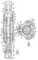
- the body 60 has, on its peripheral surface, notches 65 to allow the passage of the drilling mud outside the stabilizer, on its return to the surface, inside the hole 53.
- the body 60 also includes lights 66 serving as housing for the support blades 68.
- the stabilizer shown in FIGS. 4 and 5 comprises three support blades 68 arranged in openings 66 placed at 120 ° around the body of the stabilizer.
- Leaf springs 71 one end of which is fixed by screws to the body 70 are supported by their other end on the terminal parts of the leaves 68 so as to keep them in the retracted position in the radial direction as shown in FIGS. 4 and 5.
- a play is reserved for mounting between the spring leaf 71 and the closing part 72 in order to allow a certain movement of the support leaf in the radial direction, between its complete retraction position shown in FIGS. 4 and 5 and an extraction position or exit position of the support blade 68, under the effect of a pair of actuating fingers 69 mounted movable in the radial direction inside the body 60.
- Each of the fingers 69 is mounted mobile and leaktight in the body 60 by virtue of a seal ring 70.
- a tubular piston 75 comprising, to allow its mounting, two parts 75a and 75b tightly assembled together by means of a thread 76 and a seal 77.
- the piston 75 is slidably mounted in the bore 63 by means of a part of its peripheral surface and two seals - sealing rings 78 placed at its ends.
- a ball stop 80 on which bears the end of a helical spring 81, the other end of which is resting on a stop 82 fixed on the body 60, inside the bore 63.
- a profiled annular part 84 is also mounted inside the part 75b of the piston 75, at its end corresponding to the inlet drilling fluid flowing in the direction of arrow 64.
- a second profiled part 85 or needle is disposed inside the body 60 along the axis 62 of the bore 63 of this body 60.
- the needle 85 is fixed in the body 60 by means of an annular support piece 86 comprising radial spacers 87 for fixing the needle 85.
- the drilling fluid circulating in the direction and direction of the arrow 64 undergoes a pressure drop which is a function of its flow rate, when it penetrates inside the piston 75 via the profiled inlet 84.
- the pressure difference on either side of the piston 75 becomes sufficient to exert on this piston a force greater than the force of the spring 81, so that the piston 75 begins to move axially in the direction of the arrow 64.
- the internal profile of the part 84 cooperates with the external profile of the needle 85 to progressively decrease the cross-section of the fluid and correlatively increase the pressure drop.
- the pressure drop becomes very high and corresponds to a value which can be easily identified at the pumping installation, thanks to the pressure measurement device 56 associated with this pumping installation 55.
- displacement of the piston 75 is therefore controlled by the flow rate of the pumping fluid and perfectly controlled from the surface by a pressure measurement.
- Such a remote actuation device has great stability since the pressure drop generating the displacement force of the piston increases continuously during the displacement of this piston.
- actuated ramps constituting two sets 90 and 91 spaced apart longitudinally on the piston 75 and each cooperating with a set of three actuating fingers 69 placed at one of the ends of the blades 68 .
- the ramps 90 and 91 are inclined in the same direction, in the radial direction, relative to the axis 62 common to the piston 75 and to the bore 63. This inclination makes it possible to move the blades radially during the axial displacement of the following piston the direction of the arrow 64.
- successive inclined ramps 90a, 90b, 90c are arranged one after the other on the piston 75, along its periphery.
- a complete cycle of movement of a blade 68 is obtained by the three successive inclined ramps 90a, 90b and 90c whose machining depths at their ends and from the outside diameter of the piston 75 are indicated (in 10- 3 m) in fig. 6.
- Each of the fingers 69 is held, by the springs 71 of the corresponding blade 68, in contact with the bottom of a ramp 90, by means of an end part machined in the form of a spherical seat. .
- the displacement of the piston in the direction of the arrow 93 makes it possible to pass the end of the finger 69 from the level -11 to the level -6, by interaction of this finger 69 with the ramp 90a.
- the ramp 90b allows the finger to pass from level -6 to level -4.5.
- the distribution of the ramps along the periphery of the piston 75 is such that at all times, all of the fingers 69 come into contact with a set of identical ramps and the displacements, in the radial direction, of these fingers are therefore identical at all times.
- the ramp 90c corresponds to a passage of the fingers 69 from the level -4.5 to the level -11, which corresponds to a return of the fingers 69 to their initial position and to a return of the blades 68 in their retracted position.
- Each of the three fingers 69 of the assembly shown in FIG. 5 therefore performs a complete movement cycle with three ramps 90a, 90b and 90c.
- the ramps 90a, 90b and 90c are interconnected by curved parts 94 and by straight parts 95 at constant level, to form a continuous actuation surface 96 arranged at the periphery of the piston 75.
- the curved parts 95 joining the end of the ramps 90 to the end of the straight parts 95 allow the piston 75 to rotate, step by step in the direction of the arrow 98, by interaction of the end of the finger 69 with the curved part 94 , at the end of movement of the piston 75 in one direction or the other.
- the driving force is provided by the pressure drop of the drilling fluid and in the other by the energy stored by the spring 81.
- the stepwise rotation movement of the piston can only occur in the direction of arrow 98, a free wheel 100 (FIG. 4) being mounted in the bore 63 of the body 60 around the part 75b of the piston 75.
- the piston is made integral in rotation with this free wheel by means of a key engaged in a longitudinal groove 101 machined on the part 75b of the piston.
- the piston 75 can thus move longitudinally relative to the free wheel 100 to effect its back-and-forth movements under the action of the fluid and under the action of the spring 81.
- Each of the longitudinal displacements of the piston in the direction of arrow 64 by action of the drilling fluid in circulation, therefore results in a radial movement of the blades in the direction of extraction (two successive steps) and in the direction of retraction (one step of longitudinal displacement).
- longitudinal displacement steps of the piston By recording the longitudinal displacement steps of the piston from the surface, we therefore arrive at a precise knowledge of the position of the blades, which makes it possible to achieve very good control of the stabilizer.
- This recording of the steps, as indicated, is extremely easy since the end of each of the piston motor movements in the longitudinal direction results in a large increase in pumping pressure.
- the operating mode of the device is as follows:
- a flow is sent at least equal to the actuation flow of the device in the drill string, which produces the displacement of the piston and the automatic and progressive increase in the pressure drop until the piston arrives at its extreme position, the pressure drop then being maximum.
- the recording of the pressure from the surface makes it possible to determine the end of a step of displacement of the piston. If the output amplitude of the blades is sufficient, the device is automatically held in position as long as the drilling fluid supply flow is not canceled. If it is desired to take an additional step to produce an additional output from the blades, the flow rate of drilling fluid supply is canceled and the piston returns to its initial position by the action of the spring 81.
- a rotation of 20 ° of the piston has enabled finger 69 to be placed on a flat part 95 of the actuating surface 96.
- the curved part 94 of the actuating surface 96 allows a new rotation of 20 ° of the piston in the desired direction thanks to the freewheel 100, so that the finger 69 is in alignment with the next ramp 90b.
- a displacement of the piston 75 is produced in the direction of the arrow 93, the fingers 69 and the blades 68 being moved an additional step towards the outside and in the radial direction. It is obvious that the system can be reset by successive passages of the fingers 69 on the flat part 95 at level -4.5 and on the ramp 90c.
- this actuating device does not require remote control means, its implementation and control being carried out using the pumping and measuring means normally associated with the very long conduit; this actuation device is particularly simple and very reliable; its operation is carried out by very simple and easily controllable operations; it does not require the use of any element in addition to those which are in the conduit at the time of its installation.
- the actuating device is used to control a stabilization device
- the successive displacements of the support blades in one direction and in the other are perfectly controlled and occur under very good conditions of stability.
- the device is also relatively small in size despite its many possibilities.
- the piston and the profiled elements associated with it can have a shape different from those which have been described.
- the first profiled element can be associated with the piston or, on the contrary, independent of this piston. This first profiled element can be separate or confused with the second profiled element.
- the shape of these profiled elements can be different from the shapes which have been described.
- the piston return means may be different from a mechanical spring.
- the receiving member of the driving force of the piston or of the pressure difference provided on the equipment can have any form allowing this driving force to be transmitted to the active elements of the equipment.
- the operating cycle of the tool may be different from that which has been described, in particular the phase preceding the rapid displacement of the piston corresponding to a large increase in the pressure drop can be accompanied by an extremely low pressure drop , which makes it possible to separate the inactive phase from the active phase of the equipment.
- the number of different successive ramps constituting a set of ramps can be different from three if it is desired to move with a succession of steps less than or greater than three.
- Blades can be used arranged in the direction of the axis of the drill string or blades inclined with respect to this axis.
- the number of ramps arranged at the periphery of the actuating piston will be equal to the number of blades multiplied by the number of different steps of displacement of the blades in the radial direction.
- a means other than a freewheel can be associated with the piston to prevent it from rotating. in one direction and to authorize it in the other direction.
- the drilling device according to the invention may include any number of stabilizers each comprising any number of blades, at least one blade of which is radially movable.
- the actuated equipment can consist not only of devices for orienting a drilling tool or devices for stabilizing a drill string, but also devices for perforating a casing, or swelling of waterproofing membranes in a well or borehole using overpressure due to pressure drop.
- the actuation device according to the invention can be applied to any equipment used in the field of drilling or petroleum exploitation or in other fields where very long conduits are used which are hardly or not accessible, for the distribution of an incompressible fluid.
- the invention applies in particular in the case of water distribution or in the case of irrigation, the equipment associated with the conduit then being a multi-way valve making it possible to pass the water distributed from a leads to another.
- This maneuver is carried out very simply by increasing the flow rate of the water to a level higher than the service flow rate then by decreasing this flow rate to a very low or zero level to then raise it to the level corresponding to the service flow rate.
- the reverse operation can obviously be carried out then by increasing the flow again beyond the service flow up to the actuation value.
- the invention applies very generally in all cases where a fluid is used as the working fluid in pipes of great length and at least partially inaccessible and also in all cases of the distribution of fluid by pipes of great length with inaccessible parts.
Landscapes
- Engineering & Computer Science (AREA)
- Life Sciences & Earth Sciences (AREA)
- Geology (AREA)
- Mining & Mineral Resources (AREA)
- Physics & Mathematics (AREA)
- Environmental & Geological Engineering (AREA)
- Fluid Mechanics (AREA)
- General Life Sciences & Earth Sciences (AREA)
- Geochemistry & Mineralogy (AREA)
- Mechanical Engineering (AREA)
- General Engineering & Computer Science (AREA)
- Earth Drilling (AREA)
- Credit Cards Or The Like (AREA)
- Cameras Adapted For Combination With Other Photographic Or Optical Apparatuses (AREA)
- Photographic Developing Apparatuses (AREA)
- Portable Nailing Machines And Staplers (AREA)
- Vehicle Body Suspensions (AREA)
- Radar Systems Or Details Thereof (AREA)
- Replacement Of Web Rolls (AREA)
- Investigating Or Analyzing Materials By The Use Of Ultrasonic Waves (AREA)
- Combined Means For Separation Of Solids (AREA)
- Soil Working Implements (AREA)
Abstract
Description
L'invention concerne de manière générale un dispositif d'actionnement à distance d'un équipement associé à un conduit dans lequel circule un fluide incompressible et plus particulièrement un dispositif d'actionnement d'un stabilisateur d'un train de tiges de forage.The invention relates generally to a device for the remote actuation of equipment associated with a conduit in which an incompressible fluid circulates and more particularly to a device for actuating a stabilizer of a drill string.
Dans le domaine de la recherche et de l'exploitation des hydrocarbures, on utilise des outillages qui doivent développer de fortes puissances pour réaliser des opérations telles que le forage et qui sont situés en fond de trou à une très grande distance de l'endroit situé en surface où sont disposés les moyens de commande et de production de l'énergie nécessaire pour la mise en oeuvre des outillages. Ces outillages en fond de trou sont généralement alimentés en fluide incompressible tel qu'une boue de forage par l'intermédiaire d'un conduit de très grande longueur dont une extrémité se trouve en surface et dont l'autre extrémité est en fond de trou et permet l'alimentation de l'au- til en boue de forage. L'extrémité du conduit située en surface est reliée à une installation de pompage qui permet d'envoyer dans le conduit de la boue de forage sous pression avec un certain débit pratiquement constant pendant le fonctionnement de l'outillage.In the field of research and exploitation of hydrocarbons, tools are used which must develop high powers to carry out operations such as drilling and which are located at the bottom of the hole at a very great distance from the place located at the surface where the means for controlling and producing the energy necessary for the implementation of the tools are arranged. These downhole tools are generally supplied with incompressible fluid such as a drilling mud via a very long pipe, one end of which is at the surface and the other end of which is at the bottom of the hole and allows the supply of drilling mud to the tool. The end of the pipe located on the surface is connected to a pumping installation which makes it possible to send drilling mud into the pipe under pressure with a certain practically constant flow during the operation of the tooling.
Certains équipements associés au conduit ou à la tige de forage et situés à une très grande distance de la surface doivent être télécommandés, et contrôlés par des dispositifs de télémesure. Il en est ainsi par exemple des dispositifs permettant l'orientation de l'outil de forage et son contrôle de trajectoire, dans le cas de forages inclinés.Certain equipment associated with the pipe or the drill pipe and located at a very great distance from the surface must be remote-controlled, and controlled by telemetry devices. This is the case, for example, with devices allowing the orientation of the drilling tool and its trajectory control, in the case of inclined drilling.
Il est également souhaitable de disposer d'un moyen d'actionnement à distance sûr et précis, dans le cas des dispositifs stabilisateurs utilisés dans les installations de forage à trajectoire contrôlée.It is also desirable to have a safe and precise means of remote actuation, in the case of stabilizing devices used in drilling installations with controlled trajectory.
Pour corriger la trajectoire du forage en cours d'avancement afin de contrôler parfaitement sa direction, il estconnu d'utiliser des dispositifs de stabilisation ou stabilisateurs reliés au train de tiges, généralement dans sa partie voisine de l'outil. De tels dispositifs stabilisateurs comportent un corps relié au train de tiges et une ou plusieurs lames susceptibles de se déplacer dans la direction radiale par rapport à l'axe du train de tiges. Un moyen de commande permet d'assurer l'extraction des lames vers l'extérieur du corps du stabilisateur afin de faire varier la distance d'appui entre l'axe du train de tiges et les bords du trou foré. Grâce à ces lames d'appui, on peut suivant les cas (forage vertical, forage incliné de direction constante ou changement de direction de forage) modifier les forces radiales s'exerçant sur le train de tiges et par conséquent sur l'outil en cours de forage, dans le sens voulu.To correct the trajectory of the drilling during advancement in order to perfectly control its direction, it is known to use stabilization devices or stabilizers connected to the drill string, generally in its part adjacent to the tool. Such stabilizing devices comprise a body connected to the drill string and one or more blades capable of moving in the radial direction relative to the axis of the drill string. A control means ensures the extraction of the blades towards the outside of the stabilizer body in order to vary the support distance between the axis of the drill string and the edges of the drilled hole. Thanks to these support blades, it is possible, depending on the case (vertical drilling, inclined drilling of constant direction or change of drilling direction) to modify the radial forces exerted on the drill string and consequently on the tool in progress drilling, in the desired direction.
Cependant, les moyens de commande permettant l'actionnement des stabilisateurs connus actuellement ont une structure complexe, sont d'une utilisation difficile et ne permettent pas d'assurer des déplacements précis et parfaitement contrôlés des lames d'appui.However, the control means allowing the actuation of the currently known stabilizers have a complex structure, are difficult to use and do not allow precise and perfectly controlled movements of the support blades.
De manière générale, on ne connaissait pas jusqu'ici de dispositif simple et de fonctionnement parfaitement sûr permettant d'actionner à distance un équipement associé à un conduit dans lequel circule un fluide sous pression et de contrôler la mise en oeuvre de cet équipement, tout en restant compatible avec les dispositifs de télémesure associés et placés à proximité de l'équipement.In general, hitherto no simple device has been known which is perfectly safe to operate enabling equipment associated with a pipe in which a pressurized fluid circulates to be controlled remotely and controlling the implementation of this equipment, while by remaining compatible with the associated telemetry devices and placed near the equipment.
Le but de l'invention est de proposer un dispositif d'actionnement à distance d'un équipement associé à un conduit ayant une première extrémité par laquelle on envoie un fluide incompressible grâce à des moyens de pompage, avec un débit de service déterminé et une seconde extrémité éloignée de la première où le fluide incompressible est utilisé, par exemple, comme fluide moteur, dispositif d'actionnement qui soit d'une structure simple et d'un fonctionnement sûr, qui puisse être mis en oeuvre sans utiliser de source d'énergie autre que celle fournie par le fluide incompressible et d'éléments d'actionnement extérieurs au conduit et dont le fonctionnement puisse être contrôlé.The object of the invention is to propose a device for the remote actuation of equipment associated with a conduit having a first end through which an incompressible fluid is sent by means of pumping, with a determined service flow and a second end remote from the first where the incompressible fluid is used, for example, as a working fluid, actuation device which is of a simple structure and of safe operation, which can be implemented without using a source of energy other than that supplied by the incompressible fluid and actuating elements external to the duct and the operation of which can be controlled.
Dans ce but, le dispositif d'actionnement suivant l'invention comporte, à l'intérieur du conduit, dans une zone éloignée de la première extrémité :
- - un premier élément profilé d'étranglement limitant ta section de passage du fluide et créant une perte de charge variable en fonction du débit du fluide,
- - un piston différentiel monté mobile dans la direction axiale à l'intérieur du conduit, soumis d'un côté à la pression du fluide en amont du premier élément d'étranglement et de l'autre côté à la pression du fluide réduite par le premier élément d'étranglement profilé,
- - une surface profilée prévue sur le piston et un second élément profilé d'étranglement solidaire du conduit, destinés à coopérer entre eux pour limiter le passage de fluide et augmenter la perte de charge de façon très importante de part et d'autre du piston, lors du déplacement de celui-ci dans un premier sens de déplacement,
- - un moyen de rappel du piston dans son second sens de déplacement opposé au premier,
- - un moyen de détermination des phases d'actionnement par mesure de pression au niveau de la première extrémité du conduit, et
- - un organe récepteur sur l'équipement actionné par le piston ou la différence de pression de part et d'autre du piston, la force du moyen de rappel et le premier élément d'étranglement étant prévus pour que le piston commence à se déplacer dans le premier sens de déplacement pour un débit d'actionnement supérieur au débit de service du fluide dans le conduit.
- - a first profiled throttling element limiting your fluid passage section and creating a variable pressure drop as a function of the fluid flow rate,
- - a differential piston mounted movable in the axial direction inside the conduit, subjected on one side to the fluid pressure upstream of the first throttling element and on the other side to the fluid pressure reduced by the first streamlined choke element,
- a profiled surface provided on the piston and a second profiled choke element integral with the duct, intended to cooperate with each other to limit the passage of fluid and to increase the pressure drop very significantly on either side of the piston, when moving it in a first direction of movement,
- a means for returning the piston to its second direction of movement opposite to the first,
- a means for determining the actuation phases by measuring the pressure at the first end of the conduit, and
- - a receiving member on the equipment actuated by the piston or the pressure difference on either side of the piston, the force of the return means and the first throttling element being provided so that the piston begins to move in the first direction of movement for an actuating flow rate greater than the service flow rate of the fluid in the duct.
Dans le cas où le conduit est un train de tiges creuses d'un dispositif de forage à trajectoire contrôlée portant un outil de forage fixé à l'une de ses extrémités, l'équipement actionné par le piston étant un dispositif de stabilisation comportant un corps relié au train de tiges et au moins une lame d'appui montée mobile radialement dans le corps, le piston du dispositif d'actionnement est monté mobile dans t'atésage central du corps, non seulement en translation mais aussi en rotation autour de l'axe du train de tiges et il comporte, sur sa surface latérale externe, des rampes longitudinales, inclinées dans une direction radiale par rapport à l'axe des tiges, placées les unes à la suite des autres suivant la périphérie du piston et reliées entre elles pour constituer une surface d'actionnement continue par des parties complémentaires de guidage pour le déplacement en rotation pas à pas du piston et pour son retour à sa position initiale, au moins un doigt d'actionnement monté mobile radialement dans le corps coopérant avec la surface d'actionnement continue d'une part et la lame d'autre part pour son extraction radiale, lors du déplacement du piston, dans un premier sens de déplacement qui s'accompagne d'une perte de charge très fortement accrue, dans le fluide de forage en circulation, en fin de mouvement d'actionnement du piston.In the case where the conduit is a train of hollow rods of a drilling device with controlled trajectory carrying a drilling tool fixed at one of its ends, the equipment actuated by the piston being a stabilization device comprising a body connected to the drill string and at least one support blade mounted to move radially in the body, the piston of the actuating device is mounted to move in the central bore of the body, not only in translation but also in rotation around of the axis of the drill string and it has, on its external lateral surface, longitudinal ramps, inclined in a radial direction relative to the axis of the rods, placed one after the other along the periphery of the piston and connected together to form a continuous actuation surface by complementary guide parts for the stepwise rotation of the piston and for its return to its initial position, at least one actuation finger mounted to move radially in the cooperating body with the continuous actuating surface on the one hand and the blade on the other hand for its radial extraction, during the displacement of the piston, in a first direction of displacement which is accompanied by a very greatly increased pressure drop, in the drilling fluid in circulation, at the end of the piston actuation movement.
Afin de bien faire comprendre l'invention, on va maintenant décrire, à titre d'exemples non limitatifs, en se référant aux figures jointes en annexe, plusieurs modes de réalisation d'un dispositif d'actionnement suivant l'invention utilisé dans le domaine du forage et de l'exploitation pétrolière.In order to clearly understand the invention, we will now describe, by way of nonlimiting examples, with reference to the attached figures, several embodiments of an actuation device according to the invention used in the field oil drilling and exploitation.
Dans ces figures:
- la fig. 1 est une vue schématique d'une installation de forage comportant un équipement qui peut être actionné par un dispositif selon l'invention,
- les fig. 1 a, 1 b, 1 c et 1 d sont des vues en coupe longitudinale d'un dispositif d'actionnement suivant l'invention etsuivantquatre modes de réalisation différents,
- la fig. 2 est un diagramme de fonctionnement du dispositif représenté à la fig. 1 a, montrant les variations au cours du temps, pendant un cycle de fonctionnement du dispositif, de divers paramètres caractéristiques,
- la fig. 3 est une vue schématique d'ensemble d'un dispositif de forage à trajectoire contrôlée comportant des stabilisateurs commandés par un dispositif d'actionnement suivant l'invention,
- la fig. 4 est une vue en coupe longitudinale, suivant IV-IV de la fig. 5, d'un stabilisateur du dispositif de forage représenté sur la fig. 3,
- la fig. 5 est une vue en coupe, suivant V-V de la fig. 4, du stabilisateur,
- la fig. 6 est une vue développée de la surface d'actionnement, des lames et du piston du stabilisateur.
- fig. 1 is a schematic view of a drilling installation comprising equipment which can be actuated by a device according to the invention,
- fig. 1 a, 1 b, 1 c and 1 d are views in longitudinal section of an actuating device according to the invention and according to four different embodiments,
- fig. 2 is an operating diagram of the device shown in FIG. 1 a, showing the variations over time, during an operating cycle of the device, of various characteristic parameters,
- fig. 3 is a schematic overview of a drilling device with a controlled trajectory comprising stabilizers controlled by an actuating device according to the invention,
- fig. 4 is a view in longitudinal section, along IV-IV of FIG. 5, a stabilizer of the drilling device shown in FIG. 3,
- fig. 5 is a sectional view, along VV of FIG. 4, of the stabilizer,
- fig. 6 is a developed view of the actuating surface, the blades and the piston of the stabilizer.
Sur la fig.1, on voit une installation de forage qui comporte un train de tiges 1 portant à son extrémité inférieure l'outil de forage 2. L'outil 2 a été représenté en position de travail au fond du trou 3. Le train de tiges creuses 1 constitue un conduit de grande longueur dont une extrémité est reliée à l'outil 2 en fond de trou et dont l'autre extrémité qui se trouve en surface est reliée à un conduit 4 permettant l'injection de boue de forage à haute pression et à débit constant dans l'espace intérieur des tiges 1. Pour cela, le conduit 4 est relié à une installation de pompage 5 sur laquelle un dispositif de mesure 6 permet de déterminer de façon précise la pression de pompage. La boue de forage descend dans le train de tiges, alimente l'outil 2 en fond de trou et remonte à la surface par le trou 3, à l'extérieur du train de tiges 1. Un équipement 7 d'orientation de l'outil 2 et un ensemble de télémesure 8 sont associés au train de tiges 1, au-dessus de la partie de jonction de l'outil 2 au train de tiges. La boue de forage sous pression est utilisée comme fluide moteur de l'outil de forage 2.In fig.1, we see a drilling installation which includes a drill string 1 carrying at its lower end the
Sur la fig. 1 a, on voit un mode de réalisation d'un dispositif d'actionnement suivant l'invention permettant de mettre en oeuvre un équipement tel que l'équipement 7 d'orientation d'un outil de forage, à distance, en lui fournissant la puissance motrice nécessaire. Ce dispositif est placé dans une partie 11 du conduit de grande longueur constitué par le train de tiges. Cette partie 11 peut elle-même être constituée par une pièce de raccord entre les tiges, une partie d'extrémité d'une tige ou encore une partie de l'équipement 7 raccordable au train de tiges. Cette partie 11 creuse reçoit dans son alésage central 12 le flux de boue de forage qui circule suivant la direction des flèches 13 pour parvenir à l'outil 2 en fond de trou. L'alésage 12 de la partie 11 du train de tiges comporte une partie élargie 12a à l'intérieur de laquelle est monté le dispositif d'actionnement. Ce dispositif comporte un piston différentiel 10 de forme tubulaire et profilée, un ressort de rappel 15 et un élément profilé 16 disposé axialement dans le conduit 11.In fig. 1a, an embodiment of an actuating device according to the invention is seen, making it possible to implement equipment such as the
L'alésage intérieur du piston 10 comporte deux parties successives dans le sens 13 de circulation de la boue de forage, une première partie profilée 17 constituant un diaphragme introduisant une perte de charge dans le conduit et une seconde partie profilée 18 de forme tronconique comportant une partie d'étranglement 18a à son extrémité et reliée au diaphragme 17 par l'intermédiaire d'une surface torique. Cette surface profilée 18 peut être également de forme cylindrique. L'élément profilé 16 ou aiguille comporte une partie antérieure 16a en forme d'ogive et une partie postérieure 16b permettant sa fixation à l'intérieur du conduit 11 par l'intermédiaire d'entretoises 20. L'aiguille est percée d'un alésage central 19. Dans d'autres variantes de réalisation du dispositif, cette aiguille 16 peut être réalisée sans perçage central.The internal bore of the
Le piston 10 est monté étanche parl'intermédiaire d'un jeu de joints segments 22 dans la partie 12a de l'alésage du conduit constituant la chambre du piston 10. A sa partie antérieure, le piston 10 est prolongé par une partie de guidage 23 montée glissante et de façon parfaitement guidée à l'intérieur d'ouvertures usinées dans la partie 11 du conduit. D'autres liaisons mécaniques peuvent être réalisées entre la partie 11 du conduit et le piston 10. Le piston 10 est rappelé dans sa position avant, comme représenté sur la fig. 1 a, par un ressort 15 dont la force est prévue pour maintenir le piston dans cette position avant lorsque la boue de forage circule dans le conduit à son débit normal ou débitde service inférieur au débit de commande du dispositif d'actionnement.The
La forme de la partie antérieure profilée 16a de l'élément 16 est prévue pour coopérer avec le profil 18 du piston pour créer une perte de charge importante sur la circulation de la boue de forage, lorsque le piston se déplace vers l'arrière, c'est-à-dire de la gauche vers la droite sur la fig. 1 a. Cette perte de charge due à la coopération des éléments profilés 16 et 18 augmente, de façon importante et très rapidement, la perte de charge totale du dispositif.The shape of the profiled
Sur la fig. 2, on voit un diagramme de fonctionnement du dispositif représenté sur la fig. 1 a, le temps étant porté en abscisse, le débit 0 de la boue de forage, la perte de charge A P à travers le dispositif d'actionnement et la course du piston différentiel 10, en ordonnée. La variation au cours du temps du débit Q, lors d'un cycle de fonctionnement du dispositif d'actionnement, a été représentée par la courbe 25 en pointillés, la variation de la perte de charge Δ P par la courbe 26 en traits pleins et la variation de la course C du piston 10 par la courbe en traits mixtes 27.In fig. 2, we can see an operating diagram of the device shown in FIG. 1 a, time being plotted on the abscissa, the
L'origine du diagramme représente le point de fonctionnement au débit de service QS de la boue de forage et à déplacement nul du piston 10.The origin of the diagram represents the operating point at the QS service flow rate of the drilling mud and at zero displacement of the
Pour mettre en oeuvre le dispositif d'actionnement, on augmente progressivement le débit de la boue de forage pendant la première période TA du cycle d'actionnement, pour amener ce débit de la valeur O ou OS à une valeur QACT ou débit d'actionnement. A la fin de cette partie du cycle, la perte de charge dans la partie antérieure profilée 17 du piston 10 atteint une valeur Δ Pa telle que la surpression sur la face antérieure du piston crée une force qui commence à dépasser la force de rappel du ressort. Le piston se déplace alors vers l'arrière, pour effectuer une course C1, le débit étant maintenu à la valeur QACT. La perte de charge augmente lentement de la valeur A Pa à la valeur A Pb, par diminution lente de la section de sortie du piston 10 pendant la seconde phase B du cycle de fonctionnement. La course C1 du piston 10 a alors amené son profil 18 en vis-à-vis du profil 16a de l'aiguille 16. La perte de charge A P augmente très rapidement et le piston se déplace vers l'arrière à vitesse accrue pendant la phase C du cycle de fonctionnement. Le débit est maintenu à la valeur QACT grâce à l'installation de pompage 5, le déplacement du piston est auto-entretenu par l'augmentation de la perte de charge et le piston 10 se déplace jusqu'à venir en butée sur la partie arrière de sa chambre 12a en effectuant la course C2. La perte de charge passe alors de la valeur A Pb à sa valeur maximale A Pm. Cette augmentation de la perte de charge est considérablement plus forte que celle qui pourrait être obtenue par une augmentation du débit dans un diaphragme dont l'ouverture est constante.To implement the actuation device, the flow of drilling mud is gradually increased during the first period T A of the actuation cycle, to bring this flow from the value O or OS to a value Q ACT or flow d actuation. At the end of this part of the cycle, the pressure drop in the profiled
La partie antérieure 23 du piston est reliée à un organe mobile de l'équipement 7 pour donner un angle d'orientation à l'outil 2.The
Simultanément ou indépendamment, on peut également utiliser la surpression Δ P de la boue de forage prélevée par des conduits 24 à l'avant du piston 10, pour actionner un organe récepteur hydraulique de l'équipement 7. Si, au cours de la manoeuvre de l'équipement 7, au débit constant QACT, la force exercée par le piston 10 devient insuffisante pour continuer à effectuer la manoeuvre, la perte de charge n'augmente plus. On enregistre un palier à une valeur A Pi < Δ Pm. Il suffit alors de porter le débit à une valeur QACT supérieure à QACT pour terminer la manoeuvre de l'équipement 7. La perte de charge maximale s'établit à une valeur Δ' Pm > Δ Pm. On peut ensuite ramener et maintenir le débit à la valeur QACT qui est suffisante pour assurer le maintien du piston 10 en position arrière.Simultaneously or independently, it is also possible to use the overpressure Δ P of the drilling mud collected by
Tant que le débit est maintenu à la valeur QACT, le piston différentiel 10 reste dans sa position arrière et la perte de charge Δ P à sa valeur maximale.As long as the flow is maintained at the value Q ACT, the
On obtient le retour du piston à sa position avant représentée sur la fig. 1 a, en diminuant progressivement le débit pour le ramener à la valeur 0 (phase E ). On peut faire fonctionner ensuite l'outil 2 en augmentant le débit à la valeur du débit de service Qs et avec la nouvelle position de l'équipement associé au dispositif d'actionnement.The piston is returned to its front position shown in fig. 1 a, gradually decreasing the flow to bring it back to the value 0 (phase E).
Pendant tout le cycle de fonctionnement, l'augmentation puis le maintien du débit à QACT sont obtenus par l'installation de pompage 5 et les variations de pression de pompage Δ P sont repérées et enregistrées grâce à l'appareil de mesure 6. Aussi bien la commande que le contrôle du cycle de fonctionnement sont donc effectués sans difficultés depuis la surface sans utiliser de dispositif de télécommande. En particulier, on peut enregistrer facilement et repérer un arrêt du piston avant la fin de la manoeuvre qui se traduit par un palier de pression. On obtient alors la poursuite de la ma- nœuvre en augmentant le débit jusqu'à une valeur suffisante pour assurer le déblocage de l'équipement. Les moyens de pompage 5 doivent donc permettre de monter le débit à des valeurs supérieures à QACT, en cas de besoin. De façon générale, pendant tout le cycle de fonctionnement du dispositif, l'enregistrement de la surpression correspondant à la perte de charge Δ P, en fonction du temps, permet de connaître la position du piston 10 et donc de contrôler l'actionnement du dispositif. On associe donc au dispositif de mesure 6 un enregistreur de la pression en fonction du temps.During the entire operating cycle, the increase and then the maintenance of the flow rate at Q ACT are obtained by the pumping
Pour obtenir un retour du piston dans sa position initiale, après actionnement de l'équipement, il peut être seulement nécessaire de diminuer le débit de pompage jusqu'à une valeur non nulle, inférieure à Qs. On peut ensuite faire fonctionner l'outil 2 en augmentant à nouveau ce débit jusqu'à la valeur Qs.To obtain a return of the piston to its initial position, after actuation of the equipment, it may only be necessary to reduce the pumping rate to a non-zero value, less than Q s .
Sur les fig. 1 b, 1 c et 1 d, on a représenté des variantes de réalisation du dispositif d'actionnement. Les éléments correspondants sur les fig. 1 à à 1 d portent les mêmes repères.In fig. 1b, 1c and 1d, there are shown alternative embodiments of the actuating device. The corresponding elements in fig. 1 to 1 d have the same references.
Sur la fig. 1 b, on voit que le piston 10 est cette fois constitué par une pièce pleine comportant une partie profilée 31 destinée à coopérer avec un élément profilé 30 usiné sur la surface intérieure du conduit 11. Cet élément 30 joue à la fois le rôle du diaphragme 17 et de l'aiguille 16 du mode de réalisation représenté sur la fig. 1 a. Le piston 10 comporte une partie cylindrique 10a munie d'un joint segment monté mobile à l'intérieur d'une chambre prévue dans un cylindre 35 monté suivant l'axe du conduit 11. La chambre du piston 10 reçoit à l'une de ses extrémités un fluide hydraulique par l'intermédiaire de canalisations 34 communiquant à leur autre extrémité avec une chambre annulaire 33 coaxiale au conduit et fermée par une membrane cylindrique souple 32. Le fluide hydraulique agissant dans la chambre du piston et en contact avec sa face avant est en équilibre de pression avec la boue de forage en amont du dispositif d'actionnement. La face arrière du piston est en revanche en contact avec la boue de forage à une pression diminuée de la perte de charge introduite par l'élément profilé 30.In fig. 1b, it can be seen that the
L'ensemble piston 10 et ressort 15 est monté étanche à l'intérieur de la chambre du cylindre 35 recevant un fluide hydraulique non pollué par la boue de forage.The
Le fonctionnement du dispositif est pratiquement identique au fonctionnement du dispositif représenté sur la fig. 1 a, la perte de charge A P introduite par l'élément 30 devenant suffisante dès que le débit atteint la valeur QACr, pour que le piston se déplace dans le sens d'écoulement (flèche 13). La coopération de la partie 31 du piston et de l'élément 30 augmente alors la perte de charge de façon que le piston se déplace jusqu'à sa position extrême.The operation of the device is practically identical to the operation of the device shown in FIG. 1 a, the pressure drop A P introduced by the
Comme précédemment, la boue de forage en surpression est récupérée par des conduits 24 pour l'actionnement de l'équipement 7 associé au conduit.As before, the overpressured drilling mud is recovered by
Sur la fig. 1 c, on voit un mode de réalisation du dispositif associant des éléments identiques à ceux du dispositif de la fig. 1 b, mais dans une disposition différente. Le cylindre 35 et la chambre du piston 10 sont orientés en sens inverse, par rapport à la circulation de la boue de forage (flèche 13). Un circuit fermé comportant la chambre annulaire 33, les conduits 34 et la chambre du piston 10 renferme un fluide hydraulique totalement isolé de la boue de forage et l'élément profilé 30 du conduit introduit une perte de charge qui permet l'amorçage du mouvement du piston lorsque le débit atteint la valeur QACT. La partie profilée 31 du piston coopère alors avec l'élément 30 qui joue le rôle à la fois du diaphragme 17 et de l'aiguille 16 du mode de réalisation de la fig. 1a.In fig. 1 c, an embodiment of the device is seen associating elements identical to those of the device of FIG. 1 b, but in a different provision. The
Comme précédemment, la surpression A P est récupérée par des conduits 24 pour l'actionnement de l'équipement 7.As before, the overpressure A P is recovered by
Dans le mode de réalisation représenté à la fig. 1 d, le piston 10 a une forme tubulaire et un double profil 17, 18 comme le piston représenté sur la fig. 1a.In the embodiment shown in FIG. 1d, the
Le profil tronconique 18 coopère avec un organe 36 de fermeture progressive d'un conduit 37 fixé de façon coaxiale à l'intérieur du conduit 11 grâce à des entretoises 38 permettant la fixation du conduit 37 et de l'élément d'obturation 36.The frusto-
Dès que le débit atteint la valeur QACT' le piston se déplace vers l'arrière et le profil 18 referme l'élément déformable 36 en augmentant la perte de charge, si bien que le piston 10 se déplace jusqu'à sa position extrême en butée arrière.As soon as the flow reaches the value Q ACT ′ the piston moves backwards and the
Dans les dispositifs représentés aux fig. 1 b, 1 c et 1 d, la remise en position initiale du piston peut être effectuée en ramenant le débit à une valeur faible qui peut être la valeur nulle.In the devices shown in fig. 1 b, 1 c and 1 d, the resetting of the initial position of the piston can be carried out by reducing the flow rate to a low value which may be the zero value.
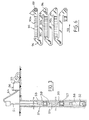
Sur la fig. 3, on voit une installation de forage comportant un train de tiges de forage 51 portant à son extrémité inférieure un outil de forage 52 et relié à son autre extrémité, par un conduit 54, à une installation de pompage 55 permettant l'injection de boue de forage par l'intérieur du train de tiges 51, au niveau de l'outil 52 en position de travail dans le fond du trou 53.In fig. 3, a drilling installation is seen comprising a
Le train de tiges 51 comporte des tiges successives telles que 51 a et 51 b qui sont, comme visible sur la fig. 1, reliées entre elles et à l'outil de forage 52 par des éléments intermédiaires comportant un stabilisateur 57 et des pièces de jonction 59.The
Sur le dispositif de pompage 55 est placé un moyen de mesure 56 de la pression de pompage de la boue de forage.On the
Un ensemble de mesure 58 est associé à l'outil et permet en particulier des mesures d'orientation du train de tiges 51.A measuring
Sur la fig. 4 on voit un dispositif de stabilisation désigné de façon générale par le repère 57 qui comporte un corps 60 de forme générale tubulaire comportant des extrémités 61 a et 61 b taraudées permettant la jonction du stabilisateur 57 au train de tiges ou à l'outil par l'intermédiaire de raccords filetés tels que 59. Lorsque le stabilisateur est relié au train de tiges, l'alésage 63 du corps 60 a son axe 62 commun avec l'axe du train de tiges. La boue de forage circule dans le train de tiges et le stabilisateur suivant la direction axiale, dans le sens de la flèche 64.In fig. 4 we see a stabilization device generally designated by the
Comme il est visible sur les fig. 4 et 5, le corps 60 comporte, sur sa surface périphérique, des échancrures 65 pour permettre le passage de la boue de forage à l'extérieur du stabilisateur, à son retour vers la surface, à l'intérieur du trou 53. Le corps 60 comporte également des lumières 66 servant de logement pour les lames d'appui 68. Le stabilisateur représenté sur les fig. 4 et 5 comporte trois lames d'appui 68 disposées dans des ouvertures 66 placées à 120° autour du corps du stabilisateur. Des ressorts à lame 71 dont une extrémité est fixée par des vis sur le corps 70 sont en appui par leur autre extrémité sur les parties terminales des lames 68 de façon à les maintenir en position rétractée dans la direction radiale comme représenté sur les fig. 4 et 5. Des pièces de fermeture 72 montées dans les parties d'extrémité des ouvertures 66, à l'extérieur des ressorts à lame 71, permettent d'assurer le guidage des lames 68 dans leur direction radiale de déplacement. Un jeu est réservé au montage entre la lame de ressort 71 et la pièce de fermeture 72 afin de permettre un certain débattement de la lame d'appui dans la direction radiale, entre sa position de rétraction complète représentée aux fig. 4 et 5 et une position d'extraction ou position de sortie de la lame d'appui 68, sous l'effet d'une paire de doigts d'actionnement 69 montés mobiles dans la direction radiale à l'intérieur du corps 60. Chacun des doigts 69 est monté mobile et étanche dans le corps 60 grâce à un joint- segment d'étanchéité 70.As can be seen in Figs. 4 and 5, the
A l'intérieur de l'alésage 63 du corps 60 est monté un piston tubulaire 75 comportant, pour permettre son montage, deux parties 75a et 75b assemblées entre elles de façon étanche grâce à un filetage 76 et à un joint 77. Le piston 75 est monté glissant dans l'alésage 63 par l'intermédiaire d'une partie de sa surface périphérique et de deux joints- segments d'étanchéité 78 placés à ses extrémités.Inside the bore 63 of the
A l'extrémité de la partie 75b du piston, à l'intérieur de la partie 75a de ce piston, est disposée une butée à bille 80 sur laquelle vient en appui l'extrémité d'un ressort hélicoïdal 81 dont l'autre extrémité est en appui sur une butée 82 fixée sur le corps 60, à l'intérieur de l'alésage 63. Une pièce annulaire profilée 84 est également montée à l'intérieur de la partie 75b du piston 75, à son extrémité correspondant à l'entrée du fluide de forage circulant suivant le sens de la flèche 64.At the end of
Une seconde pièce profilée 85 ou aiguille est disposée à l'intérieur du corps 60 suivant l'axe 62 de l'alésage 63 de ce corps 60. L'aiguille 85 est fixée dans le corps 60 grâce à une pièce annulaire de support 86 comportant des entretoises radiales 87 pour la fixation de l'aiguille 85.A second profiled
Le fluide de forage circulant suivant le sens et la direction de la flèche 64 subit une perte de charge qui est fonction de son débit, lorsqu'il pénètre à l'intérieur du piston 75 par l'entrée profilée 84. Pour un certain débit, appelé débit d'actionnement, la différence de pression de part et d'autre du piston 75 devient suffisante pour exercer sur ce piston une force supérieure à la force du ressort 81, si bien que le piston 75 commence à se déplacer axialement dans le sens de la flèche 64. Le profil intérieur de la pièce 84 coopère avec le profil extérieur de l'aiguille 85 pour diminuer progressivement la section de passage du fluide et augmenter corrélativement la perte de charge. En fin de mouvement du piston, la perte de charge devient très forte et correspond à une valeur qui peut être facilement repérée au niveau de l'installation de pompage, grâce au dispositif de mesure de pression 56 associé à cette installation de pompage 55. Le déplacement du piston 75 est donc commandé par le débit du fluide de pompage et parfaitement contrôlé depuis la surface par une mesure de pression.The drilling fluid circulating in the direction and direction of the
Un tel dispositif d'actionnement à distance présente une grande stabilité puisque la perte de charge engendrant la force de déplacement du piston augmente continuellement pendant le déplacement de ce piston.Such a remote actuation device has great stability since the pressure drop generating the displacement force of the piston increases continuously during the displacement of this piston.
Sur la surface latérale externe du piston 75 sont usinées des rampes d'actionnement constituant deux jeux 90 et 91 espacés longitudinalement sur le piston 75 et coopérant chacun avec un ensemble de trois doigts d'actionnement 69 placés à l'une des extrémités des lames 68.On the external lateral surface of the
Les rampes 90 et 91 sont inclinées dans le même sens, dans la direction radiale, par rapport à l'axe 62 commun au piston 75 et à l'alésage 63. Cette inclinaison permet de déplacer les lames radialement pendant le déplacement axial du piston suivant le sens de la flèche 64.The
En se reportant aux fig. 5 et 6, on voit que des rampes inclinées successives 90a, 90b, 90c sont disposées les unes à la suite des autres sur le piston 75, suivant sa périphérie. Un cycle complet de déplacement d'une lame 68 est obtenu par les trois rampes inclinées successives 90a, 90b et 90c dont les profondeurs d'usinage à leurs extrémités et à partir du diamètre extérieur du piston 75 sont indiquées (en 10-3 m) sur la fig. 6. Chacun des doigts 69 est maintenu, par les ressorts 71 de la lame 68 correspondante, en contact avec le fond d'une rampe 90, par l'intermédiaire d'une partie d'extrémité usinée sous la forme d'une portée sphérique.Referring to figs. 5 and 6, it can be seen that successive
Comme il est visible sur la fig. 6, le déplacement du piston dans le sens de la flèche 93 permet de faire passer l'extrémité du doigt 69 du niveau -11 au niveau -6, par interaction de ce doigt 69 avec la rampe 90a. De la même façon, la rampe 90b permet de faire passer le doigt du niveau -6 au niveau -4,5. Ces deux déplacements le long des rampes 90a et 90b s'accompagnent donc d'un mouvement radial des doigts 69 vers l'extérieur du corps 70 et donc d'un mouvement des lames 68 vers l'extérieur. En effet, comme il est visible sur la fig. 5, la répartition des rampes suivant la périphérie du piston 75 est telle qu'à chaque instant, l'ensemble des doigts 69 vient en contact avec un ensemble de rampes identiques et que les déplacements, dans la direction radiale, de ces doigts sont donc identiques à tout instant. La rampe 90c correspond à un passage des doigts 69 du niveau -4,5 au niveau -11, ce qui correspond à un retour des doigts 69 à leur position initiale et à un retour des lames 68 dans leur position rétractée.As can be seen in fig. 6, the displacement of the piston in the direction of the
Chacun des trois doigts 69 de l'ensemble représenté à la fig. 5 effectue donc un cycle complet de déplacement avec trois rampes 90a, 90b et 90c. Le nombre total des rampes constituant l'ensemble 90 est donc 3x3=9.Each of the three
On voit sur les fig. 5 et 6 que les rampes 90a, 90b et 90c sont reliées entre elles par des parties courbes 94 et par des parties droites 95 à niveau constant, pour constituer une surface continue d'actionnement 96 disposée à la périphérie du piston 75. Les parties courbes 95 joignant l'extrémité des rampes 90 à l'extrémité des parties droites 95 permettent la mise en rotation du piston 75, pas à pas dans la direction de la flèche 98, par interaction de l'extrémité du doigt 69 avec la partie courbe 94, en fin de mouvement du piston 75 dans un sens ou dans l'autre. Chacun des pas correspond à la distance angulaire entre la rampe 90 et la partie plane 95 voisine, c'est-à-dire 360°/18 = 20°.We see in fig. 5 and 6 that the
Dans un sens la force motrice est procurée par la perte de charge du fluide de forage et dans l'autre par l'énergie emmagasinée par le ressort 81.In one direction the driving force is provided by the pressure drop of the drilling fluid and in the other by the energy stored by the
Le mouvement de rotation pas à pas du piston ne peut se produire que dans le sens de la flèche 98, une roue libre 100 (fig. 4) étant montée dans l'alésage 63 du corps 60 autour de la partie 75b du piston 75. Le piston est rendu solidaire en rotation de cette roue libre par l'intermédiaire d'une clavette engagée dans une rainure longitudinale 101 usinée sur la partie 75b du piston. Le piston 75 peut ainsi se déplacer longitudinalement par rapport à la roue libre 100 pour effectuer ses mouvements de va-et-vient sous l'action du fluide et sous l'action du ressort 81.The stepwise rotation movement of the piston can only occur in the direction of
Chacun des déplacements longitudinaux du piston dans le sens de la flèche 64, par action du fluide de forage en circulation, se traduit donc par un mouvement radial des lames dans le sens de l'extraction (deux pas successifs) et dans le sens de la rétraction (un pas de déplacement longitudinal). En enregistrant depuis la surface les pas de déplacement longitudinal du piston, on arrive donc à connaître de façon précise la position des lames, ce qui permet de réaliser un très bon contrôle du stabilisateur. Cet enregistrement des pas, comme il a été indiqué, est extrêmement facile puisque la fin de chacun des déplacements moteurs du piston dans le sens longitudinal se traduit par une forte augmentation de pression de pompage.Each of the longitudinal displacements of the piston in the direction of
Le mode de fonctionnement du dispositif est le suivant:The operating mode of the device is as follows:
Les lames étant dans leur position rétractée telle que représentée aux fig. 4 et 5, on envoie un débit au moins égal au débit d'actionnement du dispositif dans le train de tiges, ce qui produit le déplacement du piston et l'augmentation automatique et progressive de la perte de charge jusqu'à ce que le piston arrive à sa position extrême, la perte de charge étant alors maximum. L'enregistrement de la pression depuis la surface permet de déterminer la fin d'un pas de déplacement du piston. Si l'amplitude de sortie des lames est suffisante, le dispositif est maintenu automatiquement en position tant que le débit d'alimentation en fluide de forage n'est pas annulé. Si l'on désire effectuer un pas supplémentaire pour réaliser une sortie supplémentaire des lames, on annule le débit d'alimentation en fluide de forage et le piston revient dans sa position initiale par l'action du ressort 81. Entre- temps, une rotation de 20° du piston a permis au doigt 69 d'être placé sur une partie plane 95 de la surface d'actionnement 96. A l'extrémité de la partie plane 95, la partie courbe 94 de la surface d'actionnement 96 permet une nouvelle rotation de 20° du piston dans le sens voulu grâce à la roue libre 100, pour que le doigt 69 se trouve dans l'alignement de la rampe suivante 90b. Par augmentation du débit du fluide de forage jusqu'à la valeur du débit d'actionnement, on produit un déplacement du piston 75 dans le sens de la flèche 93, les doigts 69 et les lames 68 étant déplacés d'un pas supplémentaire vers l'extérieur et dans la direction radiale. Il est bien évident que le système peut être remis à l'état initial par passages successifs des doigts 69 sur la partie plane 95 au niveau -4,5 et sur la rampe 90c.The blades being in their retracted position as shown in Figs. 4 and 5, a flow is sent at least equal to the actuation flow of the device in the drill string, which produces the displacement of the piston and the automatic and progressive increase in the pressure drop until the piston arrives at its extreme position, the pressure drop then being maximum. The recording of the pressure from the surface makes it possible to determine the end of a step of displacement of the piston. If the output amplitude of the blades is sufficient, the device is automatically held in position as long as the drilling fluid supply flow is not canceled. If it is desired to take an additional step to produce an additional output from the blades, the flow rate of drilling fluid supply is canceled and the piston returns to its initial position by the action of the
Tous ces déplacements peuvent être parfaitement suivis depuis la surface par enregistrement de la pression.All these movements can be perfectly tracked from the surface by recording the pressure.
Les principaux avantages du dispositif d'actionnement suivant l'invention sont apparents dans la description qui vient d'êtrefaite; ce dispositif d'actionnement ne nécessite pas de moyen de télécommande, sa mise en oeuvre et son contrôle étant réalisés en utilisant les moyens de pompage et de mesure normalement associés au conduit de grande longueur; ce dispositif d'actionnement est particulièrement simple et d'une grande sûreté de fonctionnement; sa manoeuvre est réalisée par des opérations très simples et facilement contrôlables; il ne nécessite l'utilisation d'aucun élément en plus de ceux qui se trouvent dans le conduit au moment de sa mise en place.The main advantages of the actuating device according to the invention are apparent in the description which has just been made; this actuating device does not require remote control means, its implementation and control being carried out using the pumping and measuring means normally associated with the very long conduit; this actuation device is particularly simple and very reliable; its operation is carried out by very simple and easily controllable operations; it does not require the use of any element in addition to those which are in the conduit at the time of its installation.
Dans le cas où le dispositif d'actionnement est utilisé pour commander un dispositif de stabilisation, les déplacements successifs des lames d'appui dans un sens et dans l'autre sont parfaitement contrôlés et se produisent dans de très bonnes conditions de stabilité. Le dispositif est d'autre part d'un encombrement relativement réduit malgré ses nombreuses possibilités.In the case where the actuating device is used to control a stabilization device, the successive displacements of the support blades in one direction and in the other are perfectly controlled and occur under very good conditions of stability. The device is also relatively small in size despite its many possibilities.
L'invention ne se limite pas aux modes de réalisations qui ont été décrits; elle en comporte au contraire toutes les variantes.The invention is not limited to the embodiments which have been described; on the contrary, it includes all variants.
C'est ainsi que le piston et les éléments profilés qui lui sont associés peuvent avoir une forme différente de celles qui ont été décrites. Le premier élément profilé peut être associé au piston ou, au contraire, indépendant de ce piston. Ce premier élément profilé peut être distinct ou confondu avec le second élément profilé. La forme de ces éléments profilés peut être différente des formes qui ont été décrites. Ces formes sont prévues pour que le diagramme Pression/Temps et la perte de charge maximale Pm correspondent aux conditions opératoires de l'équipement auquel est associé le dispositif d'actionnement.This is how the piston and the profiled elements associated with it can have a shape different from those which have been described. The first profiled element can be associated with the piston or, on the contrary, independent of this piston. This first profiled element can be separate or confused with the second profiled element. The shape of these profiled elements can be different from the shapes which have been described. These forms are provided so that the Pressure / Time diagram and the maximum pressure drop Pm correspond to the operating conditions of the equipment with which the actuating device is associated.
Le moyen de rappel du piston peut être différent d'un ressort mécanique.The piston return means may be different from a mechanical spring.
L'organe récepteur de la force motrice du piston ou de la différence de pression prévu sur l'équipement peut avoir toute forme permettant de transmettre cette force motrice aux éléments actifs de l'équipement.The receiving member of the driving force of the piston or of the pressure difference provided on the equipment can have any form allowing this driving force to be transmitted to the active elements of the equipment.
Le cycle de fonctionnement de l'outillage peut être différent de celui qui a été décrit, en particulier la phase précédant le déplacement rapide du piston correspondant à une forte augmentation de la perte de charge peut s'accompagner d'une perte de charge extrêmement faible, ce qui permet de bien séparer la phase inactive de la phase active de l'équipement.The operating cycle of the tool may be different from that which has been described, in particular the phase preceding the rapid displacement of the piston corresponding to a large increase in the pressure drop can be accompanied by an extremely low pressure drop , which makes it possible to separate the inactive phase from the active phase of the equipment.
Dans le cas d'un dispositif d'actionnement d'un stabilisateur, le nombre de rampes successives différentes constituant un jeu de rampes peut être différent de trois si l'on désire effectuer un déplacement avec une succession de pas inférieure ou supérieure à trois. On peut utiliser moins de trois lames et éventuellement une seule lame d'appui sur le stabilisateur, associée ou non à d'autres lames fixes, ou, au contraire, utiliser un nombre de lames plus grand que trois. On peut utiliser des lames disposées suivant la direction de l'axe du train de tiges ou des lames inclinées par rapport à cet axe.In the case of a device for actuating a stabilizer, the number of different successive ramps constituting a set of ramps can be different from three if it is desired to move with a succession of steps less than or greater than three. One can use less than three blades and possibly a single support blade on the stabilizer, associated or not with other fixed blades, or, on the contrary, use a number of blades greater than three. Blades can be used arranged in the direction of the axis of the drill string or blades inclined with respect to this axis.
Dans tous les cas, le nombre de rampes disposées à la périphérie du piston d'actionnement sera égal au nombre de lames multiplié par le nombre de pas différents de déplacement des lames dans la direction radiale.In all cases, the number of ramps arranged at the periphery of the actuating piston will be equal to the number of blades multiplied by the number of different steps of displacement of the blades in the radial direction.
On peut effectuer le montage des lames d'une façon différente de celle qui a été décrite et utiliser des lames d'une forme différente.You can mount the blades in a different way from that which has been described and use blades of a different shape.
Un moyen différent d'une roue libre peut être associé au piston pour empêcher sa mise en rotation dans un sens et pour l'autoriser dans l'autre sens.A means other than a freewheel can be associated with the piston to prevent it from rotating. in one direction and to authorize it in the other direction.
Le dispositif de forage suivant l'invention peut comporter un nombre quelconque de stabilisateurs comportant chacun un nombre quelconque de lames, dont une lame au moins est mobile radialement.The drilling device according to the invention may include any number of stabilizers each comprising any number of blades, at least one blade of which is radially movable.
De façon générale, l'équipement actionné peut être constitué non seulement par des dispositifs d'orientation d'un outil de forage ou des dispositifs de stabilisation d'un train de tiges, mais encore par des dispositifs de perforation d'un n cuvelage, ou de gonflement de membranes d'étanchéité dans un puits ou un forage en utilisant la surpression due à la perte de charge. Le dispositif d'actionnement suivant l'invention peut s'appliquer à tout équipement utilisé dans le domaine du forage ou de l'exploitation pétrolière ou encore dans d'autres domaines où l'on utilise des conduits de grande longueur peu ou pas accessibles, pour la distribution d'un fluide incompressible. L'invention s'applique en particulier dans le cas de la distribution d'eau ou dans le cas de l'irrigation, l'équipement associé au conduit étant alors une vanne à plusieurs voies permettant de faire passer l'eau distribuée d'un conduit à un autre. Cette manoeuvre s'effectue très simplement en augmentant le débit de l'eau à un niveau supérieur au débit de service puis en diminuant ce débit jusqu'à un niveau très faible ou nul pour le remonter ensuite au niveau correspondant au débit de service. La manoeuvre inverse peut évidemment être réalisée ensuite en augmentant à nouveau le débit au-delà du débit de service jusqu'à la valeur d'actionnement.In general, the actuated equipment can consist not only of devices for orienting a drilling tool or devices for stabilizing a drill string, but also devices for perforating a casing, or swelling of waterproofing membranes in a well or borehole using overpressure due to pressure drop. The actuation device according to the invention can be applied to any equipment used in the field of drilling or petroleum exploitation or in other fields where very long conduits are used which are hardly or not accessible, for the distribution of an incompressible fluid. The invention applies in particular in the case of water distribution or in the case of irrigation, the equipment associated with the conduit then being a multi-way valve making it possible to pass the water distributed from a leads to another. This maneuver is carried out very simply by increasing the flow rate of the water to a level higher than the service flow rate then by decreasing this flow rate to a very low or zero level to then raise it to the level corresponding to the service flow rate. The reverse operation can obviously be carried out then by increasing the flow again beyond the service flow up to the actuation value.
L'invention s'applique de façon très générale dans tous les cas où l'on utilise un fluide comme fluide moteur dans des conduites de grande longueur et au moins partiellement inaccessibles et également dans tous les cas de la distribution de fluide par des conduits de grande longueur ayant des parties inaccessibles.The invention applies very generally in all cases where a fluid is used as the working fluid in pipes of great length and at least partially inaccessible and also in all cases of the distribution of fluid by pipes of great length with inaccessible parts.
Claims (17)
Priority Applications (1)
| Application Number | Priority Date | Filing Date | Title |
|---|---|---|---|
| AT85402657T ATE32930T1 (en) | 1985-01-07 | 1985-12-31 | REMOTE FLOW CONTROLLED DEVICE FOR ACTIVATING ESPECIALLY STABILIZER IN A DRILL STRING. |
Applications Claiming Priority (4)
| Application Number | Priority Date | Filing Date | Title |
|---|---|---|---|
| FR8500142A FR2575793B1 (en) | 1985-01-07 | 1985-01-07 | DEVICE FOR THE REMOTE OPERATION OF EQUIPMENT ASSOCIATED WITH A CONDUIT IN WHICH AN INCOMPRESSIBLE FLUID FLOWS |
| FR8500142 | 1985-01-07 | ||
| FR8504996A FR2579662B1 (en) | 1985-04-02 | 1985-04-02 | DRILLING DEVICE WITH CONTROLLED TRAJECTORY |
| FR8504996 | 1985-04-02 |
Publications (2)
| Publication Number | Publication Date |
|---|---|
| EP0190529A1 EP0190529A1 (en) | 1986-08-13 |
| EP0190529B1 true EP0190529B1 (en) | 1988-03-09 |
Family
ID=26224320
Family Applications (1)
| Application Number | Title | Priority Date | Filing Date |
|---|---|---|---|
| EP85402657A Expired EP0190529B1 (en) | 1985-01-07 | 1985-12-31 | Remotely controlled flow-responsive actuating device, in particular for actuating a stabilizer in a drill string |
Country Status (7)
| Country | Link |
|---|---|
| US (3) | US4821817A (en) |
| EP (1) | EP0190529B1 (en) |
| AT (1) | ATE32930T1 (en) |
| BR (1) | BR8600016A (en) |
| CA (1) | CA1248936A (en) |
| DE (1) | DE3561830D1 (en) |
| NO (1) | NO169026C (en) |
Families Citing this family (68)
| Publication number | Priority date | Publication date | Assignee | Title |
|---|---|---|---|---|
| DE3561830D1 (en) * | 1985-01-07 | 1988-04-14 | Smf Int | Remotely controlled flow-responsive actuating device, in particular for actuating a stabilizer in a drill string |
| DE3711909C1 (en) * | 1987-04-08 | 1988-09-29 | Eastman Christensen Co | Stabilizer for deep drilling tools |
| GB8915302D0 (en) * | 1989-07-04 | 1989-08-23 | Andergauge Ltd | Drill string stabiliser |
| FR2679293B1 (en) * | 1991-07-16 | 1999-01-22 | Inst Francais Du Petrole | OPERATION DEVICE ASSOCIATED WITH A DRILLING LINING AND COMPRISING A HYDROSTATIC CIRCUIT IN DRILLING FLUID, OPERATION METHOD AND THEIR APPLICATION. |
| US5224556A (en) * | 1991-09-16 | 1993-07-06 | Conoco Inc. | Downhole activated process and apparatus for deep perforation of the formation in a wellbore |
| US5265684A (en) * | 1991-11-27 | 1993-11-30 | Baroid Technology, Inc. | Downhole adjustable stabilizer and method |
| GB9125778D0 (en) * | 1991-12-04 | 1992-02-05 | Anderson Charles A | Downhole stabiliser |
| CA2059910C (en) * | 1992-01-23 | 2001-10-30 | Paul Lee | Adjustable drilling mechanism |
| US5311953A (en) * | 1992-08-07 | 1994-05-17 | Baroid Technology, Inc. | Drill bit steering |
| US5318137A (en) * | 1992-10-23 | 1994-06-07 | Halliburton Company | Method and apparatus for adjusting the position of stabilizer blades |
| US5318138A (en) * | 1992-10-23 | 1994-06-07 | Halliburton Company | Adjustable stabilizer |
| US5332048A (en) * | 1992-10-23 | 1994-07-26 | Halliburton Company | Method and apparatus for automatic closed loop drilling system |
| FR2699222B1 (en) * | 1992-12-14 | 1995-02-24 | Inst Francais Du Petrole | Device and method for remote actuation of equipment comprising timing means - Application to a drilling rig. |
| FR2703102B1 (en) * | 1993-03-25 | 1999-04-23 | Drillflex | Method of cementing a deformable casing inside a wellbore or a pipe. |
| US5314032A (en) * | 1993-05-17 | 1994-05-24 | Camco International Inc. | Movable joint bent sub |
| CA2137201A1 (en) * | 1994-12-02 | 1996-06-03 | William Ray Wenzel | Apparatus for drilling curved sections of well holes |
| IN188195B (en) * | 1995-05-19 | 2002-08-31 | Validus Internat Company L L C | |
| US5931239A (en) * | 1995-05-19 | 1999-08-03 | Telejet Technologies, Inc. | Adjustable stabilizer for directional drilling |
| US6263981B1 (en) * | 1997-09-25 | 2001-07-24 | Shell Offshore Inc. | Deepwater drill string shut-off valve system and method for controlling mud circulation |
| US6092610A (en) * | 1998-02-05 | 2000-07-25 | Schlumberger Technology Corporation | Actively controlled rotary steerable system and method for drilling wells |
| US6289999B1 (en) * | 1998-10-30 | 2001-09-18 | Smith International, Inc. | Fluid flow control devices and methods for selective actuation of valves and hydraulic drilling tools |
| US6158529A (en) * | 1998-12-11 | 2000-12-12 | Schlumberger Technology Corporation | Rotary steerable well drilling system utilizing sliding sleeve |
| WO2000036266A1 (en) | 1998-12-18 | 2000-06-22 | Western Well Tool, Inc. | Electro-hydraulically controlled tractor |
| US6347674B1 (en) | 1998-12-18 | 2002-02-19 | Western Well Tool, Inc. | Electrically sequenced tractor |
| US7004266B2 (en) * | 1999-03-05 | 2006-02-28 | Mark Alexander Russell | Adjustable downhole tool |
| GB2347443B (en) | 1999-03-05 | 2003-03-26 | Cutting & Wear Resistant Dev | Adjustable down-hole tool |
| BE1012545A3 (en) | 1999-03-09 | 2000-12-05 | Security Dbs | Widener borehole. |
| US6109372A (en) * | 1999-03-15 | 2000-08-29 | Schlumberger Technology Corporation | Rotary steerable well drilling system utilizing hydraulic servo-loop |
| WO2001034935A1 (en) | 1999-11-10 | 2001-05-17 | Schlumberger Holdings Limited | Control method for use with a steerable drilling system |
| US7136795B2 (en) | 1999-11-10 | 2006-11-14 | Schlumberger Technology Corporation | Control method for use with a steerable drilling system |
| US6367366B1 (en) | 1999-12-02 | 2002-04-09 | Western Well Tool, Inc. | Sensor assembly |
| US6464003B2 (en) | 2000-05-18 | 2002-10-15 | Western Well Tool, Inc. | Gripper assembly for downhole tractors |
| GB2369136A (en) | 2000-11-20 | 2002-05-22 | Toolbox Drilling Solutions Ltd | A down-hole tool |
| US7121364B2 (en) * | 2003-02-10 | 2006-10-17 | Western Well Tool, Inc. | Tractor with improved valve system |
| US8245796B2 (en) * | 2000-12-01 | 2012-08-21 | Wwt International, Inc. | Tractor with improved valve system |
| AU3062302A (en) | 2000-12-01 | 2002-06-11 | Western Well Tool Inc | Tractor with improved valve system |
| BE1014047A3 (en) * | 2001-03-12 | 2003-03-04 | Halliburton Energy Serv Inc | BOREHOLE WIDER. |
| US6431291B1 (en) | 2001-06-14 | 2002-08-13 | Western Well Tool, Inc. | Packerfoot with bladder assembly having reduced likelihood of bladder delamination |
| US7128170B1 (en) | 2001-11-15 | 2006-10-31 | Mark Alexander Russell | Adjustable stabiliser for directional drilling |
| US6715559B2 (en) | 2001-12-03 | 2004-04-06 | Western Well Tool, Inc. | Gripper assembly for downhole tractors |
| US20030127252A1 (en) * | 2001-12-19 | 2003-07-10 | Geoff Downton | Motor Driven Hybrid Rotary Steerable System |
| GB2405483B (en) | 2002-05-13 | 2005-09-14 | Camco Internat | Recalibration of downhole sensors |
| US6886633B2 (en) | 2002-10-04 | 2005-05-03 | Security Dbs Nv/Sa | Bore hole underreamer |
| US6929076B2 (en) * | 2002-10-04 | 2005-08-16 | Security Dbs Nv/Sa | Bore hole underreamer having extendible cutting arms |
| US6761232B2 (en) | 2002-11-11 | 2004-07-13 | Pathfinder Energy Services, Inc. | Sprung member and actuator for downhole tools |
| WO2005090739A1 (en) * | 2004-03-17 | 2005-09-29 | Western Well Tool, Inc. | Roller link toggle gripper for downhole tractor |
| US7658241B2 (en) * | 2004-04-21 | 2010-02-09 | Security Dbs Nv/Sa | Underreaming and stabilizing tool and method for its use |
| CN1965145B (en) * | 2004-06-09 | 2010-05-05 | 霍利贝顿能源服务股份有限公司 | Enlarging and stabilising tool for a borehole |
| US7204325B2 (en) * | 2005-02-18 | 2007-04-17 | Pathfinder Energy Services, Inc. | Spring mechanism for downhole steering tool blades |
| US7383897B2 (en) * | 2005-06-17 | 2008-06-10 | Pathfinder Energy Services, Inc. | Downhole steering tool having a non-rotating bendable section |
| US7624808B2 (en) | 2006-03-13 | 2009-12-01 | Western Well Tool, Inc. | Expandable ramp gripper |
| US20080053663A1 (en) * | 2006-08-24 | 2008-03-06 | Western Well Tool, Inc. | Downhole tool with turbine-powered motor |
| US20080217024A1 (en) * | 2006-08-24 | 2008-09-11 | Western Well Tool, Inc. | Downhole tool with closed loop power systems |
| US7967081B2 (en) * | 2006-11-09 | 2011-06-28 | Smith International, Inc. | Closed-loop physical caliper measurements and directional drilling method |
| US7464770B2 (en) * | 2006-11-09 | 2008-12-16 | Pathfinder Energy Services, Inc. | Closed-loop control of hydraulic pressure in a downhole steering tool |
| US8118114B2 (en) * | 2006-11-09 | 2012-02-21 | Smith International Inc. | Closed-loop control of rotary steerable blades |
| WO2008061100A1 (en) * | 2006-11-14 | 2008-05-22 | Rudolph Ernst Krueger | Variable linkage assisted gripper |
| US7377333B1 (en) | 2007-03-07 | 2008-05-27 | Pathfinder Energy Services, Inc. | Linear position sensor for downhole tools and method of use |
| US7725263B2 (en) * | 2007-05-22 | 2010-05-25 | Smith International, Inc. | Gravity azimuth measurement at a non-rotating housing |
| US8497685B2 (en) | 2007-05-22 | 2013-07-30 | Schlumberger Technology Corporation | Angular position sensor for a downhole tool |
| US7950473B2 (en) * | 2008-11-24 | 2011-05-31 | Smith International, Inc. | Non-azimuthal and azimuthal formation evaluation measurement in a slowly rotating housing |
| DE102009030865A1 (en) * | 2009-06-26 | 2010-12-30 | Tracto-Technik Gmbh & Co. Kg | Guide device for a drilling device |
| US8485278B2 (en) * | 2009-09-29 | 2013-07-16 | Wwt International, Inc. | Methods and apparatuses for inhibiting rotational misalignment of assemblies in expandable well tools |
| US8550186B2 (en) * | 2010-01-08 | 2013-10-08 | Smith International, Inc. | Rotary steerable tool employing a timed connection |
| US9556679B2 (en) | 2011-08-19 | 2017-01-31 | Precision Energy Services, Inc. | Rotary steerable assembly inhibiting counterclockwise whirl during directional drilling |
| US9447648B2 (en) | 2011-10-28 | 2016-09-20 | Wwt North America Holdings, Inc | High expansion or dual link gripper |
| US9488020B2 (en) | 2014-01-27 | 2016-11-08 | Wwt North America Holdings, Inc. | Eccentric linkage gripper |
| CA3000012A1 (en) * | 2017-04-03 | 2018-10-03 | Anderson, Charles Abernethy | Differential pressure actuation tool and method of use |
Family Cites Families (27)
| Publication number | Priority date | Publication date | Assignee | Title |
|---|---|---|---|---|
| DE317663C (en) * | ||||
| CA646129A (en) * | 1962-08-07 | B. Dufresne Joseph | Well drilling tool | |
| US2819040A (en) * | 1956-07-13 | 1958-01-07 | Eastman Oil Well Survey Co | Deflecting tool |
| US3220478A (en) * | 1960-09-08 | 1965-11-30 | Robert B Kinzbach | Casing cutter and milling tool |
| US3301337A (en) * | 1964-05-05 | 1967-01-31 | Alpha Trace Inc | Apparatus for completing a well |
| US3464439A (en) * | 1966-06-16 | 1969-09-02 | Weatherhead Co | Flow control valve |
| SU523168A1 (en) * | 1971-02-08 | 1976-07-30 | Всесоюзный Ордена Трудового Красного Знамени Научно-Исследовательский Институт Буровой Техники | Bottomhole separator |
| US3799269A (en) * | 1972-04-03 | 1974-03-26 | Macco Oil Tool Co Inc | Safety means for well flow control |
| US3799278A (en) * | 1972-08-31 | 1974-03-26 | Cities Service Oil Co | Well circulation tool |
| FR2267501B1 (en) * | 1974-04-12 | 1980-03-14 | Elf Aquitaine | |
| US3967680A (en) * | 1974-08-01 | 1976-07-06 | Texas Dynamatics, Inc. | Method and apparatus for actuating a downhole device carried by a pipe string |
| US3974886A (en) * | 1975-02-27 | 1976-08-17 | Blake Jr Jack L | Directional drilling tool |
| CH630700A5 (en) * | 1978-07-24 | 1982-06-30 | Inst Francais Du Petrole | VARIABLE ANGLE ELBOW CONNECTION FOR DIRECTED DRILLING. |
| US4374547A (en) * | 1978-07-24 | 1983-02-22 | Institut Francais Du Petrole | Crank connector for directional drilling |
| FR2491989A2 (en) * | 1980-10-13 | 1982-04-16 | Inst Francais Du Petrole | VARIABLE ANGLE ELBOW CONNECTION FOR DIRECTED DRILLING |
| FR2434922A1 (en) * | 1978-08-28 | 1980-03-28 | Inst Francais Du Petrole | DEVICE FOR REVERSE THE DIRECTION OF FLOW OF A FLUID AT A DRILLING TOOL |
| US4216830A (en) * | 1978-11-02 | 1980-08-12 | Otis Engineering Corporation | Flapper valve |
| US4394881A (en) * | 1980-06-12 | 1983-07-26 | Shirley Kirk R | Drill steering apparatus |
| EP0056506A1 (en) * | 1981-01-16 | 1982-07-28 | Jim Base | Stabilizing tool for earth boring drill strings and method of using same |
| US4596294A (en) * | 1982-04-16 | 1986-06-24 | Russell Larry R | Surface control bent sub for directional drilling of petroleum wells |
| US4471843A (en) * | 1982-04-23 | 1984-09-18 | Conoco Inc. | Method and apparatus for rotary drill guidance |
| US4491187A (en) * | 1982-06-01 | 1985-01-01 | Russell Larry R | Surface controlled auxiliary blade stabilizer |
| DE3561830D1 (en) * | 1985-01-07 | 1988-04-14 | Smf Int | Remotely controlled flow-responsive actuating device, in particular for actuating a stabilizer in a drill string |
| US4817739A (en) * | 1986-06-23 | 1989-04-04 | Jeter John D | Drilling enhancement tool |
| US4811798A (en) * | 1986-10-30 | 1989-03-14 | Team Construction And Fabrication, Inc. | Drilling motor deviation tool |
| FR2612985B1 (en) * | 1987-03-27 | 1989-07-28 | Smf Int | METHOD AND DEVICE FOR ADJUSTING THE TRAJECTORY OF A DRILLING TOOL FIXED AT THE END OF A ROD TRAIN |
| EP0286500A1 (en) * | 1987-03-27 | 1988-10-12 | S.M.F. International | Apparatus for controlled directional drilling, and process for controlling the apparatus |
-
1985
- 1985-12-31 DE DE8585402657T patent/DE3561830D1/en not_active Expired
- 1985-12-31 EP EP85402657A patent/EP0190529B1/en not_active Expired
- 1985-12-31 AT AT85402657T patent/ATE32930T1/en not_active IP Right Cessation
-
1986
- 1986-01-03 NO NO860011A patent/NO169026C/en not_active IP Right Cessation
- 1986-01-03 US US06/816,042 patent/US4821817A/en not_active Expired - Lifetime
- 1986-01-06 CA CA000499081A patent/CA1248936A/en not_active Expired
- 1986-01-06 BR BR8600016A patent/BR8600016A/en not_active IP Right Cessation
-
1988
- 1988-12-30 US US07/292,307 patent/US4951760A/en not_active Expired - Lifetime
-
1990
- 1990-08-03 US US07/563,448 patent/US5070950A/en not_active Expired - Fee Related
Also Published As
| Publication number | Publication date |
|---|---|
| NO169026C (en) | 1992-04-29 |
| NO169026B (en) | 1992-01-20 |
| BR8600016A (en) | 1986-09-23 |
| US5070950A (en) | 1991-12-10 |
| ATE32930T1 (en) | 1988-03-15 |
| EP0190529A1 (en) | 1986-08-13 |
| CA1248936A (en) | 1989-01-17 |
| US4951760A (en) | 1990-08-28 |
| NO860011L (en) | 1986-07-08 |
| DE3561830D1 (en) | 1988-04-14 |
| US4821817A (en) | 1989-04-18 |
Similar Documents
| Publication | Publication Date | Title |
|---|---|---|
| EP0190529B1 (en) | Remotely controlled flow-responsive actuating device, in particular for actuating a stabilizer in a drill string | |
| CA1128925A (en) | Variable angle bent sub for directional drilling | |
| CA2034001C (en) | Device for guiding a drilling tool within a well and for applying a hydraulic force to said tool | |
| CA2276851C (en) | Device and method to control the path of a drill hole | |
| EP0524042B1 (en) | Apparatus actuated by the hydrostatic pressure of a drilling fluid | |
| EP0201398B1 (en) | Composition for oriented drilling | |
| EP0456526B1 (en) | Apparatus and method for adjusting the azimut of the trajectory of a rotary drilling tool | |
| CA2647397C (en) | Device for steering drilling tools | |
| CA2006939C (en) | Controlled path drill tool equipped with a variable geometry stabilizer and utilisation of said tool | |
| CA2006920C (en) | Equipment for boring mountings including an operating element, a motor and control means | |
| EP0286500A1 (en) | Apparatus for controlled directional drilling, and process for controlling the apparatus | |
| EP0285505A1 (en) | Process and device for controlling the path of a drill bit at a drill string | |
| CA2006927C (en) | Controlled path boring mountings with a variable angle elbow element and use thereof | |
| EP1259792B1 (en) | Method and device for driving into the marine subsurface at great depths, a tubular tool for soil sampling or for measuring soil characteristics | |
| EP0661412B1 (en) | Device and method for remote actuation of a downhole tool | |
| FR2575793A1 (en) | Device for activating, from a distance, equipment associated with a conduit in which an incompressible fluid circulates | |
| EP0516806B1 (en) | Device for remotely operating an assembly comprising a bean/needle system, and use thereof in a drill string | |
| CA1110430A (en) | Method for eliminating residual stresses in a tube as a result of a crimping operation, and tooling for implementation of said method | |
| FR2927879A1 (en) | RIGID HYDRAULIC CONTROL SHAFT AND STEER VARIATION CONTROL SYSTEM PROVIDED WITH SUCH A CONTROL SHAFT | |
| FR2579662A1 (en) | Drilling device with controlled trajectory | |
| WO2013030486A1 (en) | Actuating cylinder | |
| FR2519686A2 (en) | Pipe connector with variable angle for directional drilling - where hydraulically actuated valve is used to restrict flow of drilling liq. while connector angle is changed | |
| FR2622920A1 (en) | Device for adjusting the direction of advance of a boring tool and corresponding process of adjustment | |
| FR2593226A1 (en) | System for mounting a stabiliser in a drill string, particularly for steered drilling | |
| FR3063314A1 (en) | CONTROL CIRCUIT OF TWO DOUBLE-EFFECTIVE JACKS |
Legal Events
| Date | Code | Title | Description |
|---|---|---|---|
| PUAI | Public reference made under article 153(3) epc to a published international application that has entered the european phase |
Free format text: ORIGINAL CODE: 0009012 |
|
| 17P | Request for examination filed |
Effective date: 19860609 |
|
| AK | Designated contracting states |
Kind code of ref document: A1 Designated state(s): AT CH DE GB IT LI NL |
|
| 17Q | First examination report despatched |
Effective date: 19870327 |
|
| GRAA | (expected) grant |
Free format text: ORIGINAL CODE: 0009210 |
|
| AK | Designated contracting states |
Kind code of ref document: B1 Designated state(s): AT CH DE GB IT LI NL |
|
| REF | Corresponds to: |
Ref document number: 32930 Country of ref document: AT Date of ref document: 19880315 Kind code of ref document: T |
|
| ITF | It: translation for a ep patent filed | ||
| GBT | Gb: translation of ep patent filed (gb section 77(6)(a)/1977) | ||
| REF | Corresponds to: |
Ref document number: 3561830 Country of ref document: DE Date of ref document: 19880414 |
|
| PLBE | No opposition filed within time limit |
Free format text: ORIGINAL CODE: 0009261 |
|
| STAA | Information on the status of an ep patent application or granted ep patent |
Free format text: STATUS: NO OPPOSITION FILED WITHIN TIME LIMIT |
|
| 26N | No opposition filed | ||
| PGFP | Annual fee paid to national office [announced via postgrant information from national office to epo] |
Ref country code: CH Payment date: 19891005 Year of fee payment: 5 |
|
| PGFP | Annual fee paid to national office [announced via postgrant information from national office to epo] |
Ref country code: AT Payment date: 19891122 Year of fee payment: 5 |
|
| PG25 | Lapsed in a contracting state [announced via postgrant information from national office to epo] |
Ref country code: LI Effective date: 19901231 Ref country code: CH Effective date: 19901231 Ref country code: AT Effective date: 19901231 |
|
| REG | Reference to a national code |
Ref country code: CH Ref legal event code: PL |
|
| ITTA | It: last paid annual fee | ||
| PGFP | Annual fee paid to national office [announced via postgrant information from national office to epo] |
Ref country code: NL Payment date: 19971231 Year of fee payment: 13 |
|
| PGFP | Annual fee paid to national office [announced via postgrant information from national office to epo] |
Ref country code: DE Payment date: 19980127 Year of fee payment: 13 |
|
| PG25 | Lapsed in a contracting state [announced via postgrant information from national office to epo] |
Ref country code: NL Free format text: LAPSE BECAUSE OF NON-PAYMENT OF DUE FEES Effective date: 19990701 |
|
| NLV4 | Nl: lapsed or anulled due to non-payment of the annual fee |
Effective date: 19990701 |
|
| PG25 | Lapsed in a contracting state [announced via postgrant information from national office to epo] |
Ref country code: DE Free format text: LAPSE BECAUSE OF NON-PAYMENT OF DUE FEES Effective date: 19991001 |
|
| REG | Reference to a national code |
Ref country code: GB Ref legal event code: IF02 |
|
| PGFP | Annual fee paid to national office [announced via postgrant information from national office to epo] |
Ref country code: GB Payment date: 20021224 Year of fee payment: 18 |
|
| PG25 | Lapsed in a contracting state [announced via postgrant information from national office to epo] |
Ref country code: GB Free format text: LAPSE BECAUSE OF NON-PAYMENT OF DUE FEES Effective date: 20031231 |
|
| GBPC | Gb: european patent ceased through non-payment of renewal fee |
Effective date: 20031231 |