EP0189582A2 - Device for grasping and detaching the leading end of a wound roll - Google Patents
Device for grasping and detaching the leading end of a wound roll Download PDFInfo
- Publication number
- EP0189582A2 EP0189582A2 EP85116342A EP85116342A EP0189582A2 EP 0189582 A2 EP0189582 A2 EP 0189582A2 EP 85116342 A EP85116342 A EP 85116342A EP 85116342 A EP85116342 A EP 85116342A EP 0189582 A2 EP0189582 A2 EP 0189582A2
- Authority
- EP
- European Patent Office
- Prior art keywords
- gripper
- web
- bobbin
- beginning
- roller
- Prior art date
- Legal status (The legal status is an assumption and is not a legal conclusion. Google has not performed a legal analysis and makes no representation as to the accuracy of the status listed.)
- Granted
Links
Images


Classifications
-
- B—PERFORMING OPERATIONS; TRANSPORTING
- B65—CONVEYING; PACKING; STORING; HANDLING THIN OR FILAMENTARY MATERIAL
- B65H—HANDLING THIN OR FILAMENTARY MATERIAL, e.g. SHEETS, WEBS, CABLES
- B65H19/00—Changing the web roll
- B65H19/10—Changing the web roll in unwinding mechanisms or in connection with unwinding operations
- B65H19/105—Opening of web rolls; Removing damaged outer layers; Detecting the leading end of a closed web roll
-
- B—PERFORMING OPERATIONS; TRANSPORTING
- B65—CONVEYING; PACKING; STORING; HANDLING THIN OR FILAMENTARY MATERIAL
- B65H—HANDLING THIN OR FILAMENTARY MATERIAL, e.g. SHEETS, WEBS, CABLES
- B65H16/00—Unwinding, paying-out webs
Abstract
Description
Die Erfindung betrifft eine Vorrichtung zum Erfassen des Anfangs einer auf einem Kern zu einer Bobine aufgewickelten Bahn aus Papier, Textil, Kunststoff- und/oder Metallfolie zwecks Weiterverarbeitung auf einer nachgeschalteten Maschine, vorzugsweise einer Verpackungsmaschine.The invention relates to a device for detecting the start of a web of paper, textile, plastic and / or metal foil wound on a core into a bobbin for the purpose of further processing on a downstream machine, preferably a packaging machine.
Um dünne Bahnmaterialien, wie beispielsweise Kunststoff- und Metallfolien, Papier- und Textilbahnen, auf Maschinen verarbeiten zu können, werden diese Materialien auf einem Kern zu sogenannten Bobinen aufgewickelt. Das Ende der aufgewickelten Materialbahn wird nach dem Abschneiden zur Transportsicherung am Umfang der Bobine befestigt, und zwar entweder durch Umfalten und unmittelbares Festkleben auf der darunter befindlichen Lage oder mit Hilfe einer leichter lösbaren Verklebung durch Selbstklebeband. Derartige Bobinen werden an den Maschinen zur Weiterverarbeitung, beispielsweise Verpackungsmaschinen in der Zigarettenindustrie, von Hand, ggf. unter Zuhilfenahme einer Hubvorrichtung auf eine Abspulvorrichtung gesetzt. Nach dem Ausrichten der Bobine wird der Bahnanfang von Hand aus seiner Transportsicherung gelöst, abgezogen und durch Zuschneiden zum Einfädeln vorbereitet sowie anschließend in die jeweilige Abzugsvorrichtung eingefädelt.In order to be able to process thin web materials, such as plastic and metal foils, paper and textile webs, on machines, these materials are wound on a core into so-called bobbins. The end of the wound web of material is attached to the circumference of the bobbin after cutting to secure it for transport, either by folding it over and sticking it directly to the layer underneath, or with the aid of self-adhesive tape that is more easily detachable. Such reels are placed on the machines for further processing, for example packaging machines in the cigarette industry, by hand, possibly with the aid of a lifting device, on a unwinding device. After aligning the bobbin, the beginning of the web is released from its transport lock by hand, pulled off and prepared for threading by cutting and then threaded into the respective take-off device.
Bei modernen Hochleistungsmaschinen, wie beispielsweise Zigaretten-Verpackungsmaschinen, wird das Bedienungspersonal durch den häufigen Wechsel der zunehmend schwerer werdenden Bobinen belastet. Auch bekannte Hilfsvorrichtungen zum Anheben und Aufsetzen der Bobinen sind nicht in der Lage, den gesamten Aufwand bis zum Einfädeln des Bahnanfanges entscheidend zu verringern, da die Bobinen nach wie vor von Hand geöffnet und vorbereitet werden müssen. Aus diesem Grunde sind derartige Hilfsvorrichtungen nicht wirtschaftlich, weshalb sie sich in der Praxis nicht durchgesetzt haben.In modern high-performance machines, such as cigarette packaging machines, the operating personnel is burdened by the frequent changing of the increasingly heavy bobbins. Also known auxiliary devices for lifting and putting on the bobbins are not able to significantly reduce the total effort until the threading of the beginning of the web, since the bobbins still have to be opened and prepared by hand. For this reason, such auxiliary devices are not economical, which is why they have not become established in practice.
Der Erfindung liegt die Aufgabe zugrunde, eine Vorrichtung zum Erfassen und Lösen des Anfanges einer auf einem Kern zu einer Bobine aufgewickelten Bahn zwecks Weiterverarbeitung auf einer nachgeschalteten Maschine zu schaffen, die vorzugsweise automatisch angelieferte Bobinen ohne manuelle Tätigkeiten maschinengerecht zur Weiterverarbeitung vorbereitet.The invention has for its object to provide a device for detecting and releasing the beginning of a web wound on a core into a bobbin for further processing on a downstream machine, which preferably prepares automatically delivered bobbins for further processing without manual activities.
Die Lösung dieser Aufgabenstellung durch die Erfindung ist dadurch gekennzeichnet, daß an einer Tragplatte mindestens zwei Walzen drehbar gelagert sind, von denen eine Walze durch einen Motor angetrieben ist, daß ein den an der Bobine zwecks Transportsicherung festgelegten Bahnanfang erfassender, zangenartiger Greifer vorgesehen ist, der gegen den Umfang der Bobine federnd anstellbar ist und dessen einer Schenkel als Schaber zum Unterfahren des Bahnanfanges bzw. eines den Bahnanfang festlegenden Klebestreifens ausgebildet ist und dessen anderer Schenkel zum Erfassen des Bahnanfanges bzw. des Klebestreifens gesteuert gegen den als Schaber ausgebildeten Schenkel andrückbar ist, und daß der Greifer durch eine annähernd tangentiale Bewegung relativ zur Bobine beweglich gelagert ist und den erfaßten Bahnanfang bei gleichzeitiger Drehung der Bobine auf den Walzen einer Schneidvorrichtung zuführt, deren Schneide den erfaßten Bahnanfang abtrennt und die den hierdurch entstandenen neuen Bahnanfang bis zur Ubernahme durch eine Transporteinrichtung festhält.The solution to this problem by the invention is characterized in that at least two rollers are rotatably mounted on a support plate, one roller of which is driven by a motor, that a gripper-like gripper is provided which detects the beginning of the web defined on the bobbin for the purpose of securing the transportation can be adjusted resiliently against the circumference of the bobbin and one leg of which is designed as a scraper for driving under the beginning of the web or an adhesive strip defining the beginning of the web and the other leg for controlling the beginning of the web or the adhesive strip can be pressed in a controlled manner against the leg designed as a scraper, and that the gripper is movably supported by an approximately tangential movement relative to the bobbin and the detected path start at the same timely rotation of the bobbin on the rollers feeds a cutting device, the cutting edge of which detects the detected beginning of the path and which holds the new beginning of the path thus created until it is taken over by a transport device.
Mit der erfindungsgemäßen Vorrichtung können die Bobinenzufuhr, der Wechsel der Bobinen und das Einfädeln des jeweiligen Bahnanfanges automatisch und ohne manuelle Eingriffe erfolgen, so daß nicht nur das Einlegen schwerer Bobinen von Hand, sondern auch das umständliche Einfädeln entfällt. Die erfindungsgemäße Vorrichtung hat einen einfachen Aufbau und eine hohe Funktionssicherheit, so daß sie auch bei modernen Hochleistungsmaschinen zuverlässig eingesetzt werden kann. Sie ist zur Verarbeitung unterschiedlichster Bahnmaterialien und Bahnabmessungen geeignet, ohne daß sie hinsichtlich ihres prinzipiellen Aufbaus geändert werden müßte.With the device according to the invention, the bobbin feed, the changing of the bobbins and the threading of the respective start of the path can take place automatically and without manual intervention, so that not only is the loading of heavy bobbins by hand, but also the cumbersome threading is eliminated. The device according to the invention has a simple structure and high functional reliability, so that it can also be used reliably in modern high-performance machines. It is suitable for processing a wide variety of web materials and web dimensions without the basic structure having to be changed.
Gemäß einem weiteren Merkmal der Erfindung ist die Tragplatte mit den Walzen und dem Motor zwischen einer waagerecht liegenden Aufnahmestellung und einer senkrecht stehenden Arbeitsstellung verschwenkbar. Hierdurch vereinfacht sich die Zuführung der Bobinen zur erfindungsgemäßen Vorrichtung, da diese von oben her auf die in waagerecht liegender Aufnahmestellung befindliche Tragplatte aufgebracht werden können.According to a further feature of the invention, the support plate with the rollers and the motor can be pivoted between a horizontal receiving position and a vertical working position. This simplifies the feeding of the bobbins to the device according to the invention, since they can be applied from above to the support plate located in the horizontal receiving position.
Bei einer bevorzugten Ausführungsform der Erfindung sind drei Walzen an der Tragplatte angeordnet, von denen eine Walze zum Andrücken an den Umfang der jeweiligen Bobine anstellbar an der Tragplatte gelagert ist. Diese Ausbildung benötigt kein exaktes Ausrichten der jeweils zu verarbeitenden Bobine auf der Tragplatte, da dieses Ausrichten durch die anstellbare Walze erfolgt, bevor die Tragplatte aus der waagerechten Aufnahmestellung in die senkrecht stehende Arbeitsstellung verschwenkt wird.In a preferred embodiment of the invention, three rollers are arranged on the support plate, of which one roller is adjustably mounted on the support plate for pressing against the circumference of the respective bobbin. This training does not require exact alignment of the bobbin to be processed on the support plate, since this alignment is carried out by the adjustable roller before the support plate is pivoted from the horizontal receiving position into the vertical working position.
Die anstellbare Walze kann erfindungsgemäß an einem Schwenkarm drehbar gelagert sein, der durch einen Druckmittelzylinder zwischen einer Aufnahmestellung und einer Arbeitsstellung verschwenkbar ist. Die zu verarbeitende Bobine wird bei in die Aufnahmestellung verschwenkter Walze auf die Tragplatte aufgelegt und anschließend durch Uberführen des Schwenkarmes in die Arbeitsstellung ausgerichtet, bevor die Tragplatte in die senkrechte Arbeitsstellung beispielsweise mittels eines Druckmittelzylinders verschwenkt wird.The adjustable roller can, according to the invention, be rotatably mounted on a swivel arm which can be swiveled between a receiving position and a working position by means of a pressure medium cylinder. The bobbin to be processed is placed on the support plate when the roller is pivoted into the receiving position and then aligned by moving the swivel arm into the working position before the supporting plate is pivoted into the vertical working position, for example by means of a pressure medium cylinder.
Um den aus der Transportsicherung zu lösenden Bahnanfang in die zur Erfassung durch den Greifer notwendige Stellung zu bringen, ist gemäß einem weiteren Merkmal der Erfindung der die eine Walze antreibende Motor durch einen bei der Drehung der zwischen den Walzen gehaltenen Bobine den Bahnanfang mittels einer Markierung erkennenden Sensor gesteuert. Die Markierung kann hierbei zusätzlich auf dem Umfang der Bobine angebracht oder durch den Klebestreifen zur Festlegung des Bahnanfanges gebildet werden.In order to bring the beginning of the web to be released from the transport securing device into the position necessary for gripping by the gripper, according to a further feature of the invention, the motor driving the roller by means of a marking recognizing the beginning of the web when the bobbin held between the rollers rotates Sensor controlled. The marking can also be attached to the circumference of the bobbin or formed by the adhesive strip to determine the start of the path.
Damit auch bei unterschiedlichem Bobinendurchmesser die erfindungsgemäße Vorrichtung zuverlässig arbeitet, ist gemäß einem weiteren Merkmal der Erfindung der Greifer mit seinem als Schaber ausgebildeten Schenkel zur tangentialen Anlage an den Umfang der Bobine gegen Federkraft von einem Anschlag abhebbar. Hierdurch wird sichergestellt, daß der Greifer bei seiner Greifbewegung zuverlässig am Umfang der Bobine anliegt. Vorzugsweise ist der Greifer an einem durch einen Druckmittelzylinder beweglichen Tragarm angeordnet.So that the device according to the invention operates reliably even with different bobbin diameters, according to a further feature of the invention the gripper with its leg designed as a scraper can be lifted against a stop against spring force for tangential contact with the circumference of the bobbin. This ensures that the gripper rests reliably on the circumference of the bobbin during its gripping movement. The gripper is preferably arranged on a support arm movable by a pressure medium cylinder.
Bei einer bevorzugten Ausführungsform der Erfindung ist dieser Tragarm an einem Ende verschwenkbar gelagert und am anderen Ende mit einem Lagerbolzen zur verschwenkbaren Lagerung des Greifers sowie mit dem Anschlag für den Greifer versehen. Diese Ausbildung ergibt eine besonders einfache konstruktive Gestaltung.In a preferred embodiment of the invention, this support arm is pivotally mounted at one end and on the other end with a bearing pin for pivotable mounting of the gripper and with the stop for the gripper. This training results in a particularly simple constructive design.
Der bewegliche Schenkel des Greifers kann erfindungsgemäß entweder als starres, um einen Drehpunkt mittels eines Druckmittelzylinders verschwenkbares Bauteil oder als antreibbare Abzugswalze ausgebildet sein. Im letztgenannten Fall kann durch Antreiben dieser Abzugswalze eine vorgebbare Länge der Bobinenbahn vor dem Schneidvorgang abgezogen werden, beispielsweise eine einem kompletten Bobinenumfang entsprechende Länge, wodurch Verschmutzungen oder Beschädigungen der Bahn entfernt werden.According to the invention, the movable leg of the gripper can be designed either as a rigid component which can be pivoted about a pivot point by means of a pressure medium cylinder or as a drivable take-off roller. In the latter case, a predeterminable length of the bobbin web can be drawn off before the cutting process by driving this take-off roller, for example a length corresponding to a complete bobbin circumference, whereby dirt or damage to the web are removed.
Auch bei der Ausbildung des beweglichen Schenkels als starres Bauteil kann eine vorgebbare Länge der Bahn abgeschnitten werden, die größer als die Länge der Abzugsbewegung des Greifers ist, wenn gemäß einem weiteren Merkmal der Erfindung der Greifer in eine unterhalb der Schneidvorrichtung liegende Endstellung überführbar ist, in der der Bahnanfang durch ein angetriebenes Transportwalzenpaar erfaßt und nach Öffnen des Greifers um eine vorgegebene Länge abgezogen wird.Even when the movable leg is designed as a rigid component, a predeterminable length of the web can be cut off, which is greater than the length of the pulling-off movement of the gripper if, according to a further feature of the invention, the gripper can be transferred into an end position lying below the cutting device, in which detects the start of the web by a pair of driven transport rollers and is pulled off by a predetermined length after opening the gripper.
Die Schneidvorrichtung der erfindungsgemäßen Vorrichtung wird vorzugsweise mit einem federnd gegeneinanderpreßbaren Klemmbacken-Paar zum Festhalten der durch die Schneide getrennten Bahn ausgestattet, um den neugeschaffenen Bahnanfang so lange festzuhalten, bis er durch entsprechende Bauelemente der nachgeschalteten Transportvorrichtung übernommen worden ist. Bei dieser Transportvorrichtung kann es sich um den Teil der nachgeschalteten Verpackungsmaschine handeln oder um ein Teil einer zusätzlichen Einrichtung, mit der die geöffnete Bobine der an entfernter Stelle erfolgenden Weiterverarbeitung zugeführt wird.The cutting device of the device according to the invention is preferably equipped with a pair of jaws which can be pressed resiliently against one another for holding the web separated by the cutting edge in order to hold the newly created beginning of the web until it has been taken over by corresponding components of the downstream transport device. This transport device can be part of the downstream packaging machine or part of an additional device with which the opened bobbin the further processing carried out at a remote location.
Mit der Efindung wird schließlich vorgeschlagen, dem Greifer zwei seitlich neben dem mittig festgelegten Bahnanfang auf der Bahnoberfläche aufsetzbare Sauger zum Abheben der äußeren Ecken des Bahnanfanges vor dem Erfassen durch den Greifer zuzuordnen. Diese entsprechend der Bewegung des Greifers gesteuerten Sauger bewirken, daß einerseits der als Schaber ausgebildete Schenkel des Greifers den festgelegten Bahnanfang zuverlässig untergreift und andererseits dieser Bahnanfang durch den beweglichen Schenkel sicher erfaßt wird.Finally, the invention proposes to assign to the gripper two suction cups that can be placed on the surface of the web next to the centrally defined start of the web to lift the outer corners of the beginning of the web before being gripped by the gripper. These suction cups, which are controlled in accordance with the movement of the gripper, have the effect that, on the one hand, the leg of the gripper, designed as a scraper, reliably engages under the defined path start and, on the other hand, this path start is reliably grasped by the movable leg.
Auf der Zeichnung ist ein Ausführungsbeispiel der erfindungsgemäßen Vorrichtung zusammen mit alternativen Lösungsmöglichkeiten einzelner Bauelemente dargestellt, und zwar zeigen:
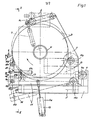
- Fig. 1 eine Ansicht der Vorrichtung in der Arbeitsstellung,
- Fig. 2 einen senkrechten Schnitt gemäß der Schnittlinie II - II in Fig.l mit ausgezogenen Linien, wobei mit strichpunktierten Linien die Tragplatte in der Aufnahmestellung angedeutet ist,
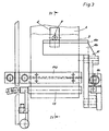
- Fig. 3 eine Stirnansicht des Greifers gemäß der Pfeilrichtung III in Fig.l in vergrößerter Darstellung,
- Fig. 4 einen senkrechten Teilschnitt gemäß der Schnittlinie IV - IV in Fig.3,
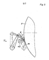
- Fig. 5 eine der Fig.4 entsprechende Darstellung einer alternativen Ausführungsform,
- Fig. 6 eine Teilansicht gemäß dem Pfeil VI in Fig.5,
- Fig. 7 eine Teilansicht gemäß dem Pfeil VII in Fig.6,
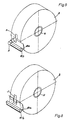
- Fig. 8 eine perspektivische Darstellung einer Bobine mit durch Sauger angehobenen Ecken des Bahnanfanges, wobei jedoch die Sauger der besseren Ubersichtlichkeit wegen weggelassen worden sind, und
- Fig. 9 eine perspektivische Ansicht einer Bobine und eines Sensors beim Abtasten des mittels eines Klebebandes festgelegten Bahnanfanges.
- 1 is a view of the device in the working position,
- 2 is a vertical section along the section line II - II in Fig.l with solid lines, the support plate is indicated in the receiving position with dash-dotted lines,
- 3 is an end view of the gripper according to the direction of arrow III in Fig.l in an enlarged view,
- 4 is a vertical partial section along the section line IV - IV in Figure 3,
- 5 shows an illustration corresponding to FIG. 4 of an alternative embodiment,
- 6 shows a partial view according to arrow VI in FIG. 5,
- 7 shows a partial view according to arrow VII in FIG. 6,
- 8 is a perspective view of a bobbin with corners of the start of the web raised by suction cups, but the suction cups have been omitted for the sake of clarity, and
- Fig. 9 is a perspective view of a bobbin and a sensor when scanning the beginning of the path defined by an adhesive tape.
An einem Grundgestell 1 ist mittels einer Lagerachse 2 eine Tragplatte 3 zwischen einer waagerecht liegenden Aufnahmestellung und einer senkrecht stehenden Arbeitsstellung verschwenkbar. Die Arbeitsstellung der Tragplatte 3 ist in den Figuren 1 und 2 mit ausgezogenen Linien dargestellt. Die waagerecht liegende Aufnahmestellung ist in Fig.2 mit strichpunktierten Linien angedeutet. Die Figuren 1 und 2 zeigen weiterhin einen am Grundgestell 1 angeordneten Druckmittelzylinder 4, dessen Kolbenstange 4a über einen an der Lagerachse 2 befestigten Hebel 4b mit der Tragplatte 3 verbunden ist. In der ausgefahrenen Stellung hält die Kolbenstange 4a die Tragplatte 3 in der in Fig.2 mit ausgezogenen Linien gezeichneten Arbeitsstellung; in der eingefahrenen Stellung der Kolbenstange 4a ist die Tragplatte 3 in die waagerecht liegende Aufnahmestellung verschwenkt, die in Fig.2 strichpunktiert eingezeichnet ist.On a base frame 1, a
An der Tragplatte 3 sind beim Ausführungsbeispiel drei Walzen 5a,5b und 5c drehbar gelagert. Während die Walzen 5a und 5b fest an der Tragplatte 3 angeordnet sind, befindet sich die Walze 5c am verschwenkbaren Ende eines Schwenkarmes 6, der durch einen Druckmittelzylinder 7 betätigbar ist. Durch diesen Druckmittelzylinder 7 kann der Schwenkarm 6 mit der Walze 5c aus einer in Fig.1 strichpunktiert eingezeichneten Aufnahmestellung in eine mit ausgezogenen Linien gezeichnete Arbeitsstellung verschwenkt werden.In the exemplary embodiment, three
Die Walzen 5a, 5b und 5c dienen zur Halterung und Lagerung einer Bobine B, die von oben her auf die in der waagerechten Aufnahmestellung befindliche Tragplatte 3 aufgelegt wird. Hierbei kann die Bobine beispielsweise die in Fig.1 strichpunktiert angedeutete Stellung einnehmen. Durch Betätigen des Druckmittelzylinders 7 wird die Walze 5c an den Umfang der Bobine B angedrückt, die auf diese Weise durch die Kraft des Druckmittelzylinders 7 in die mit ausgezogenen Linien in Fig.1 dargestellte endgültige Lage verschoben wird, in der sie an den Walzen 5a und 5b anliegt. Erst nach dieser Ausrichtung wird die Tragplatte 3 mit Hilfe des Druckmittelzylinders 4 in die senkrecht stehende Arbeitsstellung verschwenkt. Der zum Transport der Bobine B dienende Kern K, auf den die Bahn der Bobine B aufgewickelt ist, ist in Fig.l zu erkennen.The
Um den zur Sicherung beim Transport der Bobine B festgelegten Bahnanfang A (siehe Fig.3) in die zum Öffnen der Bobine B geeignete Lage zu bringen, ist die Walze 5b durch einen Motor 8 antreibbar, der an die Rückseite der Tragplatte 3 angeflanscht ist. Durch den durch Pfeile in Fig.l angedeuteten Antrieb der Walze 5b wird die auf den Walzen 5a und 5b aufliegende Bobine B so lange in Pfeilrichtung gedreht, bis ein Sensor 9 den Bahnanfang A erfaßt. Diese Erfassung kann durch zusätzlich auf dem Umfang der Bobine angebrachte Markierungen erfolgen. Als Markierung kann auch gemäß Fig.3 ein Selbstklebestreifen S dienen, durch den der Bahnanfang A an der darunter befindlichen Lage der Bobine B festgelegt ist.In order to bring the web start A (see FIG. 3), which is fixed for securing the bobbin B, into the position suitable for opening the bobbin B, the
Zum Lösen des Bahnanfanges A dient ein Geifer 10, von dem ein erstes Ausführungsbeispiel in den Figuren 1 bis 4 dargestellt ist. Dieser Greifer 10 umfaßt einen als Schaber 10a ausgebildeten Schenkel zur tangentialen Anlage am Umfang der Bobine B sowie einen beweglichen Schenkel 10b, der durch einen Druckmittelzylinder 10c an den als Schaber 10a ausgebildeten Schenkel andrückbar ist, sobald dieser den Bahnanfang A bzw. den Selbstklebestreifen S erfaßt hat.A
Nach diesem Erfassen wird der Greifer 10 durch eine annähernd tangentiale Bewegung relativ zur Bobine B bewegt, die hierdurch gleichzeitig gedreht wird. Bei dem in den Figuren 1 bis 4 dargestellten Ausführungsbeispiel ist zur Erzielung dieser Bewegung der Greifer 10 schwenkbar am vorderen Ende eines Tragarmes 11 gelagert, der seinerseits auf einem Lagerbolzen lla verschwenkbar am Grundgestell 1 angelenkt ist. Die Verschwenkung des Tragarmes 11 erfolgt durch einen Druckmittelzylinder 12, der an einem Ausleger la des Grundgestells 1 angeordnet ist. Die Fig.l zeigt diesen Tragarm 11 mit ausgezogenen Linien in der Wirkstellung und mit strichpunktierten Linien in einer zurückgezogenen Stellung. Die Darstellung zeigt auch die verschwenkbare Lagerung des Greifers 10 mittels eines Lagerbolzens llb am vorderen Ende des Tragarmes 11. Hierdurch ist es möglich, den Greifer 10 durch die Kraft einer Feder 13 in der Ruhestellung gegen einen Anschlag llc zu ziehen, von dem der Greifer 10 abgehoben wird, wenn er mittels des Druckmittelzylinders 12 gegen den Umfang der Bobine B gedrückt wird, wie dies mit ausgezogenen Linien in Fig.1 dargestellt ist. Diese Ausführung ermöglicht ein sicheres Anlegen des als Schaber 10a ausgebildeten Schenkels des Greifers 10 an den Außenumfang der Bobine B zum Zwecke des Erfassens und Lösens des Bahnanfanges A.After this detection, the
In Fig.4 ist mit strichpunktierten Linien die untere Stellung des mit Hilfe des Tragarmes 11 bewegten Greifers 10 eingezeichnet. Diese Darstellung zeigt auch, daß im Bereich zwischen den beiden Endstellungen des Greifers 10 eine Schneidvorrichtung angeordnet ist, mit deren Hilfe der von der Bobine B abgezogene Bahnanfang A abgeschnitten wird, so daß ein neuer Bahnanfang A1 entsteht.In Figure 4 is the lower position with dash-dotted lines of the
Bei dem in Fig.4 dargestellten Ausführungsbeispiel besteht die Schneidvorrichtung 14 aus einer Schneide 14a, die mit einer Vertiefung in einem Klemmbacken-Paar 14b, 14c zusammenwirkt. Die Klemmbacke 14c ist federnd gegenüber dem Grundteil abgestützt, so daß beim Zusammenpressen des Klemmbackenpaares 14b, 14c (wie dies in Fig.4 mit strichpunktierten Linien dargestellt ist) der Bahnanfang A zwischen den Klemmbacken 14b und 14c festgehalten wird und gleichzeitig die Schneide 14a in die Kerbe der Klemmbacke 14b eintritt. Hierdurch wird der vordere Teil des Bahnanfanges A abgetrennt. Der neu entstandene Bahnanfang A1 wird vom oberen Teil des Klemmbacken-Paares 14b, 14c festgehalten.In the exemplary embodiment shown in FIG. 4, the cutting
Sofern eine größere Länge der Bahn, beispielsweise eine Umfangslänge der Bobine B abgeschnitten werden soll, beispielsweise um Verunreinigungen oder Beschädigungen abzutrennen, kann dies gemäß dem Ausführungsbeispiel nach den Figuren 1 bis 4 durch ein Transportwalzenpaar 15 geschehen, das an gegeneinander verschwenkbaren Hebeln drehbar und antreibbar gelagert ist. Fig.4 zeigt ein derartiges Transportwalzenpaar 15, das nach dem Uberführen des Greifers 10 in die untere Endstellung durch einen Druckmittelzylinder 15a in die Wirkstellung überführbar ist und bei seinem Antrieb den Bahnanfang A in der gewünschten Länge bei gleichzeitiger Drehung der Bobine B abzieht, so daß der durch die Schneide 14a der Schneidvorrichtung 14 erfolgende Trennschnitt an jeder gewünschten Stelle erfolgen kann.If a greater length of the web, for example a circumferential length of the bobbin B, is to be cut off, for example in order to separate off dirt or damage, this can be done according to the exemplary embodiment according to FIGS is. 4 shows such a pair of
Bei der alternativen Ausführungsform des Greifers 10 nach Fig.5 wird der bewegliche Schenkel 10b des Greifers 10 durch eine antreibbare Abzugswalze 10d gebildet, so daß das Transportwalzenpaar 15 gemäß Fig.4 entfallen kann, wenn eine größere Länge des Bahnanfanges A abgeschnitten werden soll. Die Ausführungsform nach Fig.5 zeigt weiterhin in Verbindung mit den Figuren 6 und 7 die Anordnung von Saugern 16 seitlich neben dem mittig festgelegten Bahnanfang A. Durch diese Sauger 16 werden die äußeren Ecken des Bahnanfanges A vor dem Erfassen durch den Greifer 10 abgehoben, wie dies insbesondere die Fig.7 und ohne Darstellung der Sauger 16 die Fig.8 zeigen. Der zum Ansaugen der Ecken des Bahnanfanges A notwendige Unterdruck wird auf geeignete Weise erzeugt. Auch die Sauger 16 können gemäß Fig.5 gesteuert bewegt und lediglich für den erforderlichen Zeitpunkt an die Oberfläche der Bobine B angedrückt werden.In the alternative embodiment of the
In Fig.8 ist zu erkennen, daß bei der Verwendung der Sauger 16 der Schaber 10a des Greifers 10 mit einer mittigen Aussparung für den Selbstklebestreifen S versehen ist. Die Fig.9 zeigt in perspektivischer Darstellung die Wirkung des Sensors 9, der in diesem Fall den Selbstklebestreifen S erfaßt.In FIG. 8 it can be seen that when the
Claims (14)
dadurch gekennzeichnet,
daß an einer Tragplatte (3) mindestens zwei Walzen (5a,5b,5c) drehbar gelagert sind, von denen eine Walze (5b) durch einen Motor (8) angetrieben ist, daß ein den an der Bobine (B) zwecks Transportsicherung festgelegten Bahnanfang (A) erfassender, zangenartiger Greifer (10) vorgesehen ist, der gegen den Umfang der Bobine (B) federnd anstellbar ist und dessen einer Schenkel als Schaber (10a) zum Unterfahren des Bahnanfanges (A) bzw. eines den Bahnanfang (A) festlegenden Klebestreifens (S) ausgebildet ist und dessen anderer Schenkel (10b) zum Erfassen des Bahnanfanges (A) bzw. des Klebestreifens (S) gesteuert gegen den als Schaber (10a) ausgebildeten Schenkel andrückbar ist, und daß der Greifer (10) durch eine annähernd tangentiale Bewegung relativ zur Bobine (B) beweglich gelagert ist und den erfaßten Bahnanfang (A) bei gleichzeitiger Drehung der Bobine (B) auf den Walzen (5a,5b) einer Schneidvorrichtung (14) zuführt, deren Schneide (14a) den erfaßten Bahnanfang (A) abtrennt und die den hierdurch entstandenen neuen Bahnanfang (A1) bis zur Übernahme durch eine Transporteinrichtung festhält.1. Device for detecting and releasing the beginning of a web of paper, textile, plastic and / or metal foil wound on a core into a bobbin for further processing on a downstream machine, preferably a packaging machine,
characterized,
that at least two rollers (5a, 5b, 5c) are rotatably mounted on a support plate (3), of which one roller (5b) is driven by a motor (8), that a web start fixed on the reel (B) for the purpose of securing the transport (A) capturing, pliers-like gripper (10) is provided, which can be adjusted resiliently against the circumference of the bobbin (B) and of which one leg as a scraper (10a) for passing under the web start (A) or one defining the web start (A) Adhesive strip (S) is formed and the other leg (10b) for grasping the beginning of the path (A) or the adhesive strip (S) can be pressed in a controlled manner against the leg designed as a scraper (10a), and that the gripper (10) can be approximated by one tangential movement relative to the bobbin (B) is movably mounted and feeds the detected web start (A) while rotating the bobbin (B) on the rollers (5a, 5b) to a cutting device (14), the cutting edge (14a) of which records the web start ( A) separates and the this creates the new start of the path (A1) until it is taken over by a transport device.
Priority Applications (1)
| Application Number | Priority Date | Filing Date | Title |
|---|---|---|---|
| AT85116342T ATE47578T1 (en) | 1985-01-29 | 1985-12-20 | DEVICE FOR GRASPING AND RELEASING THE BEGINNING OF A BOBINE. |
Applications Claiming Priority (2)
| Application Number | Priority Date | Filing Date | Title |
|---|---|---|---|
| DE3502808 | 1985-01-29 | ||
| DE19853502808 DE3502808A1 (en) | 1985-01-29 | 1985-01-29 | DEVICE FOR DETECTING AND DETACHING THE BEGINNING OF A BOBINE |
Publications (3)
| Publication Number | Publication Date |
|---|---|
| EP0189582A2 true EP0189582A2 (en) | 1986-08-06 |
| EP0189582A3 EP0189582A3 (en) | 1988-02-03 |
| EP0189582B1 EP0189582B1 (en) | 1989-10-25 |
Family
ID=6260994
Family Applications (1)
| Application Number | Title | Priority Date | Filing Date |
|---|---|---|---|
| EP85116342A Expired EP0189582B1 (en) | 1985-01-29 | 1985-12-20 | Device for grasping and detaching the leading end of a wound roll |
Country Status (4)
| Country | Link |
|---|---|
| US (1) | US4688736A (en) |
| EP (1) | EP0189582B1 (en) |
| AT (1) | ATE47578T1 (en) |
| DE (2) | DE3502808A1 (en) |
Cited By (8)
| Publication number | Priority date | Publication date | Assignee | Title |
|---|---|---|---|---|
| EP0227951A2 (en) * | 1985-11-28 | 1987-07-08 | Sanjo Machine Works Ltd. | Apparatus for continuously supplying sheets from supply rolls |
| EP0331634A1 (en) * | 1988-02-25 | 1989-09-06 | Fabriques De Tabac Reunies S.A. | Procedure and device for opening a paper web bobbin |
| WO1995029116A1 (en) * | 1994-04-26 | 1995-11-02 | Massey University | Improvements relating to application of adhesive tape |
| EP0692444A1 (en) * | 1994-07-14 | 1996-01-17 | KOENIG & BAUER-ALBERT AKTIENGESELLSCHAFT | Material for attaching the leading end of a roll of paper web |
| DE10219179A1 (en) * | 2002-04-29 | 2003-11-13 | Koenig & Bauer Ag | Device for preparing a roll of material |
| DE10343452A1 (en) * | 2003-09-19 | 2005-04-14 | Voith Paper Patent Gmbh | Cutter unit removing strip from winding of e.g. fibrous paper web, includes frame with suction unit and spaced blades removing layer from wounddrum |
| DE10343451A1 (en) * | 2003-09-19 | 2005-04-14 | Voith Paper Patent Gmbh | Assembly removes sample section of paper from a roll for feed between clamping track with cutter assembly |
| WO2018172400A1 (en) * | 2017-03-22 | 2018-09-27 | Philip Morris Products S.A. | Method to remove an adhesive label from a bobbin and apparatus to detach an adhesive label from an end portion of a coiled sheet in a bobbin |
Families Citing this family (12)
| Publication number | Priority date | Publication date | Assignee | Title |
|---|---|---|---|---|
| US4911374A (en) * | 1986-01-21 | 1990-03-27 | Philip Morris Incorporated | System and method for use in delaminating bobbins of paper material |
| US4821972A (en) * | 1986-01-21 | 1989-04-18 | Philip Morris Incorporated | System and method for use in handling and delaminating bobbins of paper material |
| IT1238288B (en) * | 1990-03-27 | 1993-07-12 | Gd Spa | DEVICE FOR THE REMOVAL OF A CLOSING ADHESIVE CLAMP FROM A BAND OF TAPE MATERIAL. |
| IT1245766B (en) * | 1991-02-26 | 1994-10-14 | Gd Spa | METHOD AND DEVICE FOR CUTTING AN ADHESIVE CLAMP FOR CLOSING A BAND OF TAPE MATERIAL. |
| IT1257624B (en) * | 1992-01-09 | 1996-02-01 | Gd Spa | DEVICE FOR THE COLLECTION OF THE HEAD OF THE TAPE OF A NEW REEL AND ITS TRANSFER TO A SUBSEQUENT OPERATING STATION |
| DE4212095C1 (en) * | 1992-04-10 | 1993-08-19 | Man Roland Druckmaschinen Ag, 6050 Offenbach, De | |
| JP3127655B2 (en) * | 1993-03-22 | 2001-01-29 | ソニー株式会社 | Modulator and demodulator |
| DE10343423A1 (en) * | 2003-09-19 | 2005-04-14 | Voith Paper Patent Gmbh | Device which is especially reel-spool storage station has winding reel producing rotational movement for rolling off of material roll, and winding reel and cutting device are movable in relation to one another in traversing direction |
| DE10343446A1 (en) * | 2003-09-19 | 2005-04-14 | Voith Paper Patent Gmbh | Sampler removing one or more strips from wound drum of fibrous web in papermaking plant, is fitted under base flap beneath drum and pivots up for strip sampling |
| DE10343420A1 (en) * | 2003-09-19 | 2005-04-14 | Voith Paper Patent Gmbh | Device which is especially reel-spool storage station has winding reel producing rotational movement for rolling off of material roll, and winding reel and cutting device are movable in relation to one another in traversing direction |
| DE10343454A1 (en) * | 2003-09-19 | 2005-04-14 | Voith Paper Patent Gmbh | Winding drum for papermaking web, with unit sampling outer winding, is arranged for relative movement between sampling unit and drum |
| DE102022128890A1 (en) | 2022-11-01 | 2024-05-02 | Körber Technologies Gmbh | Arrangement for automatically loading a connecting unit with bobbins |
Citations (6)
| Publication number | Priority date | Publication date | Assignee | Title |
|---|---|---|---|---|
| US1425076A (en) * | 1920-12-29 | 1922-08-08 | Dwight Fisk J | Reel |
| US2880778A (en) * | 1956-09-13 | 1959-04-07 | United States Steel Corp | Apparatus for pulling the end from a coil of strip |
| US3010672A (en) * | 1959-09-01 | 1961-11-28 | Jr Owen S Cecil | Coil opener and uncoiler |
| DE2145179A1 (en) * | 1970-09-09 | 1972-03-16 | Komatsu Mfg Co Ltd | Method for the automatic loading of a rolled up material |
| DE2361300A1 (en) * | 1973-12-08 | 1975-06-12 | Agfa Gevaert Ag | Gluing machine cutter mechanism - has steel strip upper knife working between lower ones in gluing table |
| EP0048125A1 (en) * | 1980-09-12 | 1982-03-24 | DAVY McKEE (POOLE) LIMITED | Apparatus for detecting the position of the end of the outer turn of a coil of strip material |
Family Cites Families (2)
| Publication number | Priority date | Publication date | Assignee | Title |
|---|---|---|---|---|
| GB948723A (en) * | 1961-10-12 | 1964-02-05 | Beteiligungs & Patentverw Gmbh | Unwinding device for reels of strip material |
| GB1247296A (en) * | 1968-09-13 | 1971-09-22 | Hitachi Ltd | A method of and an apparatus for detecting the position of the end of a coil of strip material |
-
1985
- 1985-01-29 DE DE19853502808 patent/DE3502808A1/en not_active Withdrawn
- 1985-12-20 EP EP85116342A patent/EP0189582B1/en not_active Expired
- 1985-12-20 AT AT85116342T patent/ATE47578T1/en not_active IP Right Cessation
- 1985-12-20 DE DE8585116342T patent/DE3573914D1/en not_active Expired
-
1986
- 1986-01-10 US US06/818,532 patent/US4688736A/en not_active Expired - Fee Related
Patent Citations (6)
| Publication number | Priority date | Publication date | Assignee | Title |
|---|---|---|---|---|
| US1425076A (en) * | 1920-12-29 | 1922-08-08 | Dwight Fisk J | Reel |
| US2880778A (en) * | 1956-09-13 | 1959-04-07 | United States Steel Corp | Apparatus for pulling the end from a coil of strip |
| US3010672A (en) * | 1959-09-01 | 1961-11-28 | Jr Owen S Cecil | Coil opener and uncoiler |
| DE2145179A1 (en) * | 1970-09-09 | 1972-03-16 | Komatsu Mfg Co Ltd | Method for the automatic loading of a rolled up material |
| DE2361300A1 (en) * | 1973-12-08 | 1975-06-12 | Agfa Gevaert Ag | Gluing machine cutter mechanism - has steel strip upper knife working between lower ones in gluing table |
| EP0048125A1 (en) * | 1980-09-12 | 1982-03-24 | DAVY McKEE (POOLE) LIMITED | Apparatus for detecting the position of the end of the outer turn of a coil of strip material |
Cited By (13)
| Publication number | Priority date | Publication date | Assignee | Title |
|---|---|---|---|---|
| EP0227951A2 (en) * | 1985-11-28 | 1987-07-08 | Sanjo Machine Works Ltd. | Apparatus for continuously supplying sheets from supply rolls |
| EP0227951A3 (en) * | 1985-11-28 | 1988-08-03 | Sanjo Machine Works Ltd. | Apparatus for continuously supplying sheets from supply rolls |
| EP0331634A1 (en) * | 1988-02-25 | 1989-09-06 | Fabriques De Tabac Reunies S.A. | Procedure and device for opening a paper web bobbin |
| US4995406A (en) * | 1988-02-25 | 1991-02-26 | Fabriques De Tabac Reunies, S.A. | Apparatus and method for opening a reel of paper stripping |
| WO1995029116A1 (en) * | 1994-04-26 | 1995-11-02 | Massey University | Improvements relating to application of adhesive tape |
| EP0692444A1 (en) * | 1994-07-14 | 1996-01-17 | KOENIG & BAUER-ALBERT AKTIENGESELLSCHAFT | Material for attaching the leading end of a roll of paper web |
| DE10219179A1 (en) * | 2002-04-29 | 2003-11-13 | Koenig & Bauer Ag | Device for preparing a roll of material |
| DE10219179B4 (en) * | 2002-04-29 | 2005-04-28 | Koenig & Bauer Ag | Device for preparing a roll of material |
| DE10343452A1 (en) * | 2003-09-19 | 2005-04-14 | Voith Paper Patent Gmbh | Cutter unit removing strip from winding of e.g. fibrous paper web, includes frame with suction unit and spaced blades removing layer from wounddrum |
| DE10343451A1 (en) * | 2003-09-19 | 2005-04-14 | Voith Paper Patent Gmbh | Assembly removes sample section of paper from a roll for feed between clamping track with cutter assembly |
| WO2018172400A1 (en) * | 2017-03-22 | 2018-09-27 | Philip Morris Products S.A. | Method to remove an adhesive label from a bobbin and apparatus to detach an adhesive label from an end portion of a coiled sheet in a bobbin |
| RU2753967C2 (en) * | 2017-03-22 | 2021-08-24 | Филип Моррис Продактс С.А. | Method for removing adhesive label from roll and device for separating adhesive label from the end part of wound sheet in roll |
| US11267669B2 (en) | 2017-03-22 | 2022-03-08 | Philip Morris Products S.A. | Method to remove an adhesive label from a bobbin and apparatus to detach an adhesive label from an end portion of a coiled sheet in a bobbin |
Also Published As
| Publication number | Publication date |
|---|---|
| EP0189582B1 (en) | 1989-10-25 |
| EP0189582A3 (en) | 1988-02-03 |
| ATE47578T1 (en) | 1989-11-15 |
| US4688736A (en) | 1987-08-25 |
| DE3573914D1 (en) | 1989-11-30 |
| DE3502808A1 (en) | 1986-07-31 |
Similar Documents
| Publication | Publication Date | Title |
|---|---|---|
| EP0189582B1 (en) | Device for grasping and detaching the leading end of a wound roll | |
| EP0442038B1 (en) | Method and device for automatically replacing a full roll by a new winding core | |
| EP0638499B1 (en) | Method and device for joining webs of material, in particular packaging material | |
| EP0940360B1 (en) | Method and device for splicing webs | |
| EP0016691A1 (en) | Apparatus for automatically filling sacks at the outlet nozzle of a filling funnel | |
| DE3918552C2 (en) | Machine for preparing paper rolls for the splicing process | |
| DE69914444T2 (en) | Device for forming a splice connection in a paper web | |
| DE2223557C2 (en) | Process for applying stickers to a continuous web | |
| DE3441205A1 (en) | Reel (bobbin) changing device | |
| EP0300220A2 (en) | Winding method for winding material fed without interruption on the several winding cores, as well as two-drum winder | |
| DE4436719A1 (en) | Splicer for packaging material webs wound in a bobbin-like manner | |
| EP0379861B1 (en) | Device for joining sheets together | |
| WO2021090082A1 (en) | Device and method for winding a thread | |
| EP0453711A1 (en) | Procedure for withdrawing and depositing of punched out piles of sheets or similar piles of lamellar material from an entire pile and device for this | |
| DE3531731C1 (en) | Device for continuously feeding a band-shaped material to a processing machine | |
| EP0395893B1 (en) | Device for winding or rewinding a web of paper | |
| CH617409A5 (en) | System for jogging material sheets to form a stack | |
| DE102008051581B4 (en) | Device for removing a printing plate from the plate cylinder of a printing press | |
| EP0193626A1 (en) | Device for applying a tape or the like to corrugated boards, paper webs or the like | |
| DE4413885A1 (en) | Method of spooling continuous thread | |
| EP1529011A2 (en) | Method, system, and device for preparing a winding reel used for changing reels in a flying manner, detecting a web of material, and applying a double-sided adhesive tape to a surface | |
| DE2453525C2 (en) | Device for the formation of thread clamp blanks and their correct positioning with continuously conveyed folded sheets | |
| DE10112636A1 (en) | Method for applying adhesive to end of roll of material comprises winding it so that its inner surface is upwards, adhesive then being applied and strip rewound so that it sticks to surface of roll | |
| DE4203934C2 (en) | Device for detaching the tail thread from the surface of cops | |
| DE4211984A1 (en) | DEVICE FOR PROCESSING A THREAD RESERVE |
Legal Events
| Date | Code | Title | Description |
|---|---|---|---|
| PUAI | Public reference made under article 153(3) epc to a published international application that has entered the european phase |
Free format text: ORIGINAL CODE: 0009012 |
|
| AK | Designated contracting states |
Kind code of ref document: A2 Designated state(s): AT BE CH DE FR GB IT LI LU NL SE |
|
| PUAL | Search report despatched |
Free format text: ORIGINAL CODE: 0009013 |
|
| AK | Designated contracting states |
Kind code of ref document: A3 Designated state(s): AT BE CH DE FR GB IT LI LU NL SE |
|
| RAP1 | Party data changed (applicant data changed or rights of an application transferred) |
Owner name: NIEPMANN TRAYLIFT TRANSPORTSYSTEME GMBH & CO. KG |
|
| 17P | Request for examination filed |
Effective date: 19880628 |
|
| 17Q | First examination report despatched |
Effective date: 19881017 |
|
| GRAA | (expected) grant |
Free format text: ORIGINAL CODE: 0009210 |
|
| ITF | It: translation for a ep patent filed |
Owner name: ING. ZINI MARANESI & C. S.R.L. |
|
| AK | Designated contracting states |
Kind code of ref document: B1 Designated state(s): AT BE CH DE FR GB IT LI LU NL SE |
|
| PG25 | Lapsed in a contracting state [announced via postgrant information from national office to epo] |
Ref country code: SE Effective date: 19891025 Ref country code: NL Effective date: 19891025 Ref country code: BE Effective date: 19891025 |
|
| REF | Corresponds to: |
Ref document number: 47578 Country of ref document: AT Date of ref document: 19891115 Kind code of ref document: T |
|
| ET | Fr: translation filed | ||
| GBT | Gb: translation of ep patent filed (gb section 77(6)(a)/1977) | ||
| REF | Corresponds to: |
Ref document number: 3573914 Country of ref document: DE Date of ref document: 19891130 |
|
| PG25 | Lapsed in a contracting state [announced via postgrant information from national office to epo] |
Ref country code: AT Effective date: 19891220 |
|
| PG25 | Lapsed in a contracting state [announced via postgrant information from national office to epo] |
Ref country code: LU Free format text: LAPSE BECAUSE OF NON-PAYMENT OF DUE FEES Effective date: 19891231 Ref country code: LI Effective date: 19891231 Ref country code: CH Effective date: 19891231 |
|
| NLV1 | Nl: lapsed or annulled due to failure to fulfill the requirements of art. 29p and 29m of the patents act | ||
| PLBE | No opposition filed within time limit |
Free format text: ORIGINAL CODE: 0009261 |
|
| STAA | Information on the status of an ep patent application or granted ep patent |
Free format text: STATUS: NO OPPOSITION FILED WITHIN TIME LIMIT |
|
| REG | Reference to a national code |
Ref country code: CH Ref legal event code: PL |
|
| 26N | No opposition filed | ||
| ITTA | It: last paid annual fee | ||
| REG | Reference to a national code |
Ref country code: GB Ref legal event code: 732E |
|
| REG | Reference to a national code |
Ref country code: FR Ref legal event code: TP |
|
| PGFP | Annual fee paid to national office [announced via postgrant information from national office to epo] |
Ref country code: GB Payment date: 19971103 Year of fee payment: 13 |
|
| PGFP | Annual fee paid to national office [announced via postgrant information from national office to epo] |
Ref country code: FR Payment date: 19971117 Year of fee payment: 13 |
|
| PGFP | Annual fee paid to national office [announced via postgrant information from national office to epo] |
Ref country code: DE Payment date: 19980218 Year of fee payment: 13 |
|
| PG25 | Lapsed in a contracting state [announced via postgrant information from national office to epo] |
Ref country code: GB Free format text: LAPSE BECAUSE OF NON-PAYMENT OF DUE FEES Effective date: 19981220 |
|
| GBPC | Gb: european patent ceased through non-payment of renewal fee |
Effective date: 19981220 |
|
| PG25 | Lapsed in a contracting state [announced via postgrant information from national office to epo] |
Ref country code: FR Free format text: LAPSE BECAUSE OF NON-PAYMENT OF DUE FEES Effective date: 19990831 |
|
| REG | Reference to a national code |
Ref country code: FR Ref legal event code: ST |
|
| PG25 | Lapsed in a contracting state [announced via postgrant information from national office to epo] |
Ref country code: DE Free format text: LAPSE BECAUSE OF NON-PAYMENT OF DUE FEES Effective date: 19991001 |