EP0189170A2 - Einhebelzapfventil - Google Patents
Einhebelzapfventil Download PDFInfo
- Publication number
- EP0189170A2 EP0189170A2 EP86100742A EP86100742A EP0189170A2 EP 0189170 A2 EP0189170 A2 EP 0189170A2 EP 86100742 A EP86100742 A EP 86100742A EP 86100742 A EP86100742 A EP 86100742A EP 0189170 A2 EP0189170 A2 EP 0189170A2
- Authority
- EP
- European Patent Office
- Prior art keywords
- lever
- stop
- shoulder
- trigger
- tap according
- Prior art date
- Legal status (The legal status is an assumption and is not a legal conclusion. Google has not performed a legal analysis and makes no representation as to the accuracy of the status listed.)
- Granted
Links
Images


Classifications
-
- F—MECHANICAL ENGINEERING; LIGHTING; HEATING; WEAPONS; BLASTING
- F16—ENGINEERING ELEMENTS AND UNITS; GENERAL MEASURES FOR PRODUCING AND MAINTAINING EFFECTIVE FUNCTIONING OF MACHINES OR INSTALLATIONS; THERMAL INSULATION IN GENERAL
- F16K—VALVES; TAPS; COCKS; ACTUATING-FLOATS; DEVICES FOR VENTING OR AERATING
- F16K31/00—Actuating devices; Operating means; Releasing devices
- F16K31/44—Mechanical actuating means
- F16K31/60—Handles
- F16K31/605—Handles for single handle mixing valves
-
- F—MECHANICAL ENGINEERING; LIGHTING; HEATING; WEAPONS; BLASTING
- F16—ENGINEERING ELEMENTS AND UNITS; GENERAL MEASURES FOR PRODUCING AND MAINTAINING EFFECTIVE FUNCTIONING OF MACHINES OR INSTALLATIONS; THERMAL INSULATION IN GENERAL
- F16K—VALVES; TAPS; COCKS; ACTUATING-FLOATS; DEVICES FOR VENTING OR AERATING
- F16K11/00—Multiple-way valves, e.g. mixing valves; Pipe fittings incorporating such valves
- F16K11/02—Multiple-way valves, e.g. mixing valves; Pipe fittings incorporating such valves with all movable sealing faces moving as one unit
- F16K11/06—Multiple-way valves, e.g. mixing valves; Pipe fittings incorporating such valves with all movable sealing faces moving as one unit comprising only sliding valves, i.e. sliding closure elements
- F16K11/078—Multiple-way valves, e.g. mixing valves; Pipe fittings incorporating such valves with all movable sealing faces moving as one unit comprising only sliding valves, i.e. sliding closure elements with pivoted and linearly movable closure members
- F16K11/0782—Single-lever operated mixing valves with closure members having flat sealing faces
Definitions
- the present invention relates to a single-grip lever water tap in which the amount and temperature of mixed water are adjusted by raising and lowering the lever, the temperature being adjusted by turning the lever, and the movable lever and the stationary body have stop means working in conjunction with each other to limit the preselected extreme position of the turning movement of the lever, and to a single-grip lever tap in which the amount and temperature of mixed water are adjusted by raising and lowering the lever, the temperature being adjusted by turning the lever, and the movable lever and the stationary body have stop means working in conjunction with each other to limit the preselected extreme position of the turning movement of the lever, the lever being additionally equipped with user-controlled release means by the moving of which the said extreme position limit can be overridden.
- a single-grip lever tap of this type is previously known from, for example, DE patent 34 02 103. It has a springloaded pressbutton attached with bearings to the control lever, and, attached to the pressbutton, a pin working in conjunction with the stop in the body of the tap, in which case the limiting pin can pass beyond the said stop when the pressbutton is pressed.
- this structure has a disadvantage in its complicated structure and partial weakness of material, which is, among other things, dependent on the strength of the pin.
- such a pin structure is cumbersome if it is desired that it will function smoothly in the different turning and lifting positions of the lever.
- the object of the present invention is therefore to provide a single-grip lever tap having a possibility of limiting the temperature and having a button enabling this stop to be overridden, but in such a way that the structure of the tap is not immoderately complicated and that the limiting mechanism is at the same time both reliable in operation and has a long useful life.
- the lever tap according to the invention is characterized in that the stop means in the body is a shoulder formed in the cup-like part below the central part of the lever and parallel to the side line of the cup, and that the stop in the lever is a stop part oriented towards the said shoulder and normally engaging it, the stop part being raisable over the shoulder.
- the release means consists of a trigger attached so that it can turn inside the central part, one of its ends serving as the stop part in the lever and the other end being capable of being affected from outside the lever.
- One end of the trigger can be shaped into a pressbutton which protrudes from an opening at the root of the lever.
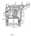
- Figure 1 thus shows a cross section of the upper part of a conventional single-grip lever tap.
- the lower part which in a manner known to an expert in the art includes the water-mixing part with its ceramic plates, is not shown here.
- the movable lever of the tap comprises a protrusion, i.e. the actual lever 1, which is cut in the figure, the upper part la, the interior part lb, and the skirting part lc around the interior part, all of these parts making up one unit.
- This lever is attached by means of a screw to a spindle 2, which in a known manner moves the movable upper ceramic plate.
- the amount of mixed water is adjusted by raising and lowering the lever 1, and the temperature of mixed water is adjusted by turning the lever to the right or to the left.
- the protective cup 4 fastened to the upper part of the body of the tap is designed so as to have a spherical exterior surface, and furthermore, a shoulder, or stop 14, parallel to the side line of the cup, has been made in this exterior surface.
- the end 9 of the trigger oriented obliquely downwards, engages this stop, the trigger being turnably attached to the interior part lb of the lever, the opposite end of the trigger forming a pressbutton 6.
- part 9 of the trigger comes against the stop 14, thereby limiting the movement of the lever.
- the pressbutton 6 is pressed downwards, the part 9 rises over the stop 14, whereupon the lever 1 can be turned further to the left, all the way to the extreme position.
- Figure 2 depicts a top view of the tap.
- the fastening screw of the lever 1 is covered by a covering plate 7, and the pressbutton 6 protrudes from the opening next to the covering plate 7.
- FIG. 3 shows a top view of the trigger, which is in general indicated by numeral 8.
- the trigger is preferably made from a resilient strong plastic material.
- the end opposite in relation to the pressbutton 6 is preferably branched in such a way that the thinner, resilient tongue 10 at the same time forms a spring which keeps the part 9 in contact with the exterior surface of the protective cup 4.
- the trigger has in the middle a groove 11 having the shape of a partial cylinder, the groove leaning against a correspondingly designed area in part lb, thereby forming the turning axis of the trigger.
- the trigger is provided with a hole 12 through which the lever can be fastened to the spindle 2.
- the shape of the protective cup 4 is better seen in Figures 4 and 5.
- the outer surface 13 of the protective cup is mainly spherical in such a way that the center point of the spherical surface is the same as the center point of the movement of the lever 1. In this manner the part 9 of the trigger remains steadily against the surface 13 of the protective cup 4, regardless of the movements of the lever 1.
- the stop, or shoulder 14, protrudes from this spherical surface, as is best seen in Figure 4.
- the limiting position determined by the stop 14 can, furthermore, be selected by positioning the protective cup 4 in the desired manner in relation to the body of the tap.
- the protective cup is provided with inside ring-like toothing 15, which can engage a correspondingly shaped sleeve-like part 5 fastened to the body, the part 5 being shown in Figure 1. Shifting the position of the protective cup 4 requires, of course, that the cover 7 of the lever tap be removed and the lever 1 be detached from the spindle 2, whereafter the protective cup 4 can be raised and positioned at a new angle.
- Figures 6 and 7 depict a slightly different embodiment of the protective cup.
- the protective cup is in other respects similar to that in Figures 4 and 5, but at the top the shoulder 14 is cut in such a way that a second shoulder 14a, extending towards the periphery, is formed.
- the purpose of this shoulder is to prevent the tap from being opened from the closed position when the lever 1 has been turned beyond the limit position determined by the stop 14.
- the part 9 of the lever 8 is so long that, when the tap is in the closed position, the lower end of the part 9 remains just above the shoulder 14a.
- the trigger can be moved over the stop 14 when the tap is open, but a tap which has been turned to a position giving too hot water cannot be opened without first turning it to the "permitted range.”
- Figure 8 depicts an embodiment slightly different from that in Figure 1.
- the structure is the same as in Figure 1 , but the end 17 of the trigger remains inside the upper part of the lever and is affected by means of a separate pressbutton 16 in the center, the pressbutton being loaded by a helical spring 18 leaning against the central part lb. It is clear that even in this case the resilience could be in the trigger itself.
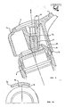
- Figures 9 and 10 depict one alternative embodiment, which has no trigger but in which the lever 1 itself can be lifted in order to release the limiting action.
- the inner surface of the skirting part lc of the lever 1 is provided with a shoulder 19, which hits the shoulder 14 in the protective cup 4.
- the shoulder 19, as seen from above remains on the right-hand side of the shoulder 14, as seen in Figure 10.
- the limit position can be overridden by raising the entire lever 1 upwards, the spring 21 compressing between the head of the fastening screw 20 and the central part lb.
Landscapes
- Engineering & Computer Science (AREA)
- General Engineering & Computer Science (AREA)
- Mechanical Engineering (AREA)
- Domestic Plumbing Installations (AREA)
- Mechanically-Actuated Valves (AREA)
- Decoration Of Textiles (AREA)
- Heat Sensitive Colour Forming Recording (AREA)
- Control Of Turbines (AREA)
- Curing Cements, Concrete, And Artificial Stone (AREA)
- Inorganic Insulating Materials (AREA)
- Secondary Cells (AREA)
- Multiple-Way Valves (AREA)
Priority Applications (1)
| Application Number | Priority Date | Filing Date | Title |
|---|---|---|---|
| AT86100742T ATE47212T1 (de) | 1985-01-24 | 1986-01-21 | Einhebelzapfventil. |
Applications Claiming Priority (2)
| Application Number | Priority Date | Filing Date | Title |
|---|---|---|---|
| FI850315 | 1985-01-24 | ||
| FI850315A FI70994C (fi) | 1985-01-24 | 1985-01-24 | Engreppskran |
Publications (3)
| Publication Number | Publication Date |
|---|---|
| EP0189170A2 true EP0189170A2 (de) | 1986-07-30 |
| EP0189170A3 EP0189170A3 (en) | 1987-08-19 |
| EP0189170B1 EP0189170B1 (de) | 1989-10-11 |
Family
ID=8520255
Family Applications (1)
| Application Number | Title | Priority Date | Filing Date |
|---|---|---|---|
| EP86100742A Expired EP0189170B1 (de) | 1985-01-24 | 1986-01-21 | Einhebelzapfventil |
Country Status (6)
| Country | Link |
|---|---|
| EP (1) | EP0189170B1 (de) |
| AT (1) | ATE47212T1 (de) |
| DE (1) | DE3666284D1 (de) |
| DK (1) | DK161905C (de) |
| FI (1) | FI70994C (de) |
| NO (1) | NO158695C (de) |
Cited By (8)
| Publication number | Priority date | Publication date | Assignee | Title |
|---|---|---|---|---|
| DE3621713A1 (de) * | 1986-06-28 | 1988-01-07 | Grohe Kg Hans | Betaetigungseinrichtung fuer ein sanitaeres einhebel-mischventil |
| FR2611851A1 (fr) * | 1985-09-25 | 1988-09-09 | Vaergaarda Armaturfab Ab | Dispositif de robinetterie melangeuse pour liquides |
| GB2211585A (en) * | 1987-10-27 | 1989-07-05 | Dorf Ind Pty Ltd | Single handle mixing tap or valve |
| EP0426639A1 (de) * | 1989-10-31 | 1991-05-08 | Staar Societe Anonyme | Einhebelmischventil |
| EP0643246A1 (de) * | 1993-09-14 | 1995-03-15 | Oras Oy | Einhebel-Mischarmatur mit Temperatur und Durchflussbegrenzer |
| US5462224A (en) * | 1990-10-05 | 1995-10-31 | Toto Ltd. | Hot and cold water mixing discharge device |
| EP0819877A3 (de) * | 1996-07-18 | 1998-08-05 | Friedrich Grohe Aktiengesellschaft | Betätigungseinrichtung für ein Einhebelmischventil |
| GB2351548A (en) * | 1999-06-29 | 2001-01-03 | Aqualisa Products Ltd | Rotary control knob with an overridable stop |
Families Citing this family (1)
| Publication number | Priority date | Publication date | Assignee | Title |
|---|---|---|---|---|
| DE19923899C2 (de) * | 1999-05-25 | 2003-11-27 | Hans-Georg Boehm | Zweistufen Einhandmisch-Wasserhahn |
Family Cites Families (4)
| Publication number | Priority date | Publication date | Assignee | Title |
|---|---|---|---|---|
| DE1920254U (de) * | 1965-05-18 | 1965-07-22 | Hansa Metallwerke Ag | Mischventil. |
| DE2101580A1 (de) * | 1971-01-14 | 1972-07-27 | Fa. Otto Egelhof, 7012 Fellbach | Betätigungsvorrichtung für Hähne, insbesondere für Gashähne mit zwei Arbeitsdrehstellungen |
| US4456219A (en) * | 1983-08-29 | 1984-06-26 | American Standard Inc. | Spring-locking handle mechanism |
| DE3402103C1 (de) * | 1984-01-21 | 1985-03-28 | Heinrich Schulte & Sohn Gmbh & Co Kg, 5860 Iserlohn | Einhebel-Mischbatterie |
-
1985
- 1985-01-24 FI FI850315A patent/FI70994C/fi not_active IP Right Cessation
-
1986
- 1986-01-21 AT AT86100742T patent/ATE47212T1/de not_active IP Right Cessation
- 1986-01-21 DE DE8686100742T patent/DE3666284D1/de not_active Expired
- 1986-01-21 EP EP86100742A patent/EP0189170B1/de not_active Expired
- 1986-01-23 NO NO860238A patent/NO158695C/no unknown
- 1986-01-23 DK DK034586A patent/DK161905C/da not_active IP Right Cessation
Cited By (12)
| Publication number | Priority date | Publication date | Assignee | Title |
|---|---|---|---|---|
| FR2611851A1 (fr) * | 1985-09-25 | 1988-09-09 | Vaergaarda Armaturfab Ab | Dispositif de robinetterie melangeuse pour liquides |
| AU592368B2 (en) * | 1985-09-25 | 1990-01-11 | Vargarda Armatur A.B. | A mixing valve device |
| DE3621713A1 (de) * | 1986-06-28 | 1988-01-07 | Grohe Kg Hans | Betaetigungseinrichtung fuer ein sanitaeres einhebel-mischventil |
| GB2211585A (en) * | 1987-10-27 | 1989-07-05 | Dorf Ind Pty Ltd | Single handle mixing tap or valve |
| EP0426639A1 (de) * | 1989-10-31 | 1991-05-08 | Staar Societe Anonyme | Einhebelmischventil |
| BE1003580A3 (fr) * | 1989-10-31 | 1992-04-28 | Staar Sa | Dispositif de reglage de debit pour robinet. |
| US5462224A (en) * | 1990-10-05 | 1995-10-31 | Toto Ltd. | Hot and cold water mixing discharge device |
| US5551630A (en) * | 1990-10-05 | 1996-09-03 | Toto Ltd. | Hot and cold water mixing discharge device |
| EP0643246A1 (de) * | 1993-09-14 | 1995-03-15 | Oras Oy | Einhebel-Mischarmatur mit Temperatur und Durchflussbegrenzer |
| EP0819877A3 (de) * | 1996-07-18 | 1998-08-05 | Friedrich Grohe Aktiengesellschaft | Betätigungseinrichtung für ein Einhebelmischventil |
| US5992457A (en) * | 1996-07-18 | 1999-11-30 | Friedrich Grohe Ag | Single-lever mixing valve with override |
| GB2351548A (en) * | 1999-06-29 | 2001-01-03 | Aqualisa Products Ltd | Rotary control knob with an overridable stop |
Also Published As
| Publication number | Publication date |
|---|---|
| FI70994C (fi) | 1986-10-27 |
| EP0189170B1 (de) | 1989-10-11 |
| EP0189170A3 (en) | 1987-08-19 |
| FI850315A0 (fi) | 1985-01-24 |
| NO158695B (no) | 1988-07-11 |
| DK161905B (da) | 1991-08-26 |
| FI70994B (fi) | 1986-07-18 |
| DK34586A (da) | 1986-07-25 |
| ATE47212T1 (de) | 1989-10-15 |
| DK34586D0 (da) | 1986-01-23 |
| DK161905C (da) | 1992-02-03 |
| DE3666284D1 (en) | 1989-11-16 |
| NO158695C (no) | 1988-10-19 |
| NO860238L (no) | 1986-07-25 |
Similar Documents
| Publication | Publication Date | Title |
|---|---|---|
| EP0189170A2 (de) | Einhebelzapfventil | |
| EP0972478B1 (de) | Dampfauslass für Kochgeräte | |
| US4237629A (en) | Apparatus for actuating the operation of a snowplow | |
| US6336245B1 (en) | Door stopper | |
| US5425161A (en) | Rotary closure for a sports shoe | |
| RU2533700C2 (ru) | Крышка для кастрюли-скороварки | |
| JPS6412921A (en) | Control device for automatic transmission | |
| US6105808A (en) | Opening and closing safety device for a pressure cooker | |
| JPS624125B2 (de) | ||
| US7762420B2 (en) | Pressure cooker | |
| EP0296281A1 (de) | Feuerzeug | |
| CA1285840C (en) | Tilt mechanism for infant incubator | |
| DE69703627T2 (de) | Brühgetränkevorrichtung | |
| EP0181451B1 (de) | Aus zwei Teilen bestehende Haube für Wasserhähne | |
| US4717041A (en) | Pressure cooker with bayonet closure and weight valve | |
| US4771985A (en) | Hand-controlled faucet | |
| FI94167C (fi) | Yksiotehana | |
| US7615724B2 (en) | Electric water heater | |
| US4741325A (en) | Operating valve for a pressure cooker | |
| WO1999021464A1 (de) | Fernbedienbare einrichtung für das abdampfen von mit überdruck betriebenen gargefässen | |
| EP0615884B1 (de) | Sichtheitsschalter für elektrische Fensterheber | |
| EP1066931B1 (de) | Vorrichtung zum schneiden von käse | |
| CN100377021C (zh) | 具有快速跳出按钮的下沉式转换部件 | |
| DE3437636C2 (de) | ||
| KR200258674Y1 (ko) | 자동 뚜껑 개폐 컵 |
Legal Events
| Date | Code | Title | Description |
|---|---|---|---|
| PUAI | Public reference made under article 153(3) epc to a published international application that has entered the european phase |
Free format text: ORIGINAL CODE: 0009012 |
|
| AK | Designated contracting states |
Kind code of ref document: A2 Designated state(s): AT CH DE FR GB LI NL SE |
|
| PUAL | Search report despatched |
Free format text: ORIGINAL CODE: 0009013 |
|
| AK | Designated contracting states |
Kind code of ref document: A3 Designated state(s): AT CH DE FR GB LI NL SE |
|
| 17P | Request for examination filed |
Effective date: 19880128 |
|
| 17Q | First examination report despatched |
Effective date: 19881220 |
|
| GRAA | (expected) grant |
Free format text: ORIGINAL CODE: 0009210 |
|
| AK | Designated contracting states |
Kind code of ref document: B1 Designated state(s): AT CH DE FR GB LI NL SE |
|
| REF | Corresponds to: |
Ref document number: 47212 Country of ref document: AT Date of ref document: 19891015 Kind code of ref document: T |
|
| REF | Corresponds to: |
Ref document number: 3666284 Country of ref document: DE Date of ref document: 19891116 |
|
| ET | Fr: translation filed | ||
| PLBE | No opposition filed within time limit |
Free format text: ORIGINAL CODE: 0009261 |
|
| STAA | Information on the status of an ep patent application or granted ep patent |
Free format text: STATUS: NO OPPOSITION FILED WITHIN TIME LIMIT |
|
| 26N | No opposition filed | ||
| EAL | Se: european patent in force in sweden |
Ref document number: 86100742.5 |
|
| REG | Reference to a national code |
Ref country code: GB Ref legal event code: IF02 |
|
| PGFP | Annual fee paid to national office [announced via postgrant information from national office to epo] |
Ref country code: FR Payment date: 20041230 Year of fee payment: 20 |
|
| PGFP | Annual fee paid to national office [announced via postgrant information from national office to epo] |
Ref country code: GB Payment date: 20050104 Year of fee payment: 20 |
|
| PGFP | Annual fee paid to national office [announced via postgrant information from national office to epo] |
Ref country code: NL Payment date: 20050111 Year of fee payment: 20 |
|
| PGFP | Annual fee paid to national office [announced via postgrant information from national office to epo] |
Ref country code: SE Payment date: 20050114 Year of fee payment: 20 Ref country code: CH Payment date: 20050114 Year of fee payment: 20 |
|
| PGFP | Annual fee paid to national office [announced via postgrant information from national office to epo] |
Ref country code: DE Payment date: 20050128 Year of fee payment: 20 |
|
| PGFP | Annual fee paid to national office [announced via postgrant information from national office to epo] |
Ref country code: AT Payment date: 20050131 Year of fee payment: 20 |
|
| PG25 | Lapsed in a contracting state [announced via postgrant information from national office to epo] |
Ref country code: GB Free format text: LAPSE BECAUSE OF EXPIRATION OF PROTECTION Effective date: 20060120 |
|
| PG25 | Lapsed in a contracting state [announced via postgrant information from national office to epo] |
Ref country code: NL Free format text: LAPSE BECAUSE OF EXPIRATION OF PROTECTION Effective date: 20060121 |
|
| REG | Reference to a national code |
Ref country code: CH Ref legal event code: PL Ref country code: GB Ref legal event code: PE20 |
|
| NLV7 | Nl: ceased due to reaching the maximum lifetime of a patent |
Effective date: 20060121 |
|
| EUG | Se: european patent has lapsed |