EP0188796B1 - Schweissapparat um einen elektrischen Bestandteil an einen Träger zusammenzusetzen - Google Patents
Schweissapparat um einen elektrischen Bestandteil an einen Träger zusammenzusetzen Download PDFInfo
- Publication number
- EP0188796B1 EP0188796B1 EP19850116420 EP85116420A EP0188796B1 EP 0188796 B1 EP0188796 B1 EP 0188796B1 EP 19850116420 EP19850116420 EP 19850116420 EP 85116420 A EP85116420 A EP 85116420A EP 0188796 B1 EP0188796 B1 EP 0188796B1
- Authority
- EP
- European Patent Office
- Prior art keywords
- welding
- chassis
- tool
- sledge
- axis
- Prior art date
- Legal status (The legal status is an assumption and is not a legal conclusion. Google has not performed a legal analysis and makes no representation as to the accuracy of the status listed.)
- Expired
Links
Images

Classifications
-
- B—PERFORMING OPERATIONS; TRANSPORTING
- B23—MACHINE TOOLS; METAL-WORKING NOT OTHERWISE PROVIDED FOR
- B23K—SOLDERING OR UNSOLDERING; WELDING; CLADDING OR PLATING BY SOLDERING OR WELDING; CUTTING BY APPLYING HEAT LOCALLY, e.g. FLAME CUTTING; WORKING BY LASER BEAM
- B23K3/00—Tools, devices or special appurtenances for soldering, e.g. brazing, or unsoldering, not specially adapted for particular methods
- B23K3/04—Heating appliances
- B23K3/047—Heating appliances electric
Definitions
- the present invention relates to a welding device for assembling an electrical component comprising terminals to a support comprising conductive tracks, by welding the terminals and tracks superimposed two by two.
- this device comprises a base, a welding tool comprising a chassis, a mass which can occupy several positions, an electric generator and a welding head, and a base mounted on the base and intended to support and position the support and the component.
- the welding tool is tilted on the base, around a horizontal axis.
- this device comprises a control device provided with a pedal, a return spring and a cable, arranged so that the spring keeps the tool in the raised position, unless that a pressure on the pedal, canceling the tensile force of the spring, releases the cable and authorizes the descent of the tool.
- This control device is relatively complex. It makes the device not very mobile. In addition, in the event of a cable or spring break, the tool may fall on the part to be assembled or, which may be more serious, on the manipulator's finger.
- the object of the present invention is to provide a simple, robust, safe and economical welding device. This object is achieved thanks to the particular characteristics presented by the apparatus of claim 1.
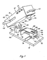
- the welding device shown in the figures comprises a base 10, a welding tool 12 provided with a chassis 14, an electric generator 16, control means 17 and a welding head 18 with Joule heating. , and a base 20 secured to the base 10 and intended to support a printed circuit 22 comprising conductive tracks 24 and an electrical component 26 provided with terminals 28 to be soldered to the circuit 22.
- the welding tool 12 is made integral with the base 10 by means of a joint 30 with a horizontal axis 32 by means of which it is pivotally mounted on this base.
- This articulation is composed of a vertical yoke 34 between the branches of which is mounted a plate 36 fixed to the chassis 14.
- a shaft 38 is engaged in these parts which it supports by means of bearings (not shown). The movement of the articulation towards the rear of the device is limited by a stop 40 which is integral with the yoke 34.
- a mass 44 is mounted in the chassis 14 so as to be able to move longitudinally therein.
- a rod 46 crosses the chassis longitudinally, passing through the mass 44.
- the latter is provided with a handle 48 which extends outside the chassis 14 so that the mass can be moved by hand. .
- the forward stroke of the device is limited by an adjustable stop 50 sliding on the rod 46 and which can be locked on the latter by a screw 52.
- the rearward stroke is limited by the rear wall of the chassis 14 or by a fixed stop not shown in the drawing.
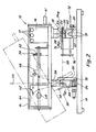
- the welding tool 12 When the mass 44 is in the latter position, it is desirable for the welding tool 12 to have a stable position both when it is inclined (fig. 1 and dashed line fig. 2), that is to say say in the clearing position of the working area, only horizontal (solid line in fig. 2), that is to say in the working position.
- the mass 44 When the mass 44 is moved forward, it generates a pressure of the welding head the greater the mass is advanced. As a result, the stop 50 ultimately determines this pressure with sufficient precision for the type of welding to be performed.
- the welding head 18 has two blades 54 and 56, mutually parallel and substantially perpendicular to the underside of the frame 14. These two blades 54 and 56 are coupled to the heat generator 16. More precisely but not shown in the figures, these blades are connected to the secondary of a transformer and thus heated by the Joule effect. Their lower edges 54a and 56a come into contact with the terminals 28 of the electrical component 26, in order to weld them to the conductive tracks 24. These edges define a plane 58, shown in phantom in Figure 2.
- the welding head 18 is positioned so that the plane 58 passes. by the axis 32.
- the base is dimensioned so that a plane defined by the upper surfaces of the terminals 28 also passes through the axis 32 and is thus coincident with the plane 58 during the welding operation. .
- This condition is not however specified thinkable; the head and the plate can thus be higher or lower, on the condition that the virtual cylinders centered on the axis 32 and respectively tangent to the plane 58 passing through the edges 54a and 56a of the blades and to the plane defined by the face upper bounds are confused.
- the base comprises a foot 60 secured to the base 10 and in the upper part of which is housed an inverted spherical cap 60a.
- the foot 60 carries a plate 62 intended to support the printed circuit 22.
- the plate 62 comprises in its lower part 62a a ring with a convex spherical lower surface resting in the cap 60a of the foot, to form with it a ball joint.
- a coil spring 64 hooked by one of its ends to a finger 66 which comprises the foot 60 and to the other to a loop 68 which comprises the plate 62, guarantees good stability of the latter.
- the base 60 further comprises holes 60c and 60d, in which rods 70, 72 are engaged, respectively carrying plates 74 and 76 vertical and orthogonal to each other and with the base 10, intended to position the printed circuit 22 in the horizontal plane (fig. 1 and 2).
- the apparatus further comprises a pneumatic damper 78 which cooperates with a lever 80 integral with the plate 36 of the articulation 30.
- the purpose of this damper 78 is to slow down the movement of the welding tool 12 when the head 18 s' approach the printed circuit 22 and the electrical component 26 in order to avoid damaging or moving the latter.
- the conductive tracks 24 are coated with flux, then the electrical component 26 is placed and positioned on the printed circuit 22, aligning the terminals 28 and the tracks 24.
- the welding operation proper can then begin. lowers the welding tool 12, by means of the handle 41. This movement takes place freely, until the lever 80 comes into contact with the brake piston 78. From this moment, the movement is slowed down, then stopped when the blades 54 and 56 come into contact with the terminals 28.
- the operator then moves the mass 44 by means of the handle 48, to increase the pressure of the blades 54 and 56, and starts the generator 16 by actuating the control means 17.
- this operation is advantageously carried out by heating the blades 54 and 56 to a temperature between 250 and 300 °, by applying a pressure of 1 to the terminals and the superimposed tracks. order 50 to 300 grams per lane, the welding operation lasting between one and five seconds.
- the example describes the assembly of an electrical component on a printed circuit. It is obvious that the terms electrical component and printed circuit are to be taken in a broad sense. Thus, the printed circuit can be replaced by any support comprising the conductive tracks. Furthermore, the electrical component could be an integrated circuit, but also a display cell, photoelectric cells, etc.
- the device described can be made more efficient by automating the welding tool, by electrical, hydraulic or pneumatic means, these means being able, moreover, to generate pressure during; of the welding operation.
- the welding head is only equipped with two blades. It is obvious that it can carry four more, as long as the component has terminals on its four sides.
- This device can also without further being transformed into a desoldering device, by associating at the end of the tool 12 next to the head 18 means for gripping the component, which make it possible to tear it from the printed circuit by removing the tool the head is still hot.
Landscapes
- Engineering & Computer Science (AREA)
- Mechanical Engineering (AREA)
- Electric Connection Of Electric Components To Printed Circuits (AREA)
- Manufacturing Of Electrical Connectors (AREA)
Claims (5)
Applications Claiming Priority (2)
| Application Number | Priority Date | Filing Date | Title |
|---|---|---|---|
| FR8419955 | 1984-12-26 | ||
| FR8419955A FR2575356B1 (fr) | 1984-12-26 | 1984-12-26 | Appareil de soudage pour assembler un composant electrique a un support |
Publications (2)
| Publication Number | Publication Date |
|---|---|
| EP0188796A1 EP0188796A1 (de) | 1986-07-30 |
| EP0188796B1 true EP0188796B1 (de) | 1988-10-19 |
Family
ID=9311052
Family Applications (1)
| Application Number | Title | Priority Date | Filing Date |
|---|---|---|---|
| EP19850116420 Expired EP0188796B1 (de) | 1984-12-26 | 1985-12-21 | Schweissapparat um einen elektrischen Bestandteil an einen Träger zusammenzusetzen |
Country Status (3)
| Country | Link |
|---|---|
| EP (1) | EP0188796B1 (de) |
| DE (1) | DE3565642D1 (de) |
| FR (1) | FR2575356B1 (de) |
Families Citing this family (2)
| Publication number | Priority date | Publication date | Assignee | Title |
|---|---|---|---|---|
| GB8720226D0 (en) * | 1987-08-27 | 1987-10-07 | Topping R J | Soldering apparatus |
| DE69803160T2 (de) * | 1997-02-17 | 2002-09-05 | Matsushita Electric Industrial Co., Ltd. | Verfahren und vorrichtung zur bestückung von elektronischen bauteilen |
Family Cites Families (3)
| Publication number | Priority date | Publication date | Assignee | Title |
|---|---|---|---|---|
| US3442432A (en) * | 1967-06-15 | 1969-05-06 | Western Electric Co | Bonding a beam-leaded device to a substrate |
| US3941292A (en) * | 1974-06-06 | 1976-03-02 | Anatoly Alexandrovich Osipov | Apparatus for soldering a plurality of flat conductors on a board |
| FR2307610A1 (fr) * | 1975-04-15 | 1976-11-12 | Matra Engins | Perfectionnements apportes aux appareils de soudage comprenant une electrode chauffante |
-
1984
- 1984-12-26 FR FR8419955A patent/FR2575356B1/fr not_active Expired
-
1985
- 1985-12-21 EP EP19850116420 patent/EP0188796B1/de not_active Expired
- 1985-12-21 DE DE8585116420T patent/DE3565642D1/de not_active Expired
Also Published As
| Publication number | Publication date |
|---|---|
| FR2575356A1 (fr) | 1986-06-27 |
| DE3565642D1 (en) | 1988-11-24 |
| EP0188796A1 (de) | 1986-07-30 |
| FR2575356B1 (fr) | 1988-05-13 |
Similar Documents
| Publication | Publication Date | Title |
|---|---|---|
| EP0132179B1 (de) | Operationstisch | |
| FR2779677A1 (fr) | Appareil manuel a couper les carreaux | |
| FR2644966A1 (fr) | Appareil destine a deraciner ou a dessoucher des plantes | |
| EP0188796B1 (de) | Schweissapparat um einen elektrischen Bestandteil an einen Träger zusammenzusetzen | |
| EP1147426A1 (de) | Messzange für stromleitern | |
| EP0104110B1 (de) | Kettenumsetzer für Fahrradantriebszahnkranz | |
| EP3694802B1 (de) | Greifvorrichtung für schalen | |
| FR2558567A1 (fr) | Dispositif de double commande mecanique d'un interrupteur, et machine en comportant application | |
| FR2548942A1 (fr) | Unite de soudage electrique par resistance du type ciseaux | |
| CH659607A5 (en) | Bonding apparatus for joining an electrical component to a support | |
| CA1304461C (fr) | Tete de trolleybus | |
| EP0704872B1 (de) | Mittelspannungsschalter oder Schutzschalter | |
| EP0097569A1 (de) | Anlage zur Herstellung von Bewehrungsgerippen für Stahlbeton | |
| EP0132176A1 (de) | Scherenförmiger Zangenapparat zum Zusammenbauen von Metallelementen mittels elektrischem Punktschweissen | |
| FR2516299A1 (fr) | Relais magnetique d'intensite temporise | |
| EP0002092B1 (de) | Gemüseschneidemaschine | |
| EP0281715B1 (de) | Elektrische Leiterabmantelungsmaschinen | |
| EP1145665A1 (de) | Klapptisch | |
| EP0176402A1 (de) | Schalter mit Selbstunterbrechung, insbesondere Differentialschalter und Schutzschalter | |
| FR2774977A1 (fr) | Appareil pour l'ouverture d'un recipient comportant un couvercle serti | |
| FR2784318A1 (fr) | Pince a souder permettant de modifier l'orientation de la baguette fusible lors de l'operation de soudage | |
| FR2685540A1 (fr) | Interrupteur-sectionneur d'exterieur perfectionne pour lignes moyenne et haute tensions. | |
| FR2759566A1 (fr) | Grille-pain electrique avec freinage du porte-pain au passage de la position de grillage a la position de prelevement | |
| FR3140587A1 (fr) | équipement portatif de griffage et de dégriffage d’une griffe d’un caténaire | |
| FR2715768A1 (fr) | Outil pour la manipulation des éléments de remplacement des dispositifs électriques de protection à fusibles. |
Legal Events
| Date | Code | Title | Description |
|---|---|---|---|
| PUAI | Public reference made under article 153(3) epc to a published international application that has entered the european phase |
Free format text: ORIGINAL CODE: 0009012 |
|
| AK | Designated contracting states |
Kind code of ref document: A1 Designated state(s): DE GB NL SE |
|
| 17P | Request for examination filed |
Effective date: 19860816 |
|
| 17Q | First examination report despatched |
Effective date: 19870504 |
|
| GRAA | (expected) grant |
Free format text: ORIGINAL CODE: 0009210 |
|
| AK | Designated contracting states |
Kind code of ref document: B1 Designated state(s): DE GB NL SE |
|
| PG25 | Lapsed in a contracting state [announced via postgrant information from national office to epo] |
Ref country code: SE Effective date: 19881019 Ref country code: NL Effective date: 19881019 |
|
| REF | Corresponds to: |
Ref document number: 3565642 Country of ref document: DE Date of ref document: 19881124 |
|
| GBT | Gb: translation of ep patent filed (gb section 77(6)(a)/1977) | ||
| NLV1 | Nl: lapsed or annulled due to failure to fulfill the requirements of art. 29p and 29m of the patents act | ||
| PLBE | No opposition filed within time limit |
Free format text: ORIGINAL CODE: 0009261 |
|
| STAA | Information on the status of an ep patent application or granted ep patent |
Free format text: STATUS: NO OPPOSITION FILED WITHIN TIME LIMIT |
|
| 26N | No opposition filed | ||
| PGFP | Annual fee paid to national office [announced via postgrant information from national office to epo] |
Ref country code: GB Payment date: 19921116 Year of fee payment: 8 |
|
| PGFP | Annual fee paid to national office [announced via postgrant information from national office to epo] |
Ref country code: DE Payment date: 19921219 Year of fee payment: 8 |
|
| PG25 | Lapsed in a contracting state [announced via postgrant information from national office to epo] |
Ref country code: GB Effective date: 19931221 |
|
| GBPC | Gb: european patent ceased through non-payment of renewal fee |
Effective date: 19931221 |
|
| PG25 | Lapsed in a contracting state [announced via postgrant information from national office to epo] |
Ref country code: DE Effective date: 19940901 |